
- •Introduction for English Version
- •Toshiaki Enomoto
- •Foreword
- •Table of Contents
- •Xj nsra, Japan
- •X;;; nsra, Japan
- •Chapter 5
- •Chapter 6
- •Chapter 1 General
- •History of Nuclear Power Plant Development
- •Experiences in Nuclear Power Generation and Safety Research
- •Comparison of Schemes of Nuclear and Thermal Power Generation
- •Effective Reactor Fuel Loading
- •Reactor Self-Regulation Characteristics
- •Reactor Decay Heat
- •Confinement of fPs
- •Reactor Steam Conditions
- •Safety Design Principles for npPs
- •Prevention of Occurrence of Abnormal Conditions (Level 1)
- •Figure 1.4.1 Defense-in-Depth philosophy
- •Prevention of Expansion of an Abnormal Event (Level 2)
- •Prevention of Abnormal Release of Radioactive Materials and Mitigation of Consequence (Level 3)
- •Emergency core cooling system
- •Confinement of radioactive materials by five barriers
- •Outline of Laws, Regulations and the Regulatory Framework
- •Domestic Framework
- •Permit to establish a power generating reactor
- •Sanction of the construction plan
- •Approval of technical specifications
- •Regulations after start of commercial operation
- •Iaea Safety Standards
- •Figure 1.5.4 Structure of iaea safety standards
- •Chapter 2 Systems of bwr Nuclear Power Plants
- •General Design Philosophy
- •Fuel Rods
- •Reactor Core
- •Reactor Coolant Pressure Boundary
- •Engineered Safety Features
- •Instrumentation and Control System
- •Other Systems
- •Plant Layout
- •Plot Plan
- •Grade level planning
- •Configuration of the buildings
- •Road planning
- •Pipe conduits and electric cable conduits planning
- •Construction area planning
- •Harbor and water intake/discharge planning
- •Other considerations
- •Main Buildings and Auxiliary Buildings
- •Figure 2.2.2 Overall plant layout of a bwr npp
- •Reactor building
- •Turbine building
- •Figure.2.2.7 Main building arrangements (two-unit site)
- •Main control room (Control building)
- •Radioactive waste treatment facility building
- •Service building
- •Exhaust stack
- •Advanced boiling water reactor (abwr) plant arrangement
- •Nuclear Reactor and Core
- •Fuel Rod and Fuel Assembly
- •Structure of fuel rod and fuel assembly
- •Figure 2.3.1 9x9 Fuel assembly (a type) and fuel rod structure (example)
- •Fuel rod and assembly designs
- •Reactor and Reactor Core
- •Structure of reactor and reactor core
- •Figure 2.3.4 Internal structure of a reactor pressure vessel (cut out view)
- •Vessel (rpv)
- •Incore monitor housing
- •Hpcf sparger top Fuel guide—
- •Reactivity control system
- •Core Design
- •Figure 2.3.20 Control rod with the maximum reactivity worth
- •Core stability
- •Operation and management of the core
- •Primary Coolant System
- •System Summary
- •Primary loop recirculation (plr) system
- •Main steam (ms) system
- •Feed water (fdw) system
- •Key Components
- •Reactor pressure vessel (rpv)
- •Figure 2.4.3 Control rod drive mechanism and in- core monitor housing
- •Recirculation pumps
- •Safety relief valve (srv)
- •Turbine System
- •System Summary
- •Main Turbine System and Auxiliary Equipment
- •Iypes of nuclear plant steam turbines
- •Steam turbine
- •Moisture separator and heater
- •Electro-hydraulic turbine control (ehc) unit
- •Main Steam System and Condensate Feed Water System
- •Main steam line and turbine bypass system
- •Steam extraction system and feed water heater drain system
- •Condenser and circulating water system
- •Condensate and feed water system and condensate cleanup system
- •Instrumentation and Control System
- •Reactor Instrumentation and Control System
- •Plant control system
- •Reactor neutron monitoring system (nms)
- •0 Source range monitor (srm) 4 detectors q Power range monitor (prm) 43x4detectors
- •Main Control Room
- •Structure and functions of control panels
- •3BbBia3b3jjsbj5ca;nS1ss!aacBa3caoanoDaj3j;|
- •Remote shutdown system (rss)
- •Emergency operational facilities
- •Process Instrumentation System
- •Reactor process instrumentation system
- •Figure 2.6.14 Reactor water level and pressure instrumentation
- •Radiation monitoring system
- •2.7 Engineered Safety Features
- •Design Policy of Engineered Safety Features
- •Basic safely philosophy
- •Philosophy to prevent occurrence of serious incidents
- •Philosophy to mitigate serious incidents
- •Emergency Core Cooling System (eccs)
- •Roles of the eccs
- •Criteria for design and evaluation of eccs
- •Design policies for the eccs
- •Eccs configuration
- •Eccs configuration of an abwr
- •Reactor Containment Facility
- •Roles of reactor containment facility
- •Primary containment vessel (pcv)
- •Containment spray system (css)
- •Flammable gas control system (fcs)
- •Standby gas treatment system (sgts)
- •Reactor containment facility of an abwr
- •Reactor Auxiliary Systems
- •Residual Heat Removal (rhr) System
- •Operating modes
- •System functions and configuration
- •Reactor Core Isolation Cooling (rcic) System
- •System functions and configuration
- •Reactor Water Cleanup (cuw) System
- •System functions and configuration
- •Key components and features
- •Fuel Pool Cooling and Cleanup (fpc) System
- •System functions and configuration
- •Figure 2.8.8 cuw pump (canned motor type)
- •Reactor Building Cooling Water (rcw) System and Reactor Building Cooling Seawater (rcws) System
- •System functions and configurations
- •Key components and features
- •Figure 2.8.10 Basic concept of rcw and rcws systems (example)
- •Fuel Handling and Storage System
- •Spent fuel storage pool
- •Cask pit
- •Refueling machine
- •Radioactive Waste Treatment Systems
- •Gaseous Waste Treatment System
- •Figure 2.9.1 a typical flow sheet of gaseous wastes treatment system (Example of a 1,100 mWe bwr plant)
- •Liquid Waste Treatment System
- •Solid Waste Treatment System
- •Generator excitation system
- •Major Transformers and Switchyard System
- •Major transformers
- •Switchyard system
- •Plant Auxiliary Power System
- •Plant auxiliary power supply system
- •Emergency diesel generator system
- •Direct current (dc) power supply system
- •Instrumentation and control power supply system
- •Plant Auxiliary Systems
- •Plant Water System
- •Plant water treatment system
- •Make-up water system
- •Auxiliary Steam System (House Boiler System)
- •Design philosophy
- •Key equipment
- •Compressed Air Supply System
- •Design philosophy
- •Key equipment
- •Heating, Ventilating and Air Conditioning (hvac) System
- •Design philosophy
- •Key equipment
- •Figure 2.11.6 Outline of hvac system of the turbine building
- •Figure 2.11.7 Outline of hvac system of the main control room
- •Fire Protection System
- •Key equipment
- •Advanced bwr (abwr)
- •Design Principles
- •Enhanced safety and reliability
- •Figure 2.12.2 Reactor buildings (a 1,100 mWe bwr and an abwr)
- •System design
- •Advanced core
- •Reactor system
- •Reinforced concrete containment vessel (rccv)
- •Turbine system
- •Enhanced Safety
- •Improved reactor shutdown capabilities
- •I turbine driven reactor feedwater pump||
- •Figure 2.12.8 abwr safety features
- •Enhanced reactor cooling capability
- •Enhanced capability for containing radioactive materials
- •Overall safety
- •Figure 2.12.10 abwr eccs (three divisions)
- •Enhanced Operability and Maneuverability
- •Improved monitoring and maneuverability
- •Enhanced operability
- •Chapter 3 Systems of pwr Nuclear Power Plants
- •General Design Philosophy
- •Fuel Rods
- •Reactor Core
- •Engineered Safeguard Systems
- •Instrumentation and Control System
- •Other Systems
- •Plant Layout
- •Plot Plan
- •Intake and discharge structures
- •Switchyard
- •Reactor building and reactor auxiliary building
- •Turbine building
- •Water supply and treatment system
- •Radioactive waste storage building
- •Cask storage building
- •Harbor facilities
- •Access control system
- •Equipment Arrangement
- •Reactor building
- •Reactor auxiliary building
- •Turbine building
- •Fuel handling and storage building and facilities
- •Plant Layout Considerations
- •Building composition
- •General requirements of plant layout design
- •Decontamination Pi t
- •Isolation Valve
- •2 Loop Plant
- •3 Loop Plant
- •Figure 3.2.7 Buildings configurationn of nuclear power plants in japan
- •Figure 3.3.1 Schematic of fuel assembly and fuel rod
- •Structure of the fuel rods and fuel assemblies
- •Design of fuel rods and fuel assemblies
- •Figure 3.3.2(2) Support grid structure (2)
- •Reactor and Reactor Core
- •Structure of reactor and reactor core
- •Dynamic characteristics of the nuclear reactor
- •Core stability
- •Reactivity control
- •Figure 3.3.13 Critical boron concentration vs. Burnup (hot full power (hfp), all rods out)
- •Power distribution control
- •Figure 3.3.15 Reactivity worth of control group bank d (beginning of cycle, hot zero power, no xenon; example 4-loop core)
- •Figure 3.3.16 Structure of primary neutron source assembly
- •Figure 3.3.17 Structure of secondary neutron source assembly
- •Core management
- •Reactor Coolant System
- •Outline
- •System summary
- •System functions
- •Main Components
- •Reactor vessel
- •Steam generators
- •Pressurizer
- •Vertical u-lube type heat exchanger 7.D8 mPa [gage]
- •17.16 MPa (gage]
- •Reactor coolant piping
- •Reactor coolant pumps
- •IVol. Seal
- •Turbine System
- •Outline
- •Main Turbine and Its Appurtenances
- •Characteristics of Nuclear Power Plant Turbines
- •Turbine types, blade designs and steam cycles
- •Structures of turbines
- •Table 3.5.2 Turbine type and applicable output
- •Turbine governor system
- •Turbine steam inlet valves
- •Turbine protection system
- •Main Steam System
- •Main steam safety and relief valves
- •Main steam isolation and check valves
- •Turbine bypass valves
- •Condensate, Feedwater System and Other Related Systems
- •Condensate, feedwater system
- •Auxiliary feedwater system
- •Circulating water system
- •Instrumentation and Control System
- •Reactor Instrumentation and Control System
- •10 5 Neutron Source Range Trip Point
- •Figure 3.6.1 Out-of-core nuclear instrumentation range of measurement
- •High Neutron Flux {Power Range High Selling)
- •Sleam Generator Feedaler Flow Level tl *
- •Interlock
- •Reactor
- •Turbine Load Neutron Flux Level
- •Injection Pump Actuation
- •2/4 Logic
- •Figure 3.6.6 Pressurizer pressure protection and control system
- •Reactor control system
- •Figure 3.6.11 Feedwater control system
- •Main Control Room
- •Composition of main control board
- •Methods for monitoring and operation
- •Alarm system
- •(1) Vdu monitor operation example of the screen (system screen)
- •(2) Vdu monitor operation example of the screen (control screen)
- •(3) Vdu monitor operation example of the screen (screen monitors only)
- •Operator assisting system
- •Plant operation management
- •Reactor shutdown panel outside the main control room
- •Emergency support plan
- •Process Instrumentation System
- •Primary system
- •Secondary system
- •Radiation Monitoring System
- •Process radiation monitors
- •Area monitors
- •Radiation measurement during accidents
- •Engineered Safety Feature
- •Systems and Their Functions
- •Emergency core cooling system (eccs)
- •Reactor containment facility
- •Containment spray system
- •Annulus air clean-up system
- •Safety component room air clean-up system
- •General points
- •Emergency Core Cooling System (eccs)
- •Functions
- •System configuration
- •Reactor Containment Facility
- •Functions and configuration
- •Functions and structure of the different containment vessels
- •External shield building
- •Annulus
- •Containment Spray System
- •Function
- •System configuration
- •Iodine removal chemicals tank
- •Functions
- •Components
- •Safety Component Area Air Clean-up System
- •Functions
- •Components
- •Reactor Auxiliary Systems
- •Chemical and Volume Control System (cvcs)
- •System composition and functions
- •Inside coo tai oment
- •Injection pump —:—
- •Components
- •Residual Heat Removal System (rhrs)
- •System composition and functions
- •Component cooling water |m1
- •Components
- •Component Cooling Water System (ccws)
- •System composition and functions
- •Components
- •Instrument air compressor a
- •Instrument air cos pressor b
- •I .Aurillary components,
- •I [important for safetyj
- •Sea Water System (sws)
- •Spent Fuel Pit Cooling and Clean-up
- •Fuel Handling System
- •Radioactive Waste Disposal System
- •Gaseous Waste Disposal System
- •Liquid Waste Disposal System
- •Figure 3.9.4 Boron recycle system evaporator (immersion heater type)
- •Solid Waste Disposal System
- •Electrical Systems
- •Main Generators and Appurtenances
- •Appurtenances of the main generators
- •Generator excitation system
- •Voltage regulator
- •Major Transformers and Transmission System
- •Generator load break switch (glbs)
- •Switchyard
- •Plant Auxiliary Power Supply
- •Figure 3.10.4 Switchyard bus composition
- •311 Power transformer
- •Dc power supply systems
- •Instrument power systems
- •Figure 3.10.6 Direct current power supply system (one of safety system)
- •Board feu | 4 c Icard for j I c
- •(Note)Wllh mechanical Interlock
- •Compressed Air Systems
- •Drain line
- •Sieaj control valve for turbine
- •Inside containment
- •Heating, Ventilating and Air Conditioning Systems
- •Figure 3.11.5 Auxiliary building heating, ventilating and air-conditioning system diagram (general & safety component rooms)
- •Figure 3.11.6 Auxiliary building heating, ventilating and air-conditioning system diagram (main control room)
- •Fire Protection System
- •Figure 3.12.1 Schematic view of apwr steam generators
- •Enhancement of reliability
- •Improvement of operability
- •Reduction of radiation exposure
- •Plant Design
- •Core internals
- •Steam generator
- •Instrument and control system
- •Turbine generator
- •Conclusion
- •Chapter 4 Operation and Maintenance of bwr Plants
- •Plant Operation
- •Plant Startup
- •Figure 4.1.1 Schematic diagram of bwr plant system
- •Figure 4.1.2 Startup curve after periodic inspection
- •Figure 4.1.3 Operating range of core thermal power and core flow
- •Normal Plant Operation
- •Implementing surveillance tests
- •Core management during operation
- •Chemistry control during plant operation
- •Other operational activities
- •Plant Shutdown
- •Chemistry control during plant shutdown
- •Plant Maintenance
- •Figure 4.2.1 Administrative classification of maintenance
- •Periodic Inspections and Licensee’s Periodic Inspections
- •Periodic inspections
- •Licensee’s periodic inspections
- •Time to carry out licensee’s periodic inspections (including the periodic inspections) and periodic checks
- •Items for the periodic inspections and licensee’s periodic inspections
- •Procedure and Work Schedule of Periodic Inspections
- •VII) Preparations for startup
- •IV) Fuel exchange & shuffling
- •VI) pcv upper head Qf ’
- •Other major work activities
- •Figure 4.2.4 Reactor recirculation pump
- •Contents of isIs
- •Remote automatic ultrasonic testing device for isIs
- •Checks and Maintenance during Plant Operation
- •Switching components during operation
- •Maintenance during operation
- •Efficiency Improvement of Periodic Inspection Work
- •Improvement of plant layout
- •Reduction of the time needed for the periodic inspection
- •Maintenance Against Plant Aging
- •Technical Study on Aging
- •Upgrading of evaluation technology
- •Maintenance Technology against Aging
- •Figure 4.3.3 Concept of seal weld
- •Figure 4.3.5 Core shroud tie rod
- •Figure 4.3.8 Principle of crc
- •Figure 4.3.11 Conceptual diagram of wol pipe cross section
- •Upgrading by Facility Replacement
- •Chapter 5 Operation and Maintenance of pwr Plants
- •Plant Operation
- •Reactor Control Systems
- •Control rod control system
- •Turbine bypass control system
- •Pressurizer pressure control system
- •Pressurizer water level control system
- •Steam generator water level control system
- •Plant Startup
- •Plant Normal Operation
- •Operator Activities during Plant Normal Operation
- •Plant Shutdown
- •Chemistry Control
- •Outline of chemistry control of primary system
- •Outline of chemistry control of secondary system
- •Management of waler trealment chemicals
- •Sg blow down water recovery system
- •Plant Maintenance
- •Maintenance Management Policy
- •Periodical Inspections and Periodical Utility Inspections
- •Figure 5.2.2 Framework of plant in-service inspection system
- •Major activities in the periodical inspection period
- •0Utline of other major activities
- •Table 5.2.2 Overhaul inspection required by regulations
- •Maintenance during plant normal operation
- •Checks during plant normal operation
- •Maintenance dining plant normal operation
- •Rationalization of Plant Features Related to Periodical Inspections
- •Optimization of plant equipment arrangement
- •Reduction of durations for periodical inspections
- •Reduction of radiation dose
- •Maintenance to Cope with Plant Aging
- •Technical Evaluation of Aging Effects
- •Maintenance Techniques to Cope with Plant Aging
- •Maintenance of Alloy 600
- •Upgrading of Plants by the Renewal of Systems
- •Chapter 6 Radiation Control
- •Purposes of Radiation Protection
- •Regulation for Radiation Protection
- •Legislative System for Radiation Protection
- •Specific Applications of Legislation
- •Industrial Safety and Health Law
- •Radiation Sources at npPs
- •Actual Conditions concerning Radiation Sources
- •Figure 6.3.1 (1) Trends in dose equivalent rates of the bwr plr system piping
- •Area Control
- •Standards of Area Control in Accordance with Legislation
- •Confirmation of Radiation Environment
- •Access to and Exit from Controlled Areas
- •Work Management
- •Study of Work Methods
- •Approval of Radiation Work
- •Confirmation of Work Environment
- •Completion of Work
- •Fundamentals of Radiation Protection for Work Management
- •6.7 Controls of the Individual
- •Qualification of Radiation Workers
- •Evaluation of Individual Dose
- •Target of Individual Dose Control
- •Records of Individual Dose
- •Track Record of Individual Dose
- •Figure 6.7.1 History of the number of npPs, number of radiation workers, and total dose in Japan (excluding gcr)
- •Fiscal year Figure 6.7.5 Trends in annual average total doses per npp in major counties
- •Radioactive Waste Management
- •Radioactive Solid Wastes
- •Radioactive liquid Wastes
- •Figure 6.8.3 Trends in total amount of solid wastes stored as of the end of each fiscal year (for each type of light water reactor) and the number of drums sent to the Rokkasho Center
- •Tire level to classify the "materials not required to heat as radioactive materials" as the radioactivity is low enough
- •Figure 6.8.5 Outline of the clearance system
- •Fiscal year
- •Figure 6.8.6 Trends in discharged radioactivity of radioactive liquid wastes (excluding tritium) (total discharge for each reactor type)
- •Fiscal year
- •Environmental Radiation Monitoring
- •Chapter 7 Safety Evaluation of
- •Bwr Plants
- •Basic Policy for Safety Evaluation
- •Objectives of Safety Evaluation
- •Anticipated Operational Occurrences
- •Assumption of Event
- •Abnormal Withdrawal of Control Rods during Reactor Startup
- •Loss of Feed Water Heater
- •Loss of Load
- •Features of abwr Transient Analysis
- •Accidents
- •Assumption of Events
- •Loss of Reactor Coolant (in case of a Large Break)
- •Time after the accident (s)
- •Characteristics of abwr Accident Analysis
- •Major Accidents and Hypothetical Accidents
- •Assumption of Events
- •Loss of Reactor Coolant
- •Main Steam Line Break
- •(Note) These numbers are to be used for the whole body dose evaluation together with those of noble gases.
- •Figure 7.4.2(1) Process of iodine release during the main steam line break (major accident)
- •Dose Evaluation
- •(Note) These numbers are to be used for the whole body dose evaluation together with those of noble gases.
- •Probabilistic Safety Assessment (psa) for bwRs
- •Psa during Operation
- •Figure 7.5.1 Contribution of each sequence to the core damage frequency
- •Psa during Shutdown
- •Severe Accident
- •Chapter 8 Safety Evaluation of
- •Pwr Plants
- •Basic Principles for Safety Evaluation
- •Purposes of Safety Evaluation
- •Methodology for Safety Evaluation
- •Abnormal Transients during Operation
- •Postulation of Events
- •Partial Loss of Reactor Coolant Flow
- •Figure 8.2.1 Partial loss of reactor coolant flow (• indicates the initial value)
- •Uncontrolled Control Rod Withdrawal at Reactor Startup
- •Loss of Normal Feedwater Flow
- •Figure 8.2.2 Uncontrolled control rod withdrawal at reactor startup (•Indicates the initial value)
- •Accidents
- •Postulation of Events
- •Loss of Reactor Coolant
- •Steam Generator Tube Rupture
- •Major Accidents and Hypothetical Accidents
- •Postulation of Events
- •Loss of Reactor Coolant
- •Steam Generator Tube Rupture
- •Release from fuel rods to the reactor system
- •Release from the primary system to the secondary system
- •Release into the atmosphere
- •Probabilistic Safety Assessment (psa) for pwr Plants
- •Outline of Probabilistic Safety Assessment
- •Use of psa for safety management in the shutdown state
- •Chapter 9 Siting
- •Site Assessment
- •Site Conditions
- •Procedures for Site Assessment
- •Environmental impact assessment
- •Preliminary public hearing
- •Designation of important electric power development area
- •Basic Philosophy of Site Safety
- •Site Review Procedures and Contents
- •Hie Concept of Site Safety in the iaea Site Safety Standard
- •Reactor Site Criteria in the u.S.
- •Siting Philosophy
- •Site Assessment
- •Procedure for Radiation Effect Evaluation
- •Nuclear Emergency Preparedness
- •Seismic Safety
- •Basic Policy on Seismic Design
- •Figure 9.5.1 Formulation flow chart of design basis earthquake ground motion Ss ote£g)
- •Elastically design earthquake ground motion Sd (edegmSd)
- •Seismic Assessment
- •In the equipments
- •Seismic assessment of equipment and piping system
- •Maritime Environment Protection
- •The Effects of Thermal Effluent
- •Hie Effects of Coastal Structures
- •Advanced Siting Concept
- •General
- •Need for qa Activities in Nuclear Power Plants (npPs)
- •Addressing qa
- •International Trends in qa Activities for npPs
- •Development of Commercial qa Standards in Japan
- •1996 (Country taking part in un)
- •Establishment of jeac4111-2003
- •Quality Management System (qms)
- •Figure 10.2.2 Process diagram on npp (example)
- •Stipulation of qms
- •Provision of quality policy and quality objectives
- •Presentation of evidence of effective operation of qms
- •Document Control
- •Record Control
- •Management Responsibility (Top Management)
- •Quality Policy and Quality Objectives
- •Management Representative
- •Review by Management (Management Review)
- •Table 10.3.2 Three outputs on management review
- •Education and Training (Human Resources)
- •Product Realization Planning (Work Planning)
- •Noncon forming action/corrective action
- •Preventive action
- •Relationship with Customer
- •Determination and Review of Requirements related to the Product (Work)
- •Customer Communication and Customer Satisfaction
- •10.6 Design and Development
- •Planning of Design and Development
- •Verification
- •Validation
- •Figure*! 0.6.1 Process flow of design and development
- •Inputs to Design and Development
- •Outputs from Design and Development
- •Review of Design and Development
- •Table 10.6.2 Examples of verification items in the design review
- •Verification of Design and Development
- •Validation of Design and Development
- •Configuration Management of Design and Development
- •Purchasing
- •Purchasing Process
- •Communication with Suppliers
- •Purchasing Requirements
- •Verification of Purchased Products
- •Table10.7.1 Examples of purchase requirements
- •10.8 Production and Service Provision (Implementation of Work)
- •Control of Production and Service Provision (Control of Work)
- •Validation of Processes
- •Analysis of data and improvement (Sec.10.10)
- •Analysis of data
- •Nonconforming action / corrective action
- •Preventive action
- •Table 10.8.1 Controlled conditions and their examples
- •Identification and Traceability
- •Control of Monitoring and Measuring Devices
- •Monitoring & Measurement and Internal Audit
- •Product realization(Sec.L0.5) Production and service provision (implementation of work) (Sec. 10.8)
- •Monitoring and Measurement of Processes
- •Table 10.9.5 Examples of the monitored and measured items for npPs
- •Internal Audit
- •Analysis of Data and Improvement
- •Analysis of Data
- •Nonconforming Control & Corrective Action
- •Product realization(Sec.L0.5) Production and service provision (implementation of work) (Sec. 10.8)
- •Figure 10.10.1 pdca cycle for product realization in the quality management system
- •Preventive Action
- •Appendixes
- •Appendix 1 Chronology of Nuclear Power Plants
- •Improved transient performance
- •Improvement of plant availability
- •Improved main control board (1990s)
- •Appendix 8 The Outline of International Nuclear Event Scale (ines)
* Once per every 3 periodic
inspection periods
Figure
5.2.4 Standard schedule for periodic Inspection
Major activities in the periodical inspection period are opening and
checking the reactor vessel, checking the soundness of fuel and
making replacements, inspecting SG tubes, opening and checking the
turbine, verifying the integrities of components and materials
(in-service inspections), and carrying out leak rate tests of the
containment vessels, operability tests of safety protection
circuits, and plant performance tests.
The sequence of major check and inspection activities of the primary
systems in a typical periodical inspection period of a typical PWR
plant is described below when no plant modification is implemented.
i ) Opening of reactor
The sequence to shut down an operating plant starts with the
disconnection of the main generator from the grid, continues to the
reduction of the temperature and the pressure of the reactor coolant
system followed by subsequent degassing and oxidizing operations of
the reactor
coolant After the reactor coolant.system
is cooled down, and the containment air is purged by the ventilation
system, the air lock of the containment is opened and operations in
the containment are begun. After the missile shielding structures
are removed, interconnected systems and devices such as seismic
supports, electrical cables of the control rod drive mechanism and
cooling fan connecting ducts are disconnected. Secondly, in- core
thermocouple housings in contact with the reactor coolant are
disassembled and stud bolts of the reactor vessel are loosened and
removed. In parallel with the above activities, thimbles for in-core
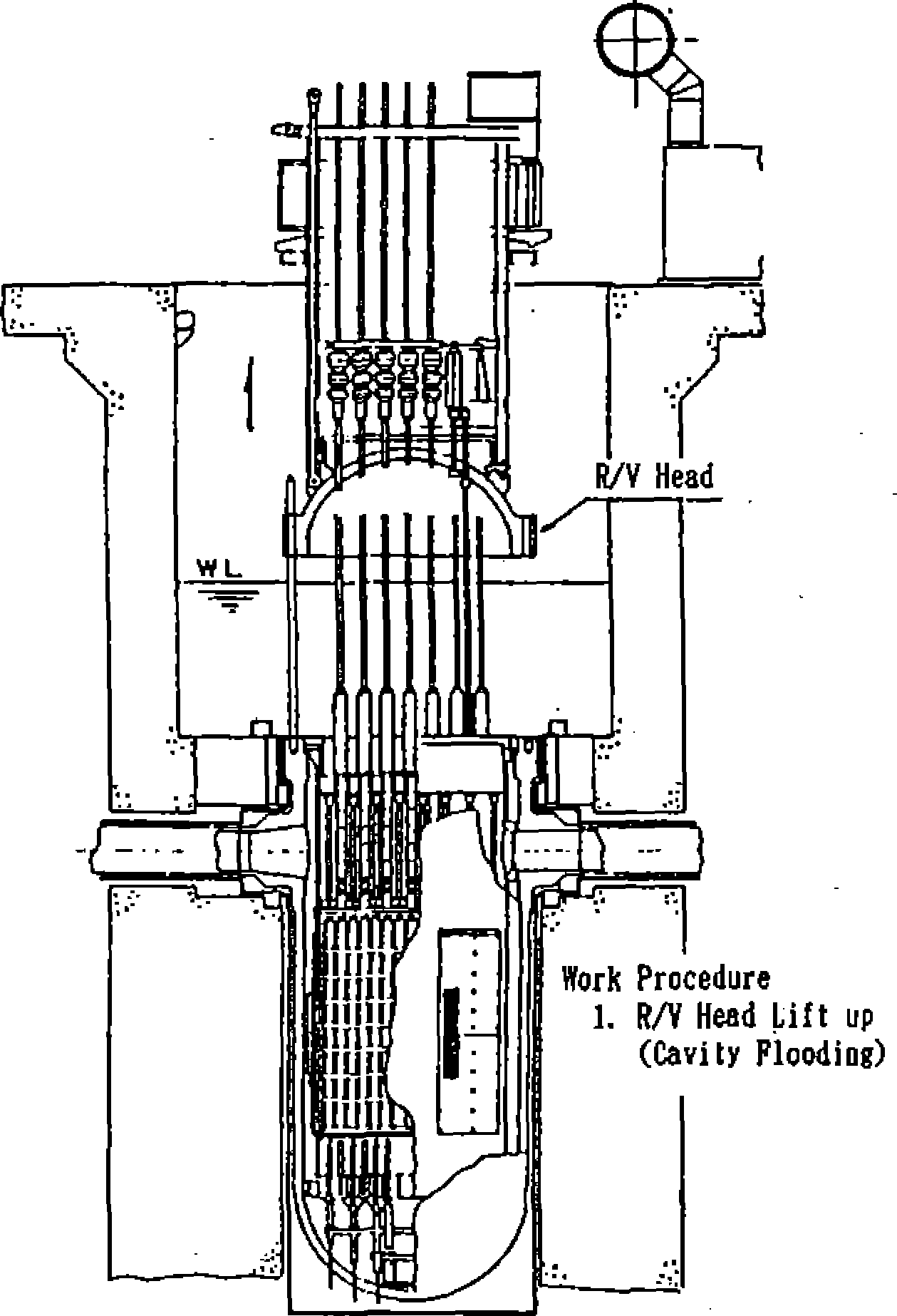
instrumentations are withdrawn. Subsequently, the reactor cavity is
filled with water. The reactor vessel head is lifted, keeping pace
with the increasing water level, and moved to a temporary lay-down
space on the operating floor. When the reactor cavity is completely
filled with water, control rod drive shafts are unlatched from the
control rods and removed. The
upper core internal assembly is lifted, but kept under water, and
moved to a temporary lay-down
NSRA,
Japan
5-
18Major activities in the periodical inspection period
Chapter
5 Operation and Maintenance of PWR Plants
location on the cavity floor.
The steps of the reactor opening are illustrated in Figure 5.2.5.
ii) Transfer and
inspections of fuel
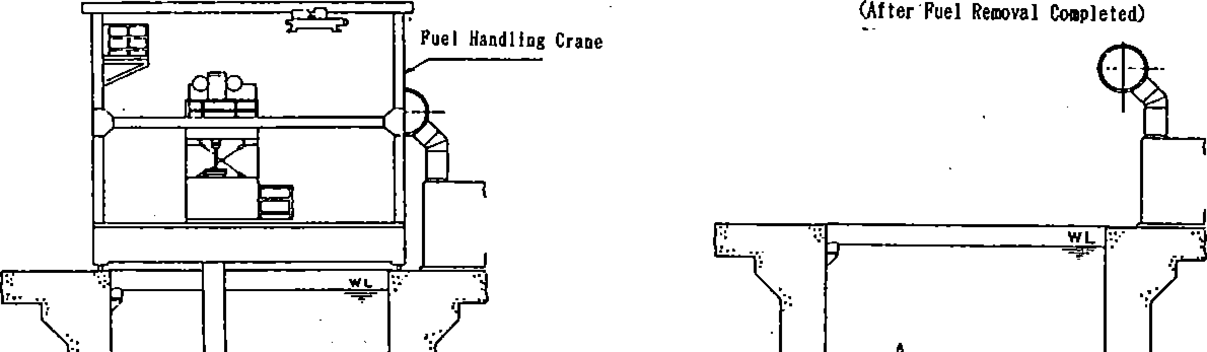
After the activities to open the reactor are completed, fuel
assemblies in the reactor vessel are transferred to the spent fuel
pit outside the containment using a fuel handling crane and a fuel
transfer system. Spent fuel assemblies which are transferred to the
pit are visually checked with an inspection unit installed in the
pit (underwater TV inspection). Sipping inspections of fuel are also
conducted, if necessary, to confirm the soundness. Burn-ups of spent
fuel assemblies for which soundness has been confirmed by the
inspections and are to be reloaded in the reactor are calculated,
and the optimum loading pattern of these reused fuel assemblies
mixed with new fue assemblies is established by pattern calculations
to determine locations for the reused fuel assemblies. Based on the
core loading pattern, items inserted into fuel assemblies are
reshuffled and the fuel assemblies are loaded into the reactor core
in the reverse order to the procedures for removing them. Fuel
assemblies and items inserted into assemblies are visually confirmed
to be in their proper locations with an underwater TV observation.
iii) Eddy current test of steam generator tubes
The number of heat transfer tubes of a SG is more than 3,000. For
SGs with heat transfer tubes of nickel based Alloy 600 (Inconel
®600), inspections are
made during every periodical inspection using the non-destr
uctive eddy current test (ECT) method throughout the entire
lengths of the tubes. For SGs with nickel based Alloy 690 (Inconel
®690) tubes, inspections are made only every two inspection
periods. Reactor coolant in SG tubes needs to be drained out before
the ECTs. When the water level in the reactor cavity is decreased
once in the process of reactor opening, and the water in the SG
tubes has drained out, the covers of manholes on the water chambers
of SGs are opened and nozzles connecting the water chambers to the
reactor coolant piping are closed with plugs to isolate the water
chambers from the reactor coolant system. The nozzle plug design is
a feature invented to rationalize
periodical inspections. Before this plug design was adopted, ECTs of
SGs were interrupted every
time when the reactor cavity water level was raised for the fuel
removal or loading, and that resulted in long times and much effort
for ECTs. The ECT equipment consists of two or four flaw testing
coils (probes), and they are positioned at the inlets of the tubes
by a robot in the first step and in the second step they are
inserted into the tubes by a pusher. The
robot and the pusher are remotely and/or automatically operated from
an operating unit in a container house set outside of the
containment. The soundness of the heat transfer tubes is verified
based on the analysis of eddy current changes detected by the probes
which move at high speeds in the tubes along their full length. A
typical SG tube ECT system is illustrated in Figure 5.2.6.
Reassembling of reactor vessels, water pressure testing of reactor
coolant system and leakage rate testing of containment
After it is made certain all fuel is being properly loaded in the
reactor core, the reactor vessel and its attachments are reassembled
in the reverse order of its opening procedures. In- core
thermocouple housings and vessel stud bolts are fastened and a leak
test of the reactor coolant system is performed. The testing efforts
are focused on the parts which were opened or disassembled for the
refueling operations and the periodical inspections. After that all
penetrations and the air lock of the containment are closed and
leakage rate of the containment is tested. The containment pressure
is raised to a specified value for this and it is maintained at this
pressure for a specified period to check that the leakage rate is
below a specified rate. Instead of such an overall leakage testing,
called Class A testing, the leakage rate of the containment may be
checked with a local leakage rate testing method (Class B and Class
C tests).
Preparations for reactor startup
The leakage rate testing of the containment is the final step of the
refueling operations and the checking of the plant equipment, and it
is followed by activities for starting up the plant. The
configurations of all systems are aligned for the plant startup.
Performance tests of system
5-
19
NSRA,
Japan
Procedure
(D
CRDU
Cooling Duct
*
Electric Circuit (Cable Bridge)
Procedure
@
Missile
Shield
Cavity
Seal Ring
Force Down Plate
mu
inn
urn
HUI
mi
mi
HUI
T/C
Cable
Work
Procedure
Work
Preparation Polar Crane Check up
Tool
Check up and Preparation
Missile
Shield Reaova!
CRDM
Cooling
Duct Renova
I
Electric
Circuit Disconnection
Cavity
Sea! Ring Force Down Plate Reaoval
Procedure©
Procedure
@
Seismic
Support Rod
Work
6.
2.
3.
4.
5.
Guide
Stud Inslatlon
Cavity
Seal Ring
ffftT
nni
HUI
mu
IIIII
nn
ini
IlJll
Protector
Stud
Hole Plug
Procedure
T/C
Protector Installation Stud Hole Plug installation Guide
Stud Installation Seismic
Support Rod Removal Cavity
Seal Ring Installation Leak Test
R/V
Head Lift up Preparation
Figure
5.2.5 The steps of the reactor opening (1/2)
NSRA,
Japan
5-20
Chapter
5 Operation and Maintenance of PWR Plants
Procedure
®
Procedure
®
Procedure®
.R/V
Seal Plate
Figure
5.2.5 The steps of the reactor opening (2/2)
5-21
NSRA,
Japan
functions and inter-system functional tests are conducted to ensure
that the plant is safely operated and can be shut down when
necessary. The reactor plant is started after the functional testing
and its load is increased to the rated value,
before final testing at the full load. When the full load test is
completed and the plant is verified to be operated steadily under
its full load, the periodical inspection of the plant is completed.
Inside
reactor containment
E CT probe
Robot (MR-lll)
TV camera
Inside loop
compartment
Heat transfer
tubes
Water
chamber
Interface unit (No.land No.2)
Headphone
Monitoring/ communication
relay box
Fiber optic transmission unit
Robot relay box
(doubling as air supply panel)
Pusher relay box
(doubling as air supply panel)
Pusher
(EWS)
Pusher power supply
Fiber optic cable
Monitoring/comm
unication unit
Flaw testing computer
Main computer
Cabinet
Power supply(440V)
Fiber optic transmission unit
Container house
Interface unit
Outside reactor containment
Figure
5.2.6 Example of SG Tube ECT Unit
NSRA,
Japan
5-22
Chapter
5 Operation and Maintenance of PWR Plants
In-service inspections
Non destructive inspections of the following equipment are required
by law.
■ Class 1 components composing the reactor coolant pressure
boundary including the reactor vessel
Class C component—reactor
containment vessel
Class 2 components consisting of vessels, pumps, piping and valves
of engineered safeguard systems and emergency reactor shutdown
systems
Class 3 components consisting of vessels, pumps, piping and valves
of indirect supporting systems for the safety important systems
Support structures for safety important equipment
Core internals
Inspections of the above components are systematically planned and
executed in the periods of periodical inspections of a plant to
complete the inspections of necessary components in a 10-year
cycle. The inspections are conducted as part of periodical utility
inspections. Details of items and methods of inspections are defined
in the JSME S NAI-2002 “Maintenance Rules” published by the
Japan Society of Mechanical Engineers.
Inspections described in the rules include surface checks such as
visual checks and liquid penetrant tests (PT), non-destructive tests
including volumetric tests represented by ultrasonic tests and
system leakage tests. ECTs applied to SG tubes are referred to in
the rules as a sort of volumetric test for in-service inspection.
Lower core internals in a reactor vessel are removed at least once
every 10 years, to allow close inspection of welds in the reactor
vessel. The reactor vessel is inspected from inside using ultrasonic
flaw testing equipment; an A-UT machine is shown in Figure 5.2.7.
Remote operation of the equipment and recording and evaluation of
flaw data are all centralized to control panels and data processing
units in container houses temporarily
Figure
5.2.7 Example of R/V ultrasonic testing unit
5-23
NSRA,
Japan