

fuel
assembly
Taking
generator off the
7
i) Reactor opening
grid
works
I
Synchronization
V
vili)
Integrated load test
Critical
path
(reactor works)
Removal
of [
PCV
&
RPV )
upper
heads
•Removal
of dryer &
separator
Installation
of main steam
line plug
Irradiated
insnection
fl
icl
pool sidel
&
i
i) Fuel Q
transfer
1
tO
LPRM,<
CR
L
iii)
Remo /al,
overhaul
inspcctioi
s & installation of 1
crd
r '
v)Reacto:
restoration works
RPV
uppertend
installatioC
Core
checkf.
Dryer
separ
tor
installation
O')’
Draining &
[
reactor well
!■
RPV
upper
lead
installation
Control
drive system (CRD)
Main
steam isolation valve (MSIV)
From
line plug installation
j.
MSIV
A,
leak
test
]
[
Removal
r i
installatii
i
',0
overhaul
inspections &
n of CRD i
o
MSIV
leak test (
(removal of line
plug)
i
CRD func
ional
test
]
Air vent, c
rive test,
i
scram test
Insp
:ction
of MSIV
installation
& \
leak
test i
d
RPV
hydrostatic test
System
tests Integrated functional test Integrated functional test
Fla
it startup
Main
steam
safety/relief valve (MS
S«V)
In-service
inspection
Q— (ISI)
Reactor
water
clean-up system
(CUW)
Reactor recirculation
system
(PLR)
Main
turbine
Q-
5
o
^Inspection
&.
fu ictional
test of Mi
S/RV
i
Ih-service
inspection
Inspection
of CUV7
pump (one train alway;
in service)
o':
Inspection
of reactor
:
recirculation pump mecl anical
seal
Disassembl
y
of main turbine
Opening
of HP ar 1LP
stage casings
XD
Lubricating
oil syste n. flashing
-
-
■
Inspection
of
main turbine
rOOv
‘O
0/
Disassembly
of major
valves
Main
turbine valves Q
Main
steam
stop
t
alve
Steam
control val
Combined
interne jt
valve
Turbine
bypass v;
Ive
o
o
Rotor,
blade, nozde,
I
caring,
shaft
coupling, labyrii
th packing,-jj'
control
device, tuminj;
equipment,
etc.
Maintenance
of major
Assembly
of
ma
n
turbine
valves
Valve
lap]
img
Inspfecti
mi
Assembly
of ma
or valves
—c/
Ad
i
(inclu
ling
pressure control
systeri)
ustment
of major valves
i
ling
pressure control >
Vacuum-up
test
Turbine
turning
Figure
4.2.2 Standard work sequence of periodic inspection![]()


![]()
VII) Preparations for startup
![]()
IV) Fuel exchange & shuffling
VI) pcv upper head Qf ’
![]()

Chapter
4 Operation and Maintenance of BWR Plants
(3)
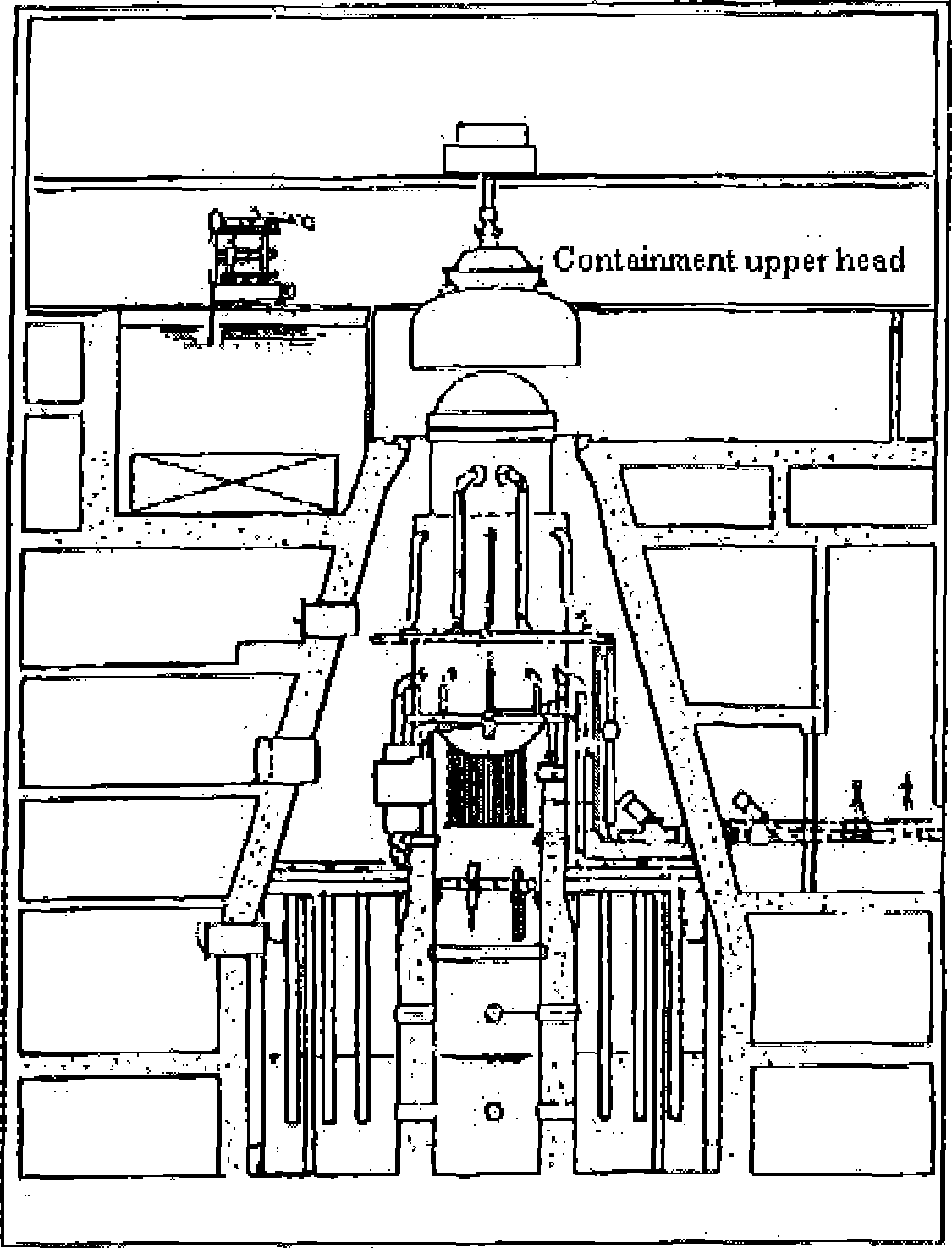
Removal of
RPV upper head
(1)
Preparations for reactor shutdown /cooling
(preparations
to cany in equipment/for work place)
(2)
Removal of well cover and slot plug
Removal of
reactor
c
ontainmenl
upp
er he
a
d
(4)
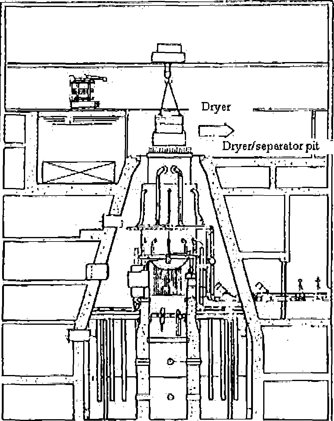
Removal and transfer of dryer
Figure
4.2.3 (1 )-(4) Schematic
diagram of major jobs related to reactor
4-
19
NSRA,
Japan

(5)
Water fill-up
of
reactor well and
diyer/separatorpit
Removal of
pool gate
Removal
and transfer of separator
(J)
(J)
Fuel transfer
@
Taking-out and maintenance of
MSIV
(MS
line plug in place)
■®
Taking-out and maintenance of MS relief-safety valve (MS line plugin
place)
(6)
Main
steam line plug
(with
support ring
for reverse
pressure)
Drainage
of main steam
line
Leaktest
and maintenance
of
MSIV
Maintenance of
main steam
relief-safety valve
(8)
Overhaul inspection of control rod drive mechanism
(after
fuel transfer)
'J
CRD
handUnS
devicfl
<
. 1
CRD automatic exchanger
®
CRD
reinoval/instaxation
device J
(|)
CRD cart
(j)
CRD repair room
Figure
4.2.3 (5)-(8) Schematic
diagram of major works related to reactor
NSRA,
Japan
4-20


Chapter
4 Operation and
Maintenance of BWR Plants
At this point, the main steam line plugs are attached to the main
steam nozzles of the RPV, enabling inspection and maintenance works
on the main steam isolation valves and main steam safetyrelief
valves in parallel with works on the core.
Fuel transfer and replacement of local power monitors
After opening the RPV, the spent fuel assemblies to be replaced with
fresh fuel assemblies during the periodic inspection and the fuel
assemblies around the control rods for which drive mechanisms are to
be inspected, the control rods (CRs) to be replaced, and the local
power monitors to be replaced are taken out and transferred to the
spent fuel pool. After these tasks, local power monitors and CRs are
replaced as required.
In handling fuel assemblies (both fresh and spent), the provisions
to provide safety measures (placards and preventive measures against
criticality, etc.) are observed.
Inspection and maintenance of control rod drive mechanisms, and
inspection of irradiated fuel assemblies
According to the long-term periodic inspection program, control rod
drive mechanisms (CRDs) scheduled to be inspected in the fiscal year
of concern are removed from the RPV, undergo their overhaul
inspections, and are installed again into the RPV (they may be
replaced with spare CRDs).
In parallel with this work, visual inspections are conducted in the
fuel pool on some of the irradiated fuel assemblies to be reused or
treated as spent fuel to confirm their integrity.
Fuel replacement, shuffling, and core inspection
When overhaul inspections of CRDs have been completed and CRs are
operable, the taken-out fuel assemblies are reloaded together with
fresh fuel assemblies according to a new fuel loading pattern. Fuel
shuffling is carried out in order to make fuel burnup as uniform as
possible.
After reloading fuel, it is confirmed using an underwater TV etc.
that fuel assemblies have been loaded correctly in the specified
locations.
Reactor restoration work and hydrostatic pressure test of the
reactor pressure vessel When jobs
involved with the core have been
completed, the RPV is
closed in reverse sequence to the RPV opening. Then,
a hydrostatic pressure test
of the RPV is performed to confirm the integrity, focusing on the
parts (mainly flanges) which were removed from the pressure boundary
of the pressure vessel and reinstalled during the periodic
inspection.
For this reason, jobs on the components to undergo overhaul
inspections among those related to the reactor must be completed by
the time of the hydrostatic pressure test of the pressure vessel
except for those of the RCCV.
Installation of RCCV upper head and leak rate tests
After the hydrostatic pressure test of the pressure vessel, the RCCV
upper head is installed, and all the penetrations and hatches are
restored and closed and the local leak rate tests are also
performed.
Then, the whole containment
vessel is pressurized with nitrogen gas, and the total leak rate
test is conducted to confirm the containment integrity.
Preparations for startup
With completion of the total leak rate test of the RCCV, all the
periodic inspection work activities centering on overhaul
inspections are completed and preparations for plant startup are
begun. Preparations include confirming completion of the periodic
inspection jobs and lining up each system so that it is appropriate
for plant operation. Also, by performing functional tests and
performance tests between systems in an integrated manner at this
time, it is confirmed that the plant can be operated safely.
When the predetermined inspections and maintenance and tests during
shutdown have been completed, the plant is started and its power is
increased to the rated power for performing the test operation.
Integrated load test
When the plant is at the rated power under stable operating
conditions, the integrated load test is performed to confirm that
the plant is stably operating with the predetermined performance. In
the case that the overhaul inspection of the turbine was performed,
its load and performance tests are performed at the same time.
With completion of the integrated load test, the periodic inspection
and licensee’s periodic inspection are complete.
4-21
NSRA,
Japan