

head volume is increased to make the temperature of the reactor
vessel head CRDM housing base about the same as the primary coolant
temperature at the reactor vessel inlet Inconel®-690
(690 class Ni-based alloy) is used for the material of
the reactor vessel head part mentioned above.
As a radical measure against SCC of the welded parts of the CRDM
pressure housing, structure without a canopy seal (a canopydess
structure) is employed as shown in Figure 3.12.2
Core internals of conventional PWRs consist of a baffle structure
made of stainless steel vertical plates (baffle plates) and
horizontal plates (former plates) connected by bolts. The total
number of the parts is about 4,000, of which about 2,000 are bolts.
The APWR employs radial neutron reflectors instead. The reflectors
have a simple structure consisting of 8 thick ring blocks made of
stainless steel. The total number of the parts is about 200, which
is much less than the number of the parts in the conventional PWRs
core internal and has an expected merit of enhanced reliability.
The reflectors and enlarged core, etc. of the APWR contribute to
enhancing neutron economy, saving of uranium resources (about 10%),
reduction
[Source]
“Improvement and Enhancement of Nuclear Reactor Technology"
Figure
3.12.2 Control rod drive mechanism pressure housing with the
canopydess structure
of fuel cycle cost (about 4%) and reduction of neutron radiation to
the wall of the reactor vessel possibly to about one-third of that
of conventional PWRs (4-loop).
The neutron reflector and the baffle structure are compared in
Figure 3.12.3.
Baffle
Structure Neutron Reflector
(Conventional
PWR) (APWR)
[Source]
Mitsubishi Heavy Industries Catalog "Mitsubishi
Improved PWR Power Plant”
Figure
3.12.3 Comparison of
neutron reflector and baffle structure
The steam generator of the APWR employs corrosion-resistant 690
class Ni alloy (Inconel®
-690) for the heat transfer tubes. The APWR steam
generator tube diameter is 3/4 inch; this size tube is actually used
overseas and smaller than the 7/8 inch diameter tube used for
Japanese conventional PWRs. The use of the smaller diameter tubes
can restrict increases of steam generator size to meet increased
power output.
Besides, an improved anti-vibration device with the number of
holding points increased from 6 to 9 is employed to enhance the
reliability to preclude fluid-induced vibration of U-shaped tubes.
A small and high performance steam-water separator and a one-step
high performance moisture separator are adopted to make the steam
generator total size smaller.
The major improvements of the steam generator are shown in Figure
3.12.4 and the main specifications are shown in Table 3.12.2.
NSRA,
Japan
J
-
130
Core internals


Steam generator
Chapter
3 Systems of PWR Nuclear Power Plants
Moisture
Separator
Steam-Water
Separator
Improved
Anti-Vibration Device
Anti-corrosion
Heat Transfer Tube (690 class Ni-based alloy (Inconel®-690)
(Small Size High
Performance)
[Source] Mitsubishi Heavy
Industries Catalog "Mitsubishi Improved PWR
Power
Generation Plants"
Figure
3.12.4 Improvements of APWR steam generator
Table
3.12.2
Main specifications of steam generator |
APWR |
Existing PWR (Replacement for current) |
Heat Transfer Area (m2) (per 1 unit) |
6,500 Approx. |
5,055 Approx |
Number of Heat Transfer Tubes (per 1 unit) Material Inside Diameter (mm) Thickness (mm) Tube Pitch (mm) |
5,830 690 class Ni-based alloy 17 Approx. 1.1 Approx. 2.7 Approx. |
3,382 Same as 20 Approx.
|
Anti-Vibration Device Holding Method |
9 point holding |
6 point holding |
Shell Outer Dia. (m) Upper Part Lower Part |
5.1 Approx. 3.9 Approx. |
|
Total Height (m) |
21 Approx. |
Same as |
3-
131
NSRA,
Japan
Reactor
coolant pumps
The APWR employs large reactor coolant pumps with better shapes
for the pump impeller and diffuser to enhance the pump
efficiency. A large ceramic shaft seal is employed to raise the
stability of the seal performance the sealing structure is
simplified by reducing the number of O-rings, and the O-ring
material is improved to extend the lifetime.
The major improvements of the reactor coolant pumps are shown in
Figure 3.12.5 and the
main specifications are shown in Table 3.12.3.
Shaft direction flow
diffuser
(with turning vane)
Radial direction discharge
diffuser
(without turning vane)
[Source]
Mitsubishi Heavy Industries Catalog "Mitsubishi Improved PWR
Plants"
Figure
3.12.5 APWR reactor coolant pump
Emergency core cooling
system
The ECCS of conventional PWRs consists of three systems:
accumulators, the high pressure safety injection system and the
low pressure safety injection system. In order to enhance the
ECCS reliability, the APWR simplifies the ECCS
configuration by employing high performance accumulators,
strengthens redundancy in the high pressure injection system and
eliminates switching of the water sources.
Comparisons of ECCS configurations are made in Figure 3.12.6
and Table 3.12.4.
Simplification of system configuration (Advanced accumulators)
The APWR employs advanced high performance accumulators in the
accumulator system (improved from conventional accumulators by
integrating the accumulator tanks and the low pressure safety
injection system) to inject cooling water into the core rapidly
in the event of a LOCA Thus, the ECCS for the APWR consists of
two systems, the high pressure injection system and the
accumulator system, whereas the conventional PWRs use three
systems, the accumulator system, the high pressure safety
injection system, and the low pressure safety injection system.
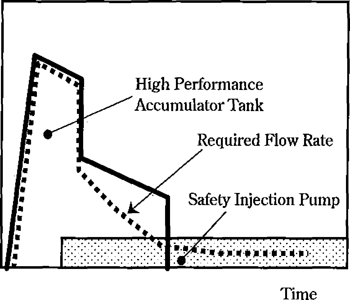
The high performance
accumulator of the APWR has a vortex-type damper installed inside
the accumulator tank which switches the injection flow passively
from a large flow rate to a small flow rate. The function of the
high performance accumulators is shown in Figure 3.12.7
and the mechanism for switching from large flow rate to reduced
flow rate is illustrated in Figure
Addition of this function eliminates the need for the pumps and
valves of the low pressure safety injection system which
simplifies the ECCS configuration and enhances the reliability
by precluding failures of these pumps and valves.
The accumulator tank consists of a stand pipe, vortex chamber,
etc. One of the two flow
Table
3.12.3 Main specifications of reactor coolant pumps |
APWR |
Conventional PWR (4-loop) |
Type (Catalogue No.) |
Vertial-shaft slant-flow(100A type) |
Vertical shaft slant flow (93A-1 type) |
Flow(m3/h) |
25,800 Approx |
20,100 Approx |
Head(m) |
89 Approx |
84 Approx |
Motor Shaft Power(kW) |
6,000 Approx |
4,500 Approx |
Dimensions (m) Height Casing Outer Dia |
8.4 Approx 2.3 Approx |
7.9 Approx 1.8 Approx |

NSRA,
Japan
3-
132
Chapter
3 Systems of PWR Nuclear Power Plants
Table
3.12.4 Emergency core cooling system configurations |
APWR |
Conventional PWR (4-loop) |
Accumulator |
33% x 4 |
Ditto |
Tank |
Accumulator Tank (Advanced Accumulator Tank) |
Accumulator Tank |
Type |
Vertical Pump, Cylinder Type |
Ditto |
Number |
4 |
Ditto |
Capacity (m3) |
90 Approx |
38 Approx |
High Pressure Injection System |
50% x 4 |
100% x 2 |
Pump |
Safety Injection Pump |
High Pressure Injection Pump |
Number |
4 |
2 |
Capacity (m3/h) |
300 Approx |
320 Approx |
Head(m) |
500 Approx |
960 Approx |
Low Pressure Injection Pump |
— |
100%x 2 units |
|
(Integrated in Accumulator System) |
(Shared with Residual Heat Removal System) |
Pump |
|
Heat Removal Pump |
Number |
|
2 |
Capacity (m3/h) |
|
1,020 Approx |
Head(m) |
|
91 Approx |
Emergency Water Source |
|
|
Refueling Water Pit |
|
|
Number |
1 |
Ditto |
Location |
Inside Reactor Containment |
Outside Reactor Containment |
Capacity (m3) |
2,300 Approx |
2,900 Approx |
entrances to the vortex damper center is located at the top of the
stand pipe (large flow entrance) and the other flow entrance is
located at its lower end (small flow entrance). When the water level
in the tank is higher than the entrance of the stand pipe for the
large flow rate, water enters from that entrance and merges with the
flow entering from the other entrance. The water flows straight
through the vortex chamber before exiting from the accumulator tank
through the exit nozzle at the center of the vortex chamber. In this
flow path, the flow rate can be large since the flow friction is
negligibly small. On the other hand, if the water level in the tank
drops and no water enters from the large flow entrance, water enters
only from the small flow entrance and it makes a whirlpool in the
vortex chamber before it flows out through the nozzle at the center
of the chamber. In this flow path, the rotating flow momentum is
changed to thermal energy in the pipe causing large friction and
reduced flow
injection results.
Reinforcement of redundancy of high pressure safety injection
system
Conventional PWRs have 2 trains of the high pressure safety
injection system; one train has the necessary water injection
capacity to maintain core integrity in a LOCA (100% x
2-train configuration). The high pressure safety injection system of
the APWR employs a configuration of 50% x 4 trains which increases
the margin for failures. Furthermore, the system independence is
enhanced because connecting pipes between trains are unnecessary.
Elimination of water source switching
Conventional PWRs have the refueling water storage pit, which is
also the ECCS water source, located outside of the reactor
containment. For long-term cooling after a LOCA the water source
must be
switched from the
refueling water storage pit to a recirculation sump installed in the
low part of the reactor containment vessel. In the
3-133
NSRA,
Japan
Low Pressure
SI
Pump (LP)
CSP
/-'J
High Pressure V SI
Pump (HP) Containment
O'
Spray Pump (CSP) Accumulator
U
Tank (ACC)
Recirculation
Sump
Refueling Water Storage Pit
APWR
Conventional
PWR (4-loop)
[Source] Mitsubishi
Heavy Industries Catalog “Mitsubishi
Improved PWR Plants”
Figure
3.12.6 ECCS configurations
Immediately
after Accident Initiation
Long-term
Core Cooling
Core
Re-flooded |
Long-term Core Cooling |
Core Re-flooded |

Injection
flow into core
Improved PWR
Conventional 4-loop
[Source] “Improvement
and Enhancement of Light Water Reactor Technology”
Figure
3.12.7 Function of the high performance accumulator tank
NSRA,
Japan
3-134

Chapter
3 Systems of PWR Nuclear Power Plants
Immediately after
Accident
Initiation!
(Injection with large flow
rate)
A
Few Minutes after
Accident Initiation
(Injection
with small flow rate)
Conventional
Accumulator
Tank
(Injection only with large
flow rate)
Nitrogen
Gas
[Source]
“Improvement and Enhancement of Light Water Reactor Technology”
Figure
3.12.8 Principle of flow switching in the high performance
accumulator tank
APWR, the refueling water storage pit as a water source of ECCS
is installed in the lower part
of die reactor
containment vessel. Switching of water source is therefore
unnecessary, that eliminates chances of miss-operation and
component failures in recirculation switching after accidents.
Other improvements
In conventional PWRs, ECCS water is injected into the reactor
vessel through the cold-leg
primary coolant system piping (except for 2-loop plants), but the
APWR design employs ECCS water injection directly into the
reactor vessel which provides cooling water to the core more
efficiently.
Reactor containment
facility
The APWR has a pre-stressed concrete containment vessel like
conventional PWRs (4-loop).
Table
3.12.5
Main specifications of reactor containment facility |
APWR |
Conventional PWR (4-loop) |
Reactor Containment Vessel Type Maximum Service Pressure (MPalgage]) Maximum Ser vice Temperatu re (C ) Major Dimensions(m) Inner Diameter/Inner Height Free Volume (m3) |
Cylinder with Upper Hemisphere 0.392 144 45.5 Approx/69 Approx 79,500 Approx |
Ditto Ditto Ditto 43 Approx/65 Approx 73,700 Approx |
Reactor Containment Vessel Spray System Pump Number Capacity (m3/h) Head(m) Iodine Removal Chemicals |
50% x 4 Containment Spray/ Heat Removal Pump 4 680 Approx 125 Approx Caustic Soda |
100% x 2 Containment Spray Pump 2 1,200 Approx 175 Approx Hydrazine | |


3-135
NSRA,
Japan