

from
open air
Safety
component rooms
air purification system
3-125
NSRA,
Japan
Figure 3.11.5 Auxiliary building heating, ventilating and air-conditioning system diagram (general & safety component rooms)

![]()

fro»
open air
lain
control rooi
enersency
ventilation
systea
Legend |
Iodine filter |
|
Particle fl 1ler |
[ fZf| |
Flal filler |
[r/fJ |
Rough filter |
|
Cold waler cooling col 1 |
|H/c| |
Steam heating coil |
lEH'd |
Electric heating coil |
|
Humidifier |
Dwr |
Automatic damper(air actuation) |
Hain
control rooa
air-conditioning
systea
outside air is supplied by the main control room emergency
circulation system which has filters to clean the air, when needed.
To the extent practicable, all the materials used in NPPs should be
either non-combustible or flame-resistant. Besides, combustible
components should be contained in physically separated areas. With
these provisions, the fire risk is minimized. However, assuming the
occurrence of unlikely fire incidents, fire alarm systems and fire
extinguishing systems are installed in NPPs.
The fire alarm and extinguishing system equipment is installed at
appropriate locations to detect fires at an early stage and to
extinguish them quickly and effectively, and to mitigate injury to
personnel and damage to plant equipment and structures, for the
purpose of ensuring the plant safety.
The fire protection system is designed in accordance with fire laws
and other applicable rules
and regulations. In addition, the fire protection system should be
designed so that the failures, malfunctioning, or miss-operation of
its components do not affect structures, systems and components
important to plant safety.
Descriptions of fire protection system equipment usually employed in
a PWR power plant are given in the subsections below.
Water fire extinguishing
systems
Water fire extinguishing systems are installed in the containment
building, the turbine building, the administration building, the
major transformer areas, etc. A flow diagram for a water fire
extinguishing system is shown in Figure 3.11.7.
CO2
Fire extinguishing systems
CO2 fire
extinguishing systems are installed in the reactor coolant pump
areas, the emergency diesel generator rooms, the fuel storage tank
area, the turbine main oil tank area, and some other areas.
NSRA,
Japan
3-126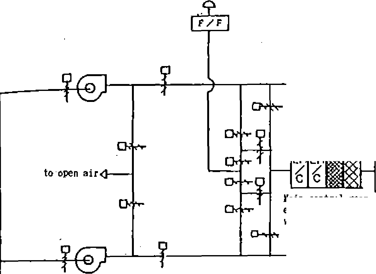
![]()
![]()

Figure 3.11.6 Auxiliary building heating, ventilating and air-conditioning system diagram (main control room)
Fire Protection System
Chapter
3 Systems of PWR Nuclear Power Plants
Figure
3.11.7
Water fire protection system diagram
Foam fire extinguishing
system
A foam fire extinguishing system is installed in the auxiliary
boiler fuel oil tank areas.
Portable fire
extinguishers
Portable fire extinguishers are installed in proper areas throughout
the plant in accordance with fire laws.
Fire alarm systems
Fire alarm systems are installed in all areas of the plant that
contain or present a fire hazard to equipment which are covered by
the fire protection system of the plant The
fire alarm systems detect fires either by temperature sensors or by
smoke sensors.
3-
127
NSRA,
Japan
Advanced Pressurized
Water Reactor (APWR)
The APWR was developed
as part of the third improvement and standardization program
(1981-1985). It was further improved to a large-scale advanced
light water reactor plant by integrating past experiences in
operation and maintenance and by introducing new advanced
technologies aimed at enhancement of safety, reliability and
operability, and reduction of radiation exposure, etc.
Objectives of Design
and Distinctive Features
The APWR (l,500MWe
class) utilizes the features of PWRs and adopts an enlarged core
with an increased uranium inventory of 30% from that of a
conventional l,200MWe class PWR. It has enlarged high
performance reactor coolant pumps, steam generators and a
turbine generator to realize electrical output of l,530MWe
while maintaining
the 4-loop design. Specifications of the APWR are shown in Table
3.12.1.
(1) Enhancement
of economy
The APWR has a core with 257 fuel assemblies increased from 193
assemblies of preceding PWRs (4-loop). It also has an increased
primary coolant flow rate, larger high performance primary
coolant pumps, steam generators and turbine-generator to attain
electrical output of l,538MWe. Figure 3.12.1
shows a schematic view of the arrangement of the steam
generators for the APWR
The APWR also uses stainless steel radial neutron reflectors
around the enlarged core to reduce neutron leakage from the core
and it uses Zircaloy fuel supporting grids in the fuel assembly
structures which has less neutron absorption. These
modifications allow uranium enrichment of fuel to be lowered
which saves uranium resources compared with conventional PWRs.
Table
3.12.1 Basic specifications of APWR |
APWR |
Conventional PWR (4-loop) |
|
Electrical Power (MW) |
— 1,538 |
—1,180 |
|
Reactor Thermal Power (MW) |
4,466 |
3,423 |
|
Core |
Number of Fuel Assemblies |
257 |
193 |
Fuel Rod Array |
17 x 17 |
Same as |
|
Fuel Loading© |
— 121 |
— 91 |
|
Average Linear Power(kW/m) |
— 17.6 |
— 17.9 |
|
Active Core Height (m) |
— 3.7 |
Same as |
|
Core Equivalent Diameter (m) |
— 3.9 |
— 3.4 |
|
Primary Coolant System Number of Loops |
4 |
Same as |
|
Operating Pressure MPa (gage) |
— 15.4 |
Same as |
|
Reactor Coolant Temp. |
Core Inlet(°C) |
— 289 |
Same as |
Core Exit(°C) |
— 325 |
Same as |
|
Reactor Vessel |
Inside Diameter(m) |
— 5.2 |
— 4.4 |
Inside Height(m) |
— 13 |
Same as |
|
Steam Generator |
Type (Catalogue No.) |
70F-1 |
52F |
Number |
4 |
Same as |
|
Heat Transfer Area (m2) |
— 6,500 |
— 4,870 |
|
Main Steam Pressure MPA (gage) (*) |
— 6.03 |
Same as |
|
Main Steam Temperature (°C) (*) |
— 277 |
Same as |
|
Steam Generation (per unit) (t/h) (*) |
— 2,200 |
—1,700 |
|
Reactor Coolant Pump |
Type (Catalogue No.) |
100A |
93A-1 |
Number |
4 |
Same as |
|
Rated Flow Rate (per unit) (m3/h) |
— 25,800 |
— 20,100 |
|
Motor Output (per unit) (kW) |
— 6,000kW |
- 4,500kW |
|
Steam Turbine |
Type (Catalogue No.) |
TC6F54 |
TC6F44 |
Low Pressure Turbine |
— 1,375 |
-1,118 |
|
Last Stage Blade Length (mm) |
— 54 inch |
— 44 inch |
|
Generator |
Capacity (MVA) |
—1,715 |
—1,310 |
(*)At
rated power
NSRA,
Japan
3-128