

Decontamination
faciIity
Steam
line
Makeup
water
Legend
Figure
3.11.2 Auxiliary steam system diagram
NSRA,
Japan
3
122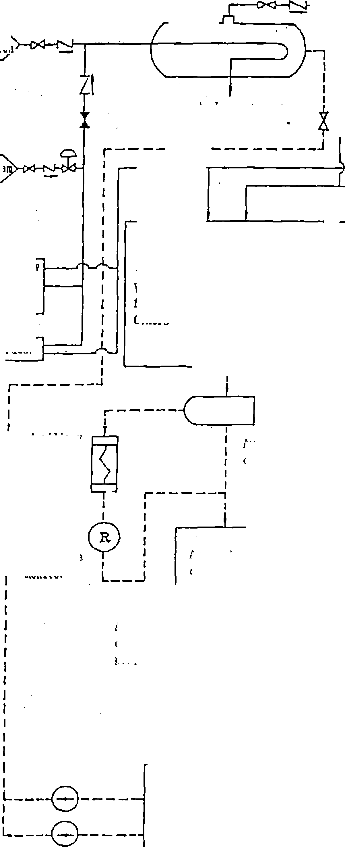
![]()

Drain line
Chapter
3 Systems of PWR Nuclear Power Plants
Main
steaa relief valve
driven
driven
Other
control valve for turbine
B
class
Air
dryer
Station
air
aux.
feedwater puip
aux.
feedwater puip
Air
compressor
Air
reservoir
relief
valve
4)
B
class
Air
dryer
Turbine
bldg.
Outdoor
Air
supply to outdoor
Pressurizer
relief valve
Air
supply to containment
Air
supply to
reactor
building
A
aux.
building
Air
supply for hydrogen purging
supply
to
reactor
building
1
aux. building
Air
supply to turbine
hall
As
class
Air
supply to reactor building
&
aux. building
Figure
3.11.3 Instrument air system diagram
Air
supply
for hydrogen
purging
Air
compressor
(1) System composition and
functions
Composition
The heating, ventilating and air conditioning systems include mainly
a containment heating, ventilating and air conditioning system, an
auxiliary building heating, ventilating and air conditioning system,
the annulus clean-up system, and the safeguard component area
clean-up system.
The annulus clean-up system and the safeguard component area
clean-up system are considered as integral parts of the engineered
safeguard systems and have already been discussed in Section 3.7.
They will not be further described here.
Functions
Maintain desired environmental conditions for plant personnel
regarding radiation control
The heating, ventilating and air conditioning systems supply fresh
air for the plant personnel during the plant normal operation and
after accidents. These systems reduce the radiation
levels in the plant buildings, by removing radioactive materials in
the atmosphere in the buildings.
Maintain desired environmental conditions for plant components and
electrical systems
The heating, ventilating and air conditioning systems maintain
desired environmental conditions such as suitable temperature
necessary for the functioning of plant components and electrical
systems during the plant normal operation and after accidents.
Maintain habitable conditions in control rooms
The heating, ventilating and air conditioning systems maintain
desired environmental conditions, such as moderate temperature, in
the main control room and other areas of the plant where operators
and workers stay for long times.
(2) Containment heating,
ventilating and air conditioning system
The containment heating, ventilating and air conditioning system
consists of a containment air conditioning system, a containment air
recycling
3-123
NSRA,
Japan
Sieaj control valve for turbine
Inside containment
Heating, Ventilating and Air Conditioning Systems
system, and a containment air clean-up system. Hie
containment heating, ventilating and air conditioning system is
schematically illustrated in Figure 3.11.4.
i) Containment air conditioning system
The containment air conditioning system is used to ventilate the
containment vessel during the plant shutdown operation, and to
support operators and maintenance staff entering it The
containment air conditioning system consists of a containment
purge supply system and the containment exhaust system.
Containment purge supply system
The containment purge
supply system consists of containment purge supply
units and containment purge supply fans. The containment purge
supply units include steam heating coils for maintaining the
containment vessel temperature above 21X"
even in winter. Two isolation valves are installed in series on
the supply header duct penetrating the containment wall.
Containment exhaust system
The containment
exhaust system consists of containment exhaust filter
units and containment exhaust fans. The
containment exhaust filter units include particulate filters to
remove dust particles from the exhaust air. Two isolation valves
are
installed in series on the exhaust header duct penetrating the
containment wall.
Containment air recycling system
The containment air
recycling system consists of containment air recycling
units and containment air recycling fans. Hie
containment air recycling units contain cooling coils for
maintaining containment vessel
temperature below approximately 50°C
during the plant normal operation.
Containment air clean-up system
The containment air
clean-up system consists of containment air clean-up
filter units and containment air clean-up fans. The containment
air clean-up filter units contain particulate filters to remove
dust particles, and iodine filters to remove iodine from the
containment air. Hie
containment air clean-up system is used to clean up the
containment air and to reduce the concentration of radioactive
materials in it allowing safe access of operators to the
containment vessel during the plant normal operation.
(3)Auxiliary
building heating, ventilating and air conditioning system The
auxiliary building heating, ventilating and
Legend |
Iodine filter |
|
Particle filter |
|F/F| |
Fiet filter |
t" / f ] |
Rough filter |
|czc| |
Cooling coil |
L<hZcj |
Electric heating coil |
[EZD |
Steam heating coil |
|
Steam reheating coil |
o |
Automatic daropcr(Air actuation) |
|
Automatic butterfly valve (Air actuation, non leakage type) |

Figure
3.11.4 Containment heating, ventilating and air-conditioning system
diagram
NSRA,
Japan
3-124

![]()
Chapter
3 Systems of PWR Nuclear Power Plants
air conditioning system consists of systems such as an auxiliary
building air conditioning system and a main control room air
conditioning system. The auxiliary building heating, ventilating
and air conditioning system is schematically illustrated in
Figure 3.11.5 and Figure 3.11.6.
Auxiliary building air conditioning system
The auxiliary building air conditioning system consists of an
auxiliary building purge supply system and an auxiliary building
exhaust system. It ventilates the auxiliary building air during
the plant normal operation.
Auxiliary building purge supply system
The auxiliary building
purge supply system consists of auxiliary building
purge supply units and auxiliary building
purge supply fans. The auxiliary building purge supply units
contain steam heating coils to maintain the auxiliary building
temperature above lOt
during winter.
Auxiliary building exhaust system
The auxiliary building
exhaust system consists of auxiliary building exhaust
filter units and auxiliary building exhaust fans. Hie
auxiliary building exhaust filter units contain particulate
filters to remove dust particles from the exhaust air.
Main control room air conditioning system
The main control room
air conditioning
system consists
of a main control room air conditioning system and a main control
room emergency recirculation system for maintaining the main
control room habitability.
Main control room air conditioning system
The main control room
air conditioning system consists of main control room
air conditioning units, main control room air conditioning fans,
heaters, humidifiers and main control room circulation fans. The
main control room air conditioning units contain cooling coils
for air conditioning of the main control room. The main control
room air conditioning system circulates the air in the control
room and takes in some outside air during the plant normal
operation.
Main control room emergency circulation system
The main control room
emergency circulation system consists of a main
control room emergency circulation filter unit and main control
room emergency circulation fans. The main control room emergency
circulation filter unit consists of particulate filters to remove
dust particles and iodine filters to remove iodine from the main
control room air; these are intended to reduce the radiation
exposures of control room operators after accidents. During
accidents, the normal outside air in-take line is closed, and the
Legend |
Particle filter |
|f^f| |
Flat filler |
|r/f| |
Rough filter |
|
Steam heating col 1 |
Wvtl |
Steam reheating coil |
O-w>- |
Automatic damper (air actuation) - |