

- •Introduction for English Version
- •Toshiaki Enomoto
- •Foreword
- •Table of Contents
- •Xj nsra, Japan
- •X;;; nsra, Japan
- •Chapter 5
- •Chapter 6
- •Chapter 1 General
- •History of Nuclear Power Plant Development
- •Experiences in Nuclear Power Generation and Safety Research
- •Comparison of Schemes of Nuclear and Thermal Power Generation
- •Effective Reactor Fuel Loading
- •Reactor Self-Regulation Characteristics
- •Reactor Decay Heat
- •Confinement of fPs
- •Reactor Steam Conditions
- •Safety Design Principles for npPs
- •Prevention of Occurrence of Abnormal Conditions (Level 1)
- •Figure 1.4.1 Defense-in-Depth philosophy
- •Prevention of Expansion of an Abnormal Event (Level 2)
- •Prevention of Abnormal Release of Radioactive Materials and Mitigation of Consequence (Level 3)
- •Emergency core cooling system
- •Confinement of radioactive materials by five barriers
- •Outline of Laws, Regulations and the Regulatory Framework
- •Domestic Framework
- •Permit to establish a power generating reactor
- •Sanction of the construction plan
- •Approval of technical specifications
- •Regulations after start of commercial operation
- •Iaea Safety Standards
- •Figure 1.5.4 Structure of iaea safety standards
- •Chapter 2 Systems of bwr Nuclear Power Plants
- •General Design Philosophy
- •Fuel Rods
- •Reactor Core
- •Reactor Coolant Pressure Boundary
- •Engineered Safety Features
- •Instrumentation and Control System
- •Other Systems
- •Plant Layout
- •Plot Plan
- •Grade level planning
- •Configuration of the buildings
- •Road planning
- •Pipe conduits and electric cable conduits planning
- •Construction area planning
- •Harbor and water intake/discharge planning
- •Other considerations
- •Main Buildings and Auxiliary Buildings
- •Figure 2.2.2 Overall plant layout of a bwr npp
- •Reactor building
- •Turbine building
- •Figure.2.2.7 Main building arrangements (two-unit site)
- •Main control room (Control building)
- •Radioactive waste treatment facility building
- •Service building
- •Exhaust stack
- •Advanced boiling water reactor (abwr) plant arrangement
- •Nuclear Reactor and Core
- •Fuel Rod and Fuel Assembly
- •Structure of fuel rod and fuel assembly
- •Figure 2.3.1 9x9 Fuel assembly (a type) and fuel rod structure (example)
- •Fuel rod and assembly designs
- •Reactor and Reactor Core
- •Structure of reactor and reactor core
- •Figure 2.3.4 Internal structure of a reactor pressure vessel (cut out view)
- •Vessel (rpv)
- •Incore monitor housing
- •Hpcf sparger top Fuel guide—
- •Reactivity control system
- •Core Design
- •Figure 2.3.20 Control rod with the maximum reactivity worth
- •Core stability
- •Operation and management of the core
- •Primary Coolant System
- •System Summary
- •Primary loop recirculation (plr) system
- •Main steam (ms) system
- •Feed water (fdw) system
- •Key Components
- •Reactor pressure vessel (rpv)
- •Figure 2.4.3 Control rod drive mechanism and in- core monitor housing
- •Recirculation pumps
- •Safety relief valve (srv)
- •Turbine System
- •System Summary
- •Main Turbine System and Auxiliary Equipment
- •Iypes of nuclear plant steam turbines
- •Steam turbine
- •Moisture separator and heater
- •Electro-hydraulic turbine control (ehc) unit
- •Main Steam System and Condensate Feed Water System
- •Main steam line and turbine bypass system
- •Steam extraction system and feed water heater drain system
- •Condenser and circulating water system
- •Condensate and feed water system and condensate cleanup system
- •Instrumentation and Control System
- •Reactor Instrumentation and Control System
- •Plant control system
- •Reactor neutron monitoring system (nms)
- •0 Source range monitor (srm) 4 detectors q Power range monitor (prm) 43x4detectors
- •Main Control Room
- •Structure and functions of control panels
- •3BbBia3b3jjsbj5ca;nS1ss!aacBa3caoanoDaj3j;|
- •Remote shutdown system (rss)
- •Emergency operational facilities
- •Process Instrumentation System
- •Reactor process instrumentation system
- •Figure 2.6.14 Reactor water level and pressure instrumentation
- •Radiation monitoring system
- •2.7 Engineered Safety Features
- •Design Policy of Engineered Safety Features
- •Basic safely philosophy
- •Philosophy to prevent occurrence of serious incidents
- •Philosophy to mitigate serious incidents
- •Emergency Core Cooling System (eccs)
- •Roles of the eccs
- •Criteria for design and evaluation of eccs
- •Design policies for the eccs
- •Eccs configuration
- •Eccs configuration of an abwr
- •Reactor Containment Facility
- •Roles of reactor containment facility
- •Primary containment vessel (pcv)
- •Containment spray system (css)
- •Flammable gas control system (fcs)
- •Standby gas treatment system (sgts)
- •Reactor containment facility of an abwr
- •Reactor Auxiliary Systems
- •Residual Heat Removal (rhr) System
- •Operating modes
- •System functions and configuration
- •Reactor Core Isolation Cooling (rcic) System
- •System functions and configuration
- •Reactor Water Cleanup (cuw) System
- •System functions and configuration
- •Key components and features
- •Fuel Pool Cooling and Cleanup (fpc) System
- •System functions and configuration
- •Figure 2.8.8 cuw pump (canned motor type)
- •Reactor Building Cooling Water (rcw) System and Reactor Building Cooling Seawater (rcws) System
- •System functions and configurations
- •Key components and features
- •Figure 2.8.10 Basic concept of rcw and rcws systems (example)
- •Fuel Handling and Storage System
- •Spent fuel storage pool
- •Cask pit
- •Refueling machine
- •Radioactive Waste Treatment Systems
- •Gaseous Waste Treatment System
- •Figure 2.9.1 a typical flow sheet of gaseous wastes treatment system (Example of a 1,100 mWe bwr plant)
- •Liquid Waste Treatment System
- •Solid Waste Treatment System
- •Generator excitation system
- •Major Transformers and Switchyard System
- •Major transformers
- •Switchyard system
- •Plant Auxiliary Power System
- •Plant auxiliary power supply system
- •Emergency diesel generator system
- •Direct current (dc) power supply system
- •Instrumentation and control power supply system
- •Plant Auxiliary Systems
- •Plant Water System
- •Plant water treatment system
- •Make-up water system
- •Auxiliary Steam System (House Boiler System)
- •Design philosophy
- •Key equipment
- •Compressed Air Supply System
- •Design philosophy
- •Key equipment
- •Heating, Ventilating and Air Conditioning (hvac) System
- •Design philosophy
- •Key equipment
- •Figure 2.11.6 Outline of hvac system of the turbine building
- •Figure 2.11.7 Outline of hvac system of the main control room
- •Fire Protection System
- •Key equipment
- •Advanced bwr (abwr)
- •Design Principles
- •Enhanced safety and reliability
- •Figure 2.12.2 Reactor buildings (a 1,100 mWe bwr and an abwr)
- •System design
- •Advanced core
- •Reactor system
- •Reinforced concrete containment vessel (rccv)
- •Turbine system
- •Enhanced Safety
- •Improved reactor shutdown capabilities
- •I turbine driven reactor feedwater pump||
- •Figure 2.12.8 abwr safety features
- •Enhanced reactor cooling capability
- •Enhanced capability for containing radioactive materials
- •Overall safety
- •Figure 2.12.10 abwr eccs (three divisions)
- •Enhanced Operability and Maneuverability
- •Improved monitoring and maneuverability
- •Enhanced operability
- •Chapter 3 Systems of pwr Nuclear Power Plants
- •General Design Philosophy
- •Fuel Rods
- •Reactor Core
- •Engineered Safeguard Systems
- •Instrumentation and Control System
- •Other Systems
- •Plant Layout
- •Plot Plan
- •Intake and discharge structures
- •Switchyard
- •Reactor building and reactor auxiliary building
- •Turbine building
- •Water supply and treatment system
- •Radioactive waste storage building
- •Cask storage building
- •Harbor facilities
- •Access control system
- •Equipment Arrangement
- •Reactor building
- •Reactor auxiliary building
- •Turbine building
- •Fuel handling and storage building and facilities
- •Plant Layout Considerations
- •Building composition
- •General requirements of plant layout design
- •Decontamination Pi t
- •Isolation Valve
- •2 Loop Plant
- •3 Loop Plant
- •Figure 3.2.7 Buildings configurationn of nuclear power plants in japan
- •Figure 3.3.1 Schematic of fuel assembly and fuel rod
- •Structure of the fuel rods and fuel assemblies
- •Design of fuel rods and fuel assemblies
- •Figure 3.3.2(2) Support grid structure (2)
- •Reactor and Reactor Core
- •Structure of reactor and reactor core
- •Dynamic characteristics of the nuclear reactor
- •Core stability
- •Reactivity control
- •Figure 3.3.13 Critical boron concentration vs. Burnup (hot full power (hfp), all rods out)
- •Power distribution control
- •Figure 3.3.15 Reactivity worth of control group bank d (beginning of cycle, hot zero power, no xenon; example 4-loop core)
- •Figure 3.3.16 Structure of primary neutron source assembly
- •Figure 3.3.17 Structure of secondary neutron source assembly
- •Core management
- •Reactor Coolant System
- •Outline
- •System summary
- •System functions
- •Main Components
- •Reactor vessel
- •Steam generators
- •Pressurizer
- •Vertical u-lube type heat exchanger 7.D8 mPa [gage]
- •17.16 MPa (gage]
- •Reactor coolant piping
- •Reactor coolant pumps
- •IVol. Seal
- •Turbine System
- •Outline
- •Main Turbine and Its Appurtenances
- •Characteristics of Nuclear Power Plant Turbines
- •Turbine types, blade designs and steam cycles
- •Structures of turbines
- •Table 3.5.2 Turbine type and applicable output
- •Turbine governor system
- •Turbine steam inlet valves
- •Turbine protection system
- •Main Steam System
- •Main steam safety and relief valves
- •Main steam isolation and check valves
- •Turbine bypass valves
- •Condensate, Feedwater System and Other Related Systems
- •Condensate, feedwater system
- •Auxiliary feedwater system
- •Circulating water system
- •Instrumentation and Control System
- •Reactor Instrumentation and Control System
- •10 5 Neutron Source Range Trip Point
- •Figure 3.6.1 Out-of-core nuclear instrumentation range of measurement
- •High Neutron Flux {Power Range High Selling)
- •Sleam Generator Feedaler Flow Level tl *
- •Interlock
- •Reactor
- •Turbine Load Neutron Flux Level
- •Injection Pump Actuation
- •2/4 Logic
- •Figure 3.6.6 Pressurizer pressure protection and control system
- •Reactor control system
- •Figure 3.6.11 Feedwater control system
- •Main Control Room
- •Composition of main control board
- •Methods for monitoring and operation
- •Alarm system
- •(1) Vdu monitor operation example of the screen (system screen)
- •(2) Vdu monitor operation example of the screen (control screen)
- •(3) Vdu monitor operation example of the screen (screen monitors only)
- •Operator assisting system
- •Plant operation management
- •Reactor shutdown panel outside the main control room
- •Emergency support plan
- •Process Instrumentation System
- •Primary system
- •Secondary system
- •Radiation Monitoring System
- •Process radiation monitors
- •Area monitors
- •Radiation measurement during accidents
- •Engineered Safety Feature
- •Systems and Their Functions
- •Emergency core cooling system (eccs)
- •Reactor containment facility
- •Containment spray system
- •Annulus air clean-up system
- •Safety component room air clean-up system
- •General points
- •Emergency Core Cooling System (eccs)
- •Functions
- •System configuration
- •Reactor Containment Facility
- •Functions and configuration
- •Functions and structure of the different containment vessels
- •External shield building
- •Annulus
- •Containment Spray System
- •Function
- •System configuration
- •Iodine removal chemicals tank
- •Functions
- •Components
- •Safety Component Area Air Clean-up System
- •Functions
- •Components
- •Reactor Auxiliary Systems
- •Chemical and Volume Control System (cvcs)
- •System composition and functions
- •Inside coo tai oment
- •Injection pump —:—
- •Components
- •Residual Heat Removal System (rhrs)
- •System composition and functions
- •Component cooling water |m1
- •Components
- •Component Cooling Water System (ccws)
- •System composition and functions
- •Components
- •Instrument air compressor a
- •Instrument air cos pressor b
- •I .Aurillary components,
- •I [important for safetyj
- •Sea Water System (sws)
- •Spent Fuel Pit Cooling and Clean-up
- •Fuel Handling System
- •Radioactive Waste Disposal System
- •Gaseous Waste Disposal System
- •Liquid Waste Disposal System
- •Figure 3.9.4 Boron recycle system evaporator (immersion heater type)
- •Solid Waste Disposal System
- •Electrical Systems
- •Main Generators and Appurtenances
- •Appurtenances of the main generators
- •Generator excitation system
- •Voltage regulator
- •Major Transformers and Transmission System
- •Generator load break switch (glbs)
- •Switchyard
- •Plant Auxiliary Power Supply
- •Figure 3.10.4 Switchyard bus composition
- •311 Power transformer
- •Dc power supply systems
- •Instrument power systems
- •Figure 3.10.6 Direct current power supply system (one of safety system)
- •Board feu | 4 c Icard for j I c
- •(Note)Wllh mechanical Interlock
- •Compressed Air Systems
- •Drain line
- •Sieaj control valve for turbine
- •Inside containment
- •Heating, Ventilating and Air Conditioning Systems
- •Figure 3.11.5 Auxiliary building heating, ventilating and air-conditioning system diagram (general & safety component rooms)
- •Figure 3.11.6 Auxiliary building heating, ventilating and air-conditioning system diagram (main control room)
- •Fire Protection System
- •Figure 3.12.1 Schematic view of apwr steam generators
- •Enhancement of reliability
- •Improvement of operability
- •Reduction of radiation exposure
- •Plant Design
- •Core internals
- •Steam generator
- •Instrument and control system
- •Turbine generator
- •Conclusion
- •Chapter 4 Operation and Maintenance of bwr Plants
- •Plant Operation
- •Plant Startup
- •Figure 4.1.1 Schematic diagram of bwr plant system
- •Figure 4.1.2 Startup curve after periodic inspection
- •Figure 4.1.3 Operating range of core thermal power and core flow
- •Normal Plant Operation
- •Implementing surveillance tests
- •Core management during operation
- •Chemistry control during plant operation
- •Other operational activities
- •Plant Shutdown
- •Chemistry control during plant shutdown
- •Plant Maintenance
- •Figure 4.2.1 Administrative classification of maintenance
- •Periodic Inspections and Licensee’s Periodic Inspections
- •Periodic inspections
- •Licensee’s periodic inspections
- •Time to carry out licensee’s periodic inspections (including the periodic inspections) and periodic checks
- •Items for the periodic inspections and licensee’s periodic inspections
- •Procedure and Work Schedule of Periodic Inspections
- •VII) Preparations for startup
- •IV) Fuel exchange & shuffling
- •VI) pcv upper head Qf ’
- •Other major work activities
- •Figure 4.2.4 Reactor recirculation pump
- •Contents of isIs
- •Remote automatic ultrasonic testing device for isIs
- •Checks and Maintenance during Plant Operation
- •Switching components during operation
- •Maintenance during operation
- •Efficiency Improvement of Periodic Inspection Work
- •Improvement of plant layout
- •Reduction of the time needed for the periodic inspection
- •Maintenance Against Plant Aging
- •Technical Study on Aging
- •Upgrading of evaluation technology
- •Maintenance Technology against Aging
- •Figure 4.3.3 Concept of seal weld
- •Figure 4.3.5 Core shroud tie rod
- •Figure 4.3.8 Principle of crc
- •Figure 4.3.11 Conceptual diagram of wol pipe cross section
- •Upgrading by Facility Replacement
- •Chapter 5 Operation and Maintenance of pwr Plants
- •Plant Operation
- •Reactor Control Systems
- •Control rod control system
- •Turbine bypass control system
- •Pressurizer pressure control system
- •Pressurizer water level control system
- •Steam generator water level control system
- •Plant Startup
- •Plant Normal Operation
- •Operator Activities during Plant Normal Operation
- •Plant Shutdown
- •Chemistry Control
- •Outline of chemistry control of primary system
- •Outline of chemistry control of secondary system
- •Management of waler trealment chemicals
- •Sg blow down water recovery system
- •Plant Maintenance
- •Maintenance Management Policy
- •Periodical Inspections and Periodical Utility Inspections
- •Figure 5.2.2 Framework of plant in-service inspection system
- •Major activities in the periodical inspection period
- •0Utline of other major activities
- •Table 5.2.2 Overhaul inspection required by regulations
- •Maintenance during plant normal operation
- •Checks during plant normal operation
- •Maintenance dining plant normal operation
- •Rationalization of Plant Features Related to Periodical Inspections
- •Optimization of plant equipment arrangement
- •Reduction of durations for periodical inspections
- •Reduction of radiation dose
- •Maintenance to Cope with Plant Aging
- •Technical Evaluation of Aging Effects
- •Maintenance Techniques to Cope with Plant Aging
- •Maintenance of Alloy 600
- •Upgrading of Plants by the Renewal of Systems
- •Chapter 6 Radiation Control
- •Purposes of Radiation Protection
- •Regulation for Radiation Protection
- •Legislative System for Radiation Protection
- •Specific Applications of Legislation
- •Industrial Safety and Health Law
- •Radiation Sources at npPs
- •Actual Conditions concerning Radiation Sources
- •Figure 6.3.1 (1) Trends in dose equivalent rates of the bwr plr system piping
- •Area Control
- •Standards of Area Control in Accordance with Legislation
- •Confirmation of Radiation Environment
- •Access to and Exit from Controlled Areas
- •Work Management
- •Study of Work Methods
- •Approval of Radiation Work
- •Confirmation of Work Environment
- •Completion of Work
- •Fundamentals of Radiation Protection for Work Management
- •6.7 Controls of the Individual
- •Qualification of Radiation Workers
- •Evaluation of Individual Dose
- •Target of Individual Dose Control
- •Records of Individual Dose
- •Track Record of Individual Dose
- •Figure 6.7.1 History of the number of npPs, number of radiation workers, and total dose in Japan (excluding gcr)
- •Fiscal year Figure 6.7.5 Trends in annual average total doses per npp in major counties
- •Radioactive Waste Management
- •Radioactive Solid Wastes
- •Radioactive liquid Wastes
- •Figure 6.8.3 Trends in total amount of solid wastes stored as of the end of each fiscal year (for each type of light water reactor) and the number of drums sent to the Rokkasho Center
- •Tire level to classify the "materials not required to heat as radioactive materials" as the radioactivity is low enough
- •Figure 6.8.5 Outline of the clearance system
- •Fiscal year
- •Figure 6.8.6 Trends in discharged radioactivity of radioactive liquid wastes (excluding tritium) (total discharge for each reactor type)
- •Fiscal year
- •Environmental Radiation Monitoring
- •Chapter 7 Safety Evaluation of
- •Bwr Plants
- •Basic Policy for Safety Evaluation
- •Objectives of Safety Evaluation
- •Anticipated Operational Occurrences
- •Assumption of Event
- •Abnormal Withdrawal of Control Rods during Reactor Startup
- •Loss of Feed Water Heater
- •Loss of Load
- •Features of abwr Transient Analysis
- •Accidents
- •Assumption of Events
- •Loss of Reactor Coolant (in case of a Large Break)
- •Time after the accident (s)
- •Characteristics of abwr Accident Analysis
- •Major Accidents and Hypothetical Accidents
- •Assumption of Events
- •Loss of Reactor Coolant
- •Main Steam Line Break
- •(Note) These numbers are to be used for the whole body dose evaluation together with those of noble gases.
- •Figure 7.4.2(1) Process of iodine release during the main steam line break (major accident)
- •Dose Evaluation
- •(Note) These numbers are to be used for the whole body dose evaluation together with those of noble gases.
- •Probabilistic Safety Assessment (psa) for bwRs
- •Psa during Operation
- •Figure 7.5.1 Contribution of each sequence to the core damage frequency
- •Psa during Shutdown
- •Severe Accident
- •Chapter 8 Safety Evaluation of
- •Pwr Plants
- •Basic Principles for Safety Evaluation
- •Purposes of Safety Evaluation
- •Methodology for Safety Evaluation
- •Abnormal Transients during Operation
- •Postulation of Events
- •Partial Loss of Reactor Coolant Flow
- •Figure 8.2.1 Partial loss of reactor coolant flow (• indicates the initial value)
- •Uncontrolled Control Rod Withdrawal at Reactor Startup
- •Loss of Normal Feedwater Flow
- •Figure 8.2.2 Uncontrolled control rod withdrawal at reactor startup (•Indicates the initial value)
- •Accidents
- •Postulation of Events
- •Loss of Reactor Coolant
- •Steam Generator Tube Rupture
- •Major Accidents and Hypothetical Accidents
- •Postulation of Events
- •Loss of Reactor Coolant
- •Steam Generator Tube Rupture
- •Release from fuel rods to the reactor system
- •Release from the primary system to the secondary system
- •Release into the atmosphere
- •Probabilistic Safety Assessment (psa) for pwr Plants
- •Outline of Probabilistic Safety Assessment
- •Use of psa for safety management in the shutdown state
- •Chapter 9 Siting
- •Site Assessment
- •Site Conditions
- •Procedures for Site Assessment
- •Environmental impact assessment
- •Preliminary public hearing
- •Designation of important electric power development area
- •Basic Philosophy of Site Safety
- •Site Review Procedures and Contents
- •Hie Concept of Site Safety in the iaea Site Safety Standard
- •Reactor Site Criteria in the u.S.
- •Siting Philosophy
- •Site Assessment
- •Procedure for Radiation Effect Evaluation
- •Nuclear Emergency Preparedness
- •Seismic Safety
- •Basic Policy on Seismic Design
- •Figure 9.5.1 Formulation flow chart of design basis earthquake ground motion Ss ote£g)
- •Elastically design earthquake ground motion Sd (edegmSd)
- •Seismic Assessment
- •In the equipments
- •Seismic assessment of equipment and piping system
- •Maritime Environment Protection
- •The Effects of Thermal Effluent
- •Hie Effects of Coastal Structures
- •Advanced Siting Concept
- •General
- •Need for qa Activities in Nuclear Power Plants (npPs)
- •Addressing qa
- •International Trends in qa Activities for npPs
- •Development of Commercial qa Standards in Japan
- •1996 (Country taking part in un)
- •Establishment of jeac4111-2003
- •Quality Management System (qms)
- •Figure 10.2.2 Process diagram on npp (example)
- •Stipulation of qms
- •Provision of quality policy and quality objectives
- •Presentation of evidence of effective operation of qms
- •Document Control
- •Record Control
- •Management Responsibility (Top Management)
- •Quality Policy and Quality Objectives
- •Management Representative
- •Review by Management (Management Review)
- •Table 10.3.2 Three outputs on management review
- •Education and Training (Human Resources)
- •Product Realization Planning (Work Planning)
- •Product Realization Planning (Work Planning)
- •Noncon forming action/corrective action
- •Preventive action
- •Relationship with Customer
- •Determination and Review of Requirements related to the Product (Work)
- •Customer Communication and Customer Satisfaction
- •10.6 Design and Development
- •Planning of Design and Development
- •Verification
- •Validation
- •Figure*! 0.6.1 Process flow of design and development
- •Inputs to Design and Development
- •Outputs from Design and Development
- •Review of Design and Development
- •Table 10.6.2 Examples of verification items in the design review
- •Verification of Design and Development
- •Validation of Design and Development
- •Configuration Management of Design and Development
- •Purchasing
- •Purchasing Process
- •Communication with Suppliers
- •Purchasing Requirements
- •Verification of Purchased Products
- •Table10.7.1 Examples of purchase requirements
- •10.8 Production and Service Provision (Implementation of Work)
- •Control of Production and Service Provision (Control of Work)
- •Validation of Processes
- •Analysis of data and improvement (Sec.10.10)
- •Analysis of data
- •Nonconforming action / corrective action
- •Preventive action
- •Table 10.8.1 Controlled conditions and their examples
- •Identification and Traceability
- •Control of Monitoring and Measuring Devices
- •Monitoring & Measurement and Internal Audit
- •Product realization(Sec.L0.5) Production and service provision (implementation of work) (Sec. 10.8)
- •Monitoring and Measurement of Processes
- •Table 10.9.5 Examples of the monitored and measured items for npPs
- •Internal Audit
- •Analysis of Data and Improvement
- •Analysis of Data
- •Nonconforming Control & Corrective Action
- •Product realization(Sec.L0.5) Production and service provision (implementation of work) (Sec. 10.8)
- •Figure 10.10.1 pdca cycle for product realization in the quality management system
- •Preventive Action
- •Appendixes
- •Appendix 1 Chronology of Nuclear Power Plants
- •Improved transient performance
- •Improvement of plant availability
- •Improved main control board (1990s)
- •Appendix 8 The Outline of International Nuclear Event Scale (ines)
reactor shutdown.
The second is to serve as the low pressure injection system of the
ECCS (cf. Section 3.7.2 (2) ii)).
The final function is to send water from the refueling water storage
tank for filling the reactor cavity during the refueling operations
and to return the cavity water to the tank after the refueling
operations are completed.
Residual heat removal pumps
The two residual
heat removal pumps are a horizontal centrifugal type with
special mechanical seals to prevent the reactor coolant from leaking
out of the pump shaft grounds. These pumps are sized to have the
required capacity for the heat removal from the reactor coolant
system when coupled with the residual heat removal exchangers.
Residual heat removal exchangers
The residual heat removal
heat exchangers are a conventional shell and U-tube type.
Reactor coolant flows through the tubes, while component cooling
water flows through the shell sides. The total capacity of the two
residual heat removal exchangers is designed to reduce the reactor
coolant temperature to below 601
within 20 h after the reactor shutdown, when the sea water
temperature is at 20t .
i) System composition
The CCWS supplies cooling water to reactor auxiliary components. As
schematically illustrated in Figure 3.8.3, it is a closed loop
system, and consists of component cooling water heat exchangers,
component cooling water pumps, a component cooling water surge tank,
and associated piping and valves. The component cooling water
system, as the supporting system for the engineered safeguard
systems, must continuously cool components in those systems for long
periods after accidents. Hence, the system is designed to have the
redundancy
required to satisfy the single failure criterion, and to have
features to ensure redundant components of the system are isolated
from each other, when needed. The system consists of two sets of
supply and discharge headers for plant safety components and one set
of supply and discharge headers for auxiliary components, not
essential for the plant safety. When necessary, the two critical
cooling headers can be isolated from each other.
Radiation monitors downstream from the component cooling water heat
exchangers monitor any leakages of the radioactive reactor coolant
into the system.
The CCWS is vital for both the plant normal operations and
post-accident operations. It serves as an intermediate cooling loop
that removes residual and sensible heats from the reactor and cools
auxiliary components of the reactor. The component cooling water
system is cooled, in turn, by a sea water system, the ultimate heat
sink of the plant.
ii) Functions
The component cooling water system has two functions.
The first is to cool auxiliary components needed for various
operational conditions of the plant Components cooled by the system
are the residual heat exchangers, the non-generative
heat exchanger, the containment spray heat exchangers, the seal
water heat exchanger, the excess letdown heat exchanger, and the
reactor coolant pumps.
The second function is to serve as an intermediate cooling system
between the reactor auxiliary component group carrying radioactive
fluids such as the reactor coolant and the sea water system. With
this design, radioactive materials are prevented from being released
to the environment outside the plant, even if radioactive fluids
including reactor coolant
are leaked into the component cooling water system,
i) Component cooling water pumps
The CCWS normally has four pumps, two of which are used during the
plant normal operation. Under post-accident reactor cooling-
NSRA,
Japan
3-100
Components
Component Cooling Water System (ccws)
System composition and functions
Components
Chapter
3 Systems of PWR Nuclear Power Plants
Component
cooling water surge tank
S
-
-
Component
cooling
water pump ootor
k.
B
Containment
recirculation unit A, B
Residual
heat
removal pump
t
motor A
Charging
pump
A
motor A(B)
Containment
sprag cooler A
Residual
heat removal cooler A
Spent
fuel pit
cooler A
Containment
spray pump
i
motor A
High
head injection pump 4
notor
A
water
cooler
Radiation
monitor
Component
cooling water
pimp
ootor
C.
Containment
recirculation unit C. D
Residual
heat removal punp
J
motor B
Charging
pimp
t
motor CO)
Containment
sprag
cooler B
[m
Residual
heat
removal
coolei
Containment
sprag pump
i
motor B
High
head injection pump
1
motor B
Secondary
demineralized
water
Primary
makeup water tank
Refueling
water tank
1
I
I
I
I
I
1
I
J
1
I
I
i
I
I
I
I
I
I
1
I
I
I
I
I
I
I
I
I
I
I
I
I
tank
Figure
3.8.3 Component cooling water system flow diagram
RCP
&
motor cooling unit
3-101
NSRA,
Japan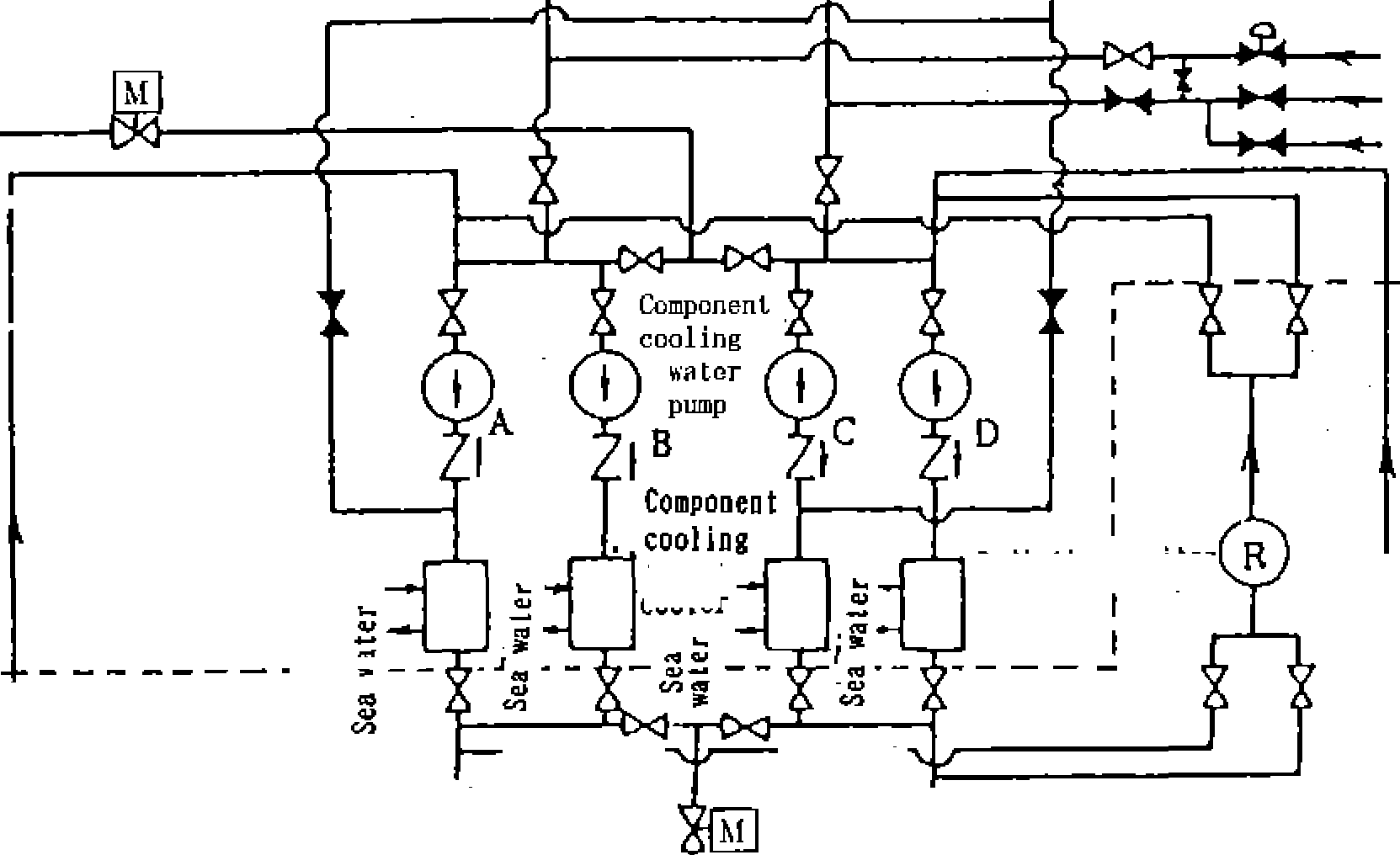
![]()
Instrument air compressor a
![]()
![]()
![]()
![]()
![]()
![]()
![]()
![]()
Instrument air cos pressor b
![]()
![]()
![]()
![]()
![]()
![]()
![]()
I .Aurillary components,
I [important for safetyj
