Isolation
amplifier
l
l I
Pressure
control
Protection
Protection channel 3 channel 4
I
r_L
• Pressure
’
■ control
J
7
Pressurizer
spray
relief
Low
pressure reactor trip
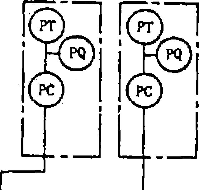
PT
: Pressure transmitter PQ
:
Power source
PC
:
Alarm set
ISOL
: Isolation amplifier
:
Protection system
:
Control system
valve
control
protection system performance requirement.
Hie reactor control system
is provided to control reactor power during design load changes and
power disturbances as well as to prevent expansion of the abnormal
behavior. In addition, the
reactor control system interlocks the actuation signals of the
control rod withdrawal blockage, the main feedwater valve isolation
system and other similar systems, before the reactor reaches the
trip condition. Based on the “centralized control philosophy",
control of the reactor system, as a matter of course, together with
the control of the turbine generator system, both are conducted from
the main control room. Following a turbine load change, the reactor
output is controlled to match it. The plant output control during
the normal plant operation is accomplished by regulating the steam
flow into the turbine system followed by reactivity regulation.
Reactivity control is
achieved by the combination of two independent methods, i.e., by
adjusting both the position of the control rod clusters (RCC) and
the concentration of boron in the reactor coolant
Control rods are mainly used to provide reactivity control for rapid
reactivity changes due to changes in plant output, coolant
temperature and other plant operation conditions as well as to
absorb excess reactivity during hot shutdown condition. On the
other hand, the boron concentration in the coolant is adjusted to
compensate for relatively slow reactivity changes, such as
reactivity changes due to fuel burnup and reactivity changes
associated with the amount of FP poisons, as well as to absorb
excess reactivity during the cold shutdown condition.
Below 15% of the rated power, the reactor power is manually
controlled by moving control rod clusters (RCC) in or out. Above 15%
of the rated power, the reactor power is automatically controlled.
The reactor control system enables the reactor to accept a ramp load
change of ±5% per minute and a step load change of ±10% within the
automatic control range (from 15% to 100% of the rated power).
Furthermore, the function of the turbine bypass control system
permits the plant to accept a 50% or 95% step load reduction without
reactor trip.
The reactor control system utilizes analog (or digital) controllers
and it consists of the following subsystems:
(D Control rod control
system;
Boron concentration control system;
Pressurizer pressure control system;
Pressurizer level control system;
Feedwater control system;
Turbine bypass control system;
Main steam relief valve control system; and
Control rod withdrawal prevention and turbine runback system.
NSRA,
Japan
3-70![]()

2/4 Logic
Figure 3.6.6 Pressurizer pressure protection and control system
Reactor control system
Chapter
3 Systems of PWR Nuclear Power Plants
A summary of the functional capabilities of these systems is
given in Table 3.6.6 and their block diagrams are shown in
Figures 3.6.7 through 3.6.12.
Control rod driving
mechanism
Control rod clusters (RCC: rod cluster control) are driven by the
magnetic jack-type control rod drive mechanisms (CRDMs)
attached to the top of the reactor vessel. Each CRCM
consists of the pressure housing, coil assembly, latch assembly,
and drive shaft assembly, etc. The coil assembly itself consists
of three independent magnetic coils surrounding the pressure
housing. The latch assembly is located within the pressure
housing and consists of latches, plungers, etc. The latches are
engaged with the grooved section of the drive shaft and lift or
lower the shaft step-by-step by moving up and down.
Large numbers of control rod clusters are provided in a PWR. They
are divided into the
shutdown group and control group, depending on their function.
Control rods of the control group are used during the normal
power operation, and those of the shutdown group (together with
the rods of the control group) are used to provide the necessary
shutdown reactivity. The control rod clusters are driven by
predetermined sequential excitation of the above mentioned coil
assemblies. Further, the driving direction (withdrawal or
insertion) and the driving speed of the control rod clusters are
controlled by the signals derived from the control rod control
system. The rates of either withdrawal or insertion of the
control rod clusters are proportional to the deviation signals
received from the control rod control system. The
control rod clusters can be withdrawn or inserted at a rate of up
to 114/min. Two full capacity parallel connected motor generator
sets, each receiving power from a separate 440 V bus, provide
power to the CRDMs. Furthermore, a flywheel is installed on each
motor to increase the rotating inertia thereby minimizing
Table
3.6.6 Functions of reactor control subsystems |
Functions |
Control Rod Control System |
Here, a control signal is generated by comparing reactor coolant average temperature with programmed reference temperature generated in proportion to turbine load, and the control signal, added to rate signals of turbine load and neutron flux, regulates speed of control rod cluster motion to maintain reactor coolant average temperature within predetermined values. |
Boric Acid Concentration Control System |
This system regulates relatively slow reactivity changes due to changes in fuel temperature, and xenon and samarium concentrations; and changes due to reactor coolant temperature change from low to high zero power condition. |
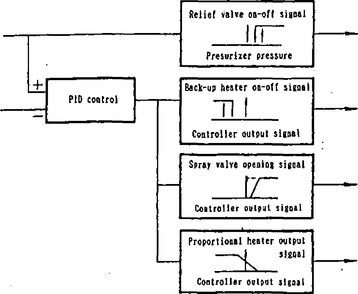
Pressurizer Pressure Control System |
Primary coolant pressure during transients is controlled by this system and the pressurizer so that the reactor pressure is maintained at constant pressure by spray, relief valves and heaters. |
Pressurizer Water Level Control System |
The pressurizer water level program is set proportionally to the reactor coolant average temperature so that it conforms to changes in reactor coolant water inventory due to power changes. From the difference signal between the pressurizer water level and the program level, charging flow from chemical and volume control system is automatically regulated. |
Feedwater Control System |
The feedwater control system of steam generators is provided for each steam generator to maintain the water level at the target level by controlling opening of the main feedwater control valve. The control system adopts three-element control by steam flow, feedwater flow and steam generator water level. |
Turbine Bypass Control System |
The turbine bypass control system dumps steam from steam generators directly into the steam condenser bypassing the turbine. The capacity is generally about 40 % of the rated steam flow. |
Main Steam Relief Valve Control System |
The main steam relief valve control system releases steam to the atmosphere by the steam relief valves. Tie capacity is about 10% of rated steam flow. |
Rod Withdrawal Block and Turbine Runback Control System |
to the system prevents abnormal events from expanding and takes automatic measures before reactor trip occurs by automatic manual blocking control rod withdrawal and turbine runback. |
3-77
NSRA,
Japan
NSRA,
Japan
G
Steam
regulating valve control signal
Spray
valve |
Pressure |
|
control system |
|
|
r L_. |
|
|
Pressurizer
Waler
level
RCC
control
system
L
Turbine
output
Primary
coolant average temp.
Main
steam
■relief
valve
'
Turbine
bypass valve
Heater
Condenser
To
other loop
coolant
pump
Boric
acid water
Primary
make-up water
Primary
coolant
pump
Ctiargi
ng/hi
gh pressure
injection
pump
Steam
reaulatingi
valve
<
|Main
feedwater
control
valve
Generator
Turbine
Pressurizer water
level
control system
Feedwater
control
system
I
Boric
acid mixer 1 |
1 t |
Boric acid concentration control system |
1 |
|
Turbine bypass
control
system
Main
feedwater pump
.speed
control signal
Reactor Output and turbine
output are added in the recent plants.
Three elements control with
addition of charging flow rate and letdown flow rate is adopted in
some plants.
Figure
3.6.7 Reactor control system

Chapter
3 Systems of PWR Nuclear Power Plants
A
- D depending on rnaber
of loops
Figure
3.6.8 Control rod control system
Pressurizer
pressure
Pressure
set point Ccoostant)
freI
Pressurizer
relief valve
Pressurizer
back-up healer
Pressurizer
sprat
Pressurizer
proportional heater
Figure
3.6.9 Pressurizer pressure control system
JiS
Three elements control with addition of letdown flow rate is adopted
in some plants.
Figure
3.6.10 Pressurizer water
level control
3-73
NSRA,
Japan