

signal by combining the individual signals obtained from the upper
section and the lower section neutron detectors, to monitor the
average core neutron flux level. If the neutron flux level or its
rate of change becomes higher than the specified value, each
instrumentation channel
sends a reactor trip signal to the reactor protection system to shut
down the reactor. The average signals from power instrumentation
channels are also used as the control signals for the control rod
control system. Furthermore, the core axial power distribution is
also monitored by observing the difference between the signals
obtained from the upper section and the lower section neutron
detectors. The core horizontal power distribution is monitored by
comparison between the average signal of each of the four power
instrumentation channels and each of the upper section or the lower
section signals.
In-core neutron instrumentation
The in-core neutron instrumentation system is provided for measuring
the neutron flux distribution through the movable miniature neutron
flux detectors (fission chambers) which are inserted into the center
of the fuel assemblies in the core as required. Measured values by
the in-core neutron flux detectors are used for calibration of the
out-of- core axial and horizontal neutron flux distribution
measurements, and are also used as input data for fuel and core
management
As shown in Figure 3.6.2, the in-core neutron instrumentation system
consists of the miniature neutron detectors, the detector drive
units and the core path selectors (used to route a detector into any
one of the flux thimbles at various selected core locations).
[Note] In-core instrumentation = In-core neutron instrumentation +
In-core thermal(temperature) instrumentation. Thermal (Temperature)
instrumentation is not usually included in Nuclear
10
3
t5x10-3
10
2
10
a
cS
10
o
£
a
$
10“3T
Intermediate
Range a
Trip
Point
IO’4
■ 10
5
102
■io-4
Power
Range Trip Point (Height Setting)
Power
Range Trip
Point
(Low Setting)
10-5
10“'
■IO'6
fe-’lO'"
g
I
10“2
10'7
IO-7
10“3
10“4
10~5--
i
a
£
•I
10“6
10~7--
10“8
I
10-9..
T106
■ ■10
4
103
--102
*
10°
10 s
10 9
10'10
101L
lO-io.
NSRA,
Japan
3-60
10 5 Neutron Source Range Trip Point
Figure 3.6.1 Out-of-core nuclear instrumentation range of measurement
Chapter
3 Systems of PWR Nuclear Power Plants
instrumentation.
In-core thermal instrumentation
The in-core temperature instrumentation system monitors core power
distribution by measuring the primary coolant temperature at the
fuel assembly outlet by using an alumelchromel thermocouple
installed in the upper core support structure and provides backup
data for the out-of-core nuclear instrumentation and the in-core
neutron instrumentation system. The data thus obtained are monitored
and analyzed by computer.
Control rod position indication system
The control rod position indication system is provided to indicate
the position of each control rod in the core. In each rod cluster
control (RCC), a total of 42 electrical coils are placed above the
control rod drive mechanism (CRDM)
external to the pressure housing and are used as the rod position
detectors. A digital signal proportional
to the rod position is provided by these detectors and displayed on
the main control panel.
In addition, about 4 to 9 RCC assemblies are grouped to be driven or
automatically controlled together as a bank. The RCC banks are
divided into the control groups which are used during the normal
power operation and the shutdown groups which are used together with
the control groups during the reactor shutdown. A deviation alarm is
actuated if any mismatching appears between the control rods of a
bank.
Furthermore, the bank position indicator associated with the control
rod control system, counts the driving steps of the RCC assemblies
of both the control and the shutdown groups. The bank position
signal is fed to the shutdown margin monitoring system.
(2) Safety protection
system
The safety protection
system consists of both the
Therso-ccyple
position
Fuel
assembly
Lover
core support coluin
In-core
instruaentation
guide
tube
Seactor
vessel adaptor
Figure
3.6.2 In & Out-of core nuclear instrumentation
3-61
NSRA,
Japan

reactor protection system and the engineered safety features (ESFs)
actuation system
a. Reactor protection system
i) Structure of the reactor
protection system
The reactor protection system provides safe reactor shutdown by
rapid insertion of RCCs into the core upon receiving a reactor trip
signal, and therefore, prevents loss of integrity of the nuclear
fuel and the reactor coolant pressure boundary under abnormal
transient conditions or, when an accident occurs during the plant
operation.
As shown in Figure 3.6.3, the reactor protection system consists of
a four-channel (or three- channel) analog circuit portion, a
two-train (or four-train) logic circuit portion and two (or four)
trip breakers, to provide a reliable system of sufficient redundancy
and independence. The analog circuit processes the signals received
from various detectors, and if they reach the preset values,
originates a bistable trip signal. The logic circuits receive and
combine separate trip signals from the analog circuit channels and
accomplish two-out-of-four (or two-out-of-three) logic calculation.
If two or more analog channels originate the trip signals, the
reactor trip signals are fed to the reactor
trip breakers. Power from motor generator sets (M-G
sets) is transmitted to the CRDMs through two series-connected trip
breakers RTA and RTB, in a two-train protection system, and, through
four reactor trip breakers (RTA, RTB, RTC and RTD) with a
two-out-of-four coincident logic matrix, in a four-train protection
system. The reactor trip breakers are normally closed which allows
the magnetic jacks of the CRDMs to get power from the M-G sets and
hold RCCs in a proper position above the core. Reactor trip signals
from each logic train de-energize the under-voltage coil on the
corresponding reactor trip breaker by disconnecting a direct current
circuit. Loss of the direct current source of the under-voltage coil
causes the reactor hip
breaker to open. Opening of the trip breaker interrupts power to the
CRDMs permitting the control rod cluster assemblies to free fall
into the core which results in the reactor shutdown. Opening of
either one of the two breakers in a two-train reactor protection
system (by a functional signal derived from either one of the two
logic trains), and either
two or more breakers out of the four breakers in a four-train
reactor protection system (by functional signals derived from either
two or more logic trains) will result in reactor trip. A block
diagram of the reactor protection system functions is given in
Figure 3.6.4.
The conventional analog and logic circuits of the safety protection
systems are nowadays being replaced by digital control systems using
microprocessors for new plants and the conventional systems in
operating plants are being replaced step-by-step.
ii) Reactor trip signals
and their functions
Various reactor trip
signals, together with the related logic network and
instrumentation channels are shown in Figure 3.6.4 and Table 3.6.1.
Permissive logic circuits are provided to block unnecessary reactor
trip signals during reactor operating conditions which ensure the
reactor continue to operate without compromising the reactor
protection system function. The permissive
signals are listed in Table 3.6.2. Also, the reactor trip
signals and their functions are listed in Table
3.6.3. The trip preset values are determined by analyzing the core
limits and considering sufficient room for safety margins and
instrumentation errors.
b. Engineered safety features actuation system i) Structure
of the engineered safety features
(ESFs) actuation system
The ESFs actuation system is provided to detect abnormal phenomena
during serious accidents such as the LOCA and the main steam piping
rupture, and to swiftly initiate operation of the related ESFs
system to prevent or mitigate extensive failure of nuclear fuel and
subsequent release of radioactive materials to ensure safety of the
general public as well as the station personnel.
The ESFs actuation system, similar to the reactor protection system
(Figure 3.6.3), consists of a four-channel (or three-channel) analog
circuit portion and a two-train (or four-train) logic circuit
portion to provide a reliable system of sufficient redundancy and
independence. The output signals of the logic circuit portion
actuate the operation of various ESFs equipment. A block diagram of
the ESFs actuation system functions is shown in Figure 3.6.5. The
actuating signals of
NSRA,
Japan
3-62
Chapter
3 Systems of PWR
Nuclear
Power Plants
Power
sou
re
Switchgear
train
A |
Engineered
safety feature;;
actuation
system con?»nents
(Train A)
Logic
train
AC
Source
AC
Source
Con
tai
went vessel
Process
detector, Transvit ter Containment
vessel penetration
A
Logic train B Logic train Reactor trip circuit breaker
AC
instrumentation
rack
Channel
Bistable
circuit
Reactor
instruoentation
or
Process
instrumentation of
protection systea
Reactor
protection systea
Power
source |
|
4§) r"n |
H«I |
r”~i |
|||
[2^Sfc^ircui t J |
|||||||
4E r"n |
i *4EI n |
r"“l |
45) r*i |
||||
logic circuit.j |
|||||||
uv
[yv
UV:
Unstable voltage
coil
RT: Reactor trip circuit
breaker
R-G
set for control rod
drive ■echanlsa
Reactor
trip bypass circuit breaker
(a)
2 train system
Logic
train B
Process
detector, Transaltter
AC
Source
Bistable
circuit
train
B
c
Logic
train
Logic
’/
train D1.’
Containvent
vessel penetration
Containaent
vessel
Instrumentation
rack
'
Channel
train
B
train C
\train
B strain B
strain
C K
train C
Power
source
( [ i r-—1 1
Control
rad .Control
rod Switchgear_
Power control
unit drive at
chan1sb
train B j
sour?
I
Logic circuit C J
Engineered
safety features actuation
system components
(Train
B)
Reactor
instrumentation or Process instruaentation of protection systea
Reactor
protection systea
Source
Source
for RCC
Source
Logic
circuit D I
T
train
B
control
rad
control unit
train
AJ
Engineered
safety features actuation system components
(Train
B)
UV:
Unstable voltage coil RT:
Reactor trip circuit breaker
RCC
driving aechanisa
Engineered
safely features actuation system components
(Train
A)
(b)
4 train system
Figure
3.6.3 Reactor protection and engineered safety features actuation
system
3-63
NSRA,
Japan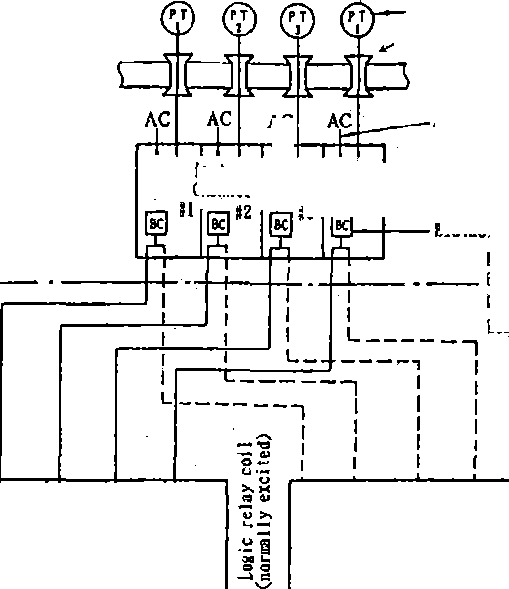


![]()

![]()
MdfoAteto,
g,![]()
Table
3.6.1 List of reactor trip signals |
Detector |
Actuation Logic |
Interlock |
High Neutron Source Range Neutron Flux |
Neutron Source Range Neutron Flux Detector |
1/2 |
Manual Block above (P-6) Automatic Block above (P-10) |
High Intermediate Range Neutron Flux . |
Intermediate Range Neutron Flux Detector |
1/2 |
Manual Block above (P-10) |
High Power Range Neutron Flux
|
Power Range Neutron Flux Detector Power Range Neutron Flux Detector |
2/4 2/4 |
Manual Block above (P-10) for Low Setting |
High Power Range Neutron Flux Change Rate
|
Power Range Neutron Flux Detector Power Range Neutron Flux Detector |
2/4 2/4 |
|
Emergency Core Cooling System (ECIS) Actuation |
|
|
Refer to Table 3. 6.4 |
Over Temperature AT |
Reactor Coolant Temperature Detector Pressurizer Pressure Detector Power Range Neutron Flux Detector (upper and lower) |
2/4 |
|
Over Power AT |
Reactor Coolant Temperature Detector Power Range Neutron Flux Detector |
2/4 |
|
High Reactor Pressure |
Pressurizer Puressure Detector |
2/4 |
|
Low Reactor Pressure |
Pressurizer Puressure Detector |
2/4 |
Automatic Block below (P-7) |
Low Reactor Coolant Flow Rate |
Reactor Coolant Flow Rate Detector |
2/3 for Each Loop (Note 2) |
Automatic Block below (P-8) for 1 Loop. Automatic Block above (P-7) for 2 or more than 2 Loops |
Low Reactor Coolant Pump Power Voltage |
Reactor Coolant PumpLow Voltage Relay |
In coincidence of 2 or more 2/3 for Each Power Source |
Automatic Block below (P-7) |
Low Reactor Coolant Pump Power Frequency |
Reactor Coolant Pump Frequency Relay |
In coincidence of 2 or more 2/3 for Each Power Source |
Automatic Block below (P-7) |
Turbine Trip |
Turbine Emergency ShutdownOil Pressure DetectorMain Steam Stop Valve |
2/3 (Note2) Loop Close 4 Sets |
Automatic Block below (P-7) |
Low Steam Generator Water Level (Note 1) |
Steam Generator water Level Detector |
2/4 for Each Steam Generator |
|
Low Steam Generator Feed Water Flow Rate (Note 1) |
Main Steam Flow Detector Feadwater Flow Detector Steam Generator later Level Detector |
Coincidence of 1/2 of Deviation between Main Steam and Feed Water Flow High and 1/2 of Steam Generator Level Low |
|
High Pressurizer later Level |
Pressurizer later Level Detector |
2/4 |
Automatic Block below (P-7) |
High Seismic Acceleration
|
Horizontal Acceleration Detector Vertical Acceleration Detector |
2/3 2/3 |
|
Manual |
|
1/2 |
|
^Note
1] Only Steam Generator water Level Low Signal in adopted in recent
plants. [Note 2] 2/4
instead of 2/3 in recent plants.
NSRA,
Japan
3-64
Chapter
3 Systems of PWR Nuclear Power Plants
Table
3.6.2 List of permissive signals for reactor trip signals Signals |
Function |
Input Signals |
P-6 |
Permission of manual block for reactor trip due to high neutron source range neutron flux trip |
1/2 of high intermediate range neutron flux value |
P-7 |
|
2/4 of high power range neutron flux value or 1/2 of high pressure value after 1st. stage turbine |
P-8 |
Permission for reactor trip due to signal of low reactor coolant flow rate in one loop |
2/4 of high power range neutron flux value |
P-10 |
|
2/4 of high power range neutron flux value |
[Note]
2/4 in the recent plants
3-65
NSRA,
Japan