


2.4. BASIC GL OPERATION |
10 |
Display
List
|
|
|
|
|
|
|
|
|
|
|
|
|
|
|
|
Per−Vertex |
|
|
|
|
|
Per− |
|
|
|
Evaluator |
|
|
Operations |
|
|
Rasteriz− |
|
|
|
|
|
|
|
|
|
|
|
|
|
Fragment |
|
|
Framebuffer |
||
|
|
Primitive |
|
|
ation |
|
|
|
|
|||
|
|
|
|
|
|
|
Operations |
|
|
|
||
|
|
|
Assembly |
|
|
|
|
|
|
|
|
|
|
|
|
|
|
|
|
|
|
|
|
|
|
|
|
|
|
|
|
|
|
|
|
|
|
|
Texture
Memory
Pixel
Operations
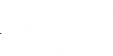
Figure 2.1. Block diagram of the GL.
2.4Basic GL Operation
Figure 2.1 shows a schematic diagram of the GL. Commands enter the GL on the left. Some commands specify geometric objects to be drawn while others control how the objects are handled by the various stages. Most commands may be accumulated in a display list for processing by the GL at a later time. Otherwise, commands are effectively sent through a processing pipeline.
The first stage provides an efficient means for approximating curve and surface geometry by evaluating polynomial functions of input values. The next stage operates on geometric primitives described by vertices: points, line segments, and polygons. In this stage vertices are transformed and lit, and primitives are clipped to a viewing volume in preparation for the next stage, rasterization. The rasterizer produces a series of framebuffer addresses and values using a two-dimensional description of a point, line segment, or polygon. Each fragment so produced is fed to the next stage that performs operations on individual fragments before they fi- nally alter the framebuffer. These operations include conditional updates into the framebuffer based on incoming and previously stored depth values (to effect depth buffering), blending of incoming fragment colors with stored colors, as well as masking and other logical operations on fragment values.
Finally, there is a way to bypass the vertex processing portion of the pipeline to send a block of fragments directly to the individual fragment operations, eventually causing a block of pixels to be written to the framebuffer; values may also be read
Version 2.0 - October 22, 2004
2.5. GL ERRORS |
11 |
back from the framebuffer or copied from one portion of the framebuffer to another. These transfers may include some type of decoding or encoding.
This ordering is meant only as a tool for describing the GL, not as a strict rule of how the GL is implemented, and we present it only as a means to organize the various operations of the GL. Objects such as curved surfaces, for instance, may be transformed before they are converted to polygons.
2.5GL Errors
The GL detects only a subset of those conditions that could be considered errors. This is because in many cases error checking would adversely impact the performance of an error-free program.
The command
enum GetError( void );
is used to obtain error information. Each detectable error is assigned a numeric code. When an error is detected, a flag is set and the code is recorded. Further errors, if they occur, do not affect this recorded code. When GetError is called, the code is returned and the flag is cleared, so that a further error will again record its code. If a call to GetError returns NO ERROR, then there has been no detectable error since the last call to GetError (or since the GL was initialized).
To allow for distributed implementations, there may be several flag-code pairs. In this case, after a call to GetError returns a value other than NO ERROR each subsequent call returns the non-zero code of a distinct flag-code pair (in unspecified order), until all non-NO ERROR codes have been returned. When there are no more non-NO ERROR error codes, all flags are reset. This scheme requires some positive number of pairs of a flag bit and an integer. The initial state of all flags is cleared and the initial value of all codes is NO ERROR.
Table 2.3 summarizes GL errors. Currently, when an error flag is set, results of GL operation are undefined only if OUT OF MEMORY has occurred. In other cases, the command generating the error is ignored so that it has no effect on GL state or framebuffer contents. If the generating command returns a value, it returns zero. If the generating command modifies values through a pointer argument, no change is made to these values. These error semantics apply only to GL errors, not to system errors such as memory access errors. This behavior is the current behavior; the action of the GL in the presence of errors is subject to change.
Several error generation conditions are implicit in the description of every GL command:
Version 2.0 - October 22, 2004