

- •0.1 APPROVAL
- •0.2 RECORD OF REVISIONS
- •0.3 LIST OF EFFECTIVE PAGES
- •0.4 TABLE OF CONTENTS
- •1 GENERAL
- •1.1 INTRODUCTION
- •1.2 CERTIFICATION BASIS
- •1.3 WARNINGS, CAUTIONS AND NOTES
- •1.4 DIMENSIONS
- •1.5 DEFINITIONS AND ABBREVIATIONS
- •1.6 UNITS OF MEASUREMENT
- •1.6.1 CONVERSION FACTORS
- •1.7 THREE-VIEW DRAWING
- •1.8 SOURCE DOCUMENTATION
- •1.8.1 ENGINE AND ENGINE INSTRUMENTS
- •1.8.2 PROPELLER
- •2 OPERATING LIMITATIONS
- •2.1 INTRODUCTION
- •2.2 AIRSPEED
- •2.3 AIRSPEED INDICATOR MARKINGS
- •2.4 POWER-PLANT LIMITATIONS
- •2.5 ENGINE INSTRUMENT MARKINGS
- •2.6 WARNING, CAUTION AND STATUS LIGHTS
- •2.7 MASS (WEIGHT)
- •2.8 CENTER OF GRAVITY
- •2.9 APPROVED MANEUVERS
- •2.10 MANEUVERING LOAD FACTORS
- •2.11 OPERATING ALTITUDE
- •2.12 FLIGHT CREW
- •2.13 KINDS OF OPERATION
- •2.14 FUEL
- •2.15 LIMITATION PLACARDS
- •2.16 OTHER LIMITATIONS
- •2.16.1 TEMPERATURE
- •2.16.2 BATTERY CHARGE
- •2.16.3 EMERGENCY SWITCH
- •2.16.4 DOOR LOCKING DEVICE
- •2.16.5 ELECTRONIC EQUIPMENT
- •2.16.6 SMOKING
- •2.16.7 USE OF THE SUN VISORS
- •3 EMERGENCY PROCEDURES
- •3.1 INTRODUCTION
- •3.1.1 GENERAL
- •3.1.2 CERTAIN AIRSPEEDS IN EMERGENCIES
- •3.2 INSTRUMENT INDICATIONS IN PROHIBITED (RED) RANGE
- •3.2.1 ENGINE TEMPERATURE
- •3.2.2 OIL TEMPERATURE
- •3.2.3 OIL PRESSURE
- •3.2.4 GEARBOX TEMPERATURE
- •3.2.5 L/R FUEL TEMPERATURE
- •3.2.6 FUEL PRESSURE
- •3.2.7 ALTERNATOR AMPS
- •3.2.8 ALTERNATOR FAIL
- •3.3 ENGINE PROBLEMS
- •3.3.1 ENGINE PROBLEMS ON GROUND
- •3.3.2 ENGINE PROBLEMS DURING TAKE-OFF
- •3.3.3 ENGINE TROUBLESHOOTING IN FLIGHT
- •3.3.4 ENGINE FAILURE IN FLIGHT
- •3.3.5 RESTARTING THE ENGINE IN FLIGHT
- •3.3.6 DEFECTIVE RPM REGULATING SYSTEM
- •3.3.7 FUEL TRANSFER PUMP FAILURE
- •3.4 FAILURES IN THE ELECTRICAL SYSTEM
- •3.4.1 COMPLETE FAILURE OF THE ELECTRICAL SYSTEM
- •3.4.2 HIGH CURRENT
- •3.4.3 STARTER MALFUNCTION
- •3.5 SMOKE AND FIRE
- •3.5.1 SMOKE AND FIRE ON GROUND
- •3.5.2 SMOKE AND FIRE DURING TAKE-OFF
- •3.5.3 SMOKE AND FIRE IN FLIGHT
- •3.7 EMERGENCY LANDINGS
- •3.7.1 EMERGENCY LANDING WITH ENGINE OFF
- •3.7.2 LANDING WITH A DEFECTIVE TIRE ON THE MAIN LANDING GEAR
- •3.7.3 LANDING WITH DEFECTIVE BRAKES
- •3.8 RECOVERY FROM AN UNINTENTIONAL SPIN
- •3.9 OTHER EMERGENCIES
- •3.9.1 ICING
- •3.9.2 SUSPICION OF CARBON MONOXIDE CONTAMINATION IN THE CABIN
- •3.9.3 UNLOCKED DOORS
- •4A NORMAL OPERATING PROCEDURES
- •4A.1 INTRODUCTION
- •4A.2 AIRSPEEDS FOR NORMAL OPERATING PROCEDURES
- •4A.3 FLIGHT CHARACTERISTICS
- •4A.4 DAILY CHECK
- •4A.5 CHECKLISTS FOR NORMAL OPERATING PROCEDURES
- •4A.5.1 PRE-FLIGHT INSPECTION
- •4A.5.2 BEFORE STARTING ENGINE
- •4A.5.3 STARTING ENGINE
- •4A.5.4 BEFORE TAXIING
- •4A.5.5 TAXIING
- •4A.5.6 BEFORE TAKE-OFF
- •4A.5.7 TAKE-OFF
- •4A.5.8 CLIMB
- •4A.5.9 CRUISE
- •4A.5.10 FUEL TRANSFER
- •4A.5.11 DESCENT
- •4A.5.12 APPROACH & LANDING
- •4A.5.13 GO-AROUND
- •4A.5.14 AFTER LANDING
- •4A.5.15 ENGINE SHUT-DOWN
- •4A.5.16 POST FLIGHT INSPECTION
- •4A.5.17 PARKING
- •4A.5.18 FLIGHT IN RAIN
- •4A.5.19 REFUELING
- •4A.5.20 FLIGHT AT HIGH ALTITUDE
- •4B ABNORMAL OPERATING PROCEDURES
- •4B.1 PRECAUTIONARY LANDING
- •4B.2 INSTRUMENT INDICATIONS OUTSIDE OF GREEN RANGE
- •4B.2.2 COOLANT TEMPERATURE
- •4B.2.3 OIL TEMPERATURE
- •4B.2.4 OIL PRESSURE
- •4B.2.5 GEARBOX TEMPERATURE
- •4B.2.6 FUEL TEMPERATURE
- •4B.2.7 VOLTAGE
- •4B.2.8 CURRENT
- •4B.3 CAUTION-ALERTS
- •4B.3.1 ECU A FAILURE
- •4B.3.2 ECU B FAILURE
- •4B.3.3 FUEL QUANTITY LOW
- •4B.3.4 COOLANT LEVEL
- •4B.3.5 PITOT HEATING FAILURE
- •4B.3.6 ENGINE CAUTION (IF WHITE WIRE ANNUNCIATOR PANEL IS INSTALLED)
- •4B.4 CANOPY IN COOLING GAP POSITION
- •4B.5 FAILURES IN FLAP OPERATING SYSTEM
- •4B.6 LIGHTNING STRIKE
- •4B.7 LANDING WITH MASS ABOVE MAXIMUM LANDING MASS
- •4B.8 STARTING ENGINE WITH EXTERNAL POWER
- •4B.8.1 BEFORE STARTING ENGINE
- •4B.8.2 STARTING ENGINE
- •5 PERFORMANCE
- •5.1 INTRODUCTION
- •5.2 USE OF THE PERFORMANCE TABLES AND DIAGRAMS
- •5.3 PERFORMANCE TABLES AND DIAGRAMS
- •5.3.1 AIRSPEED CALIBRATION
- •5.3.2 FUEL FLOW
- •5.3.3 PRESSURE ALTITUDE - DENSITY ALTITUDE
- •5.3.4 INTERNATIONAL STANDARD ATMOSPHERE
- •5.3.5 STALLING SPEEDS
- •5.3.6 WIND COMPONENTS
- •5.3.7 TAKE-OFF DISTANCE
- •5.3.8 CLIMB PERFORMANCE - TAKE-OFF CLIMB
- •5.3.9 CLIMB PERFORMANCE - CRUISE CLIMB
- •5.3.10 TIME, FUEL AND DISTANCE TO CLIMB
- •5.3.11 CRUISE PERFORMANCE
- •5.3.12 LANDING DISTANCES
- •5.3.14 GO-AROUND CLIMB PERFORMANCE
- •5.3.15 GLIDE
- •5.3.16 APPROVED NOISE DATA
- •6 MASS AND BALANCE / EQUIPMENT LIST
- •6.1 INTRODUCTION
- •6.2 DATUM PLANE
- •6.3 MASS AND BALANCE REPORT
- •6.4 FLIGHT MASS AND CENTER OF GRAVITY
- •6.4.1 MOMENT ARMS
- •6.4.2 LOADING DIAGRAM
- •6.4.3 CALCULATION OF LOADING CONDITION
- •6.4.4 PERMISSIBLE CENTER OF GRAVITY RANGE
- •6.4.5 PERMISSIBLE MOMENT RANGE
- •6.5 EQUIPMENT LIST AND EQUIPMENT INVENTORY
- •7.1 INTRODUCTION
- •7.2 AIRFRAME
- •7.3 FLIGHT CONTROLS
- •7.4 INSTRUMENT PANEL
- •7.5 LANDING GEAR
- •7.6 SEATS AND SAFETY HARNESSES
- •7.7 BAGGAGE COMPARTMENT
- •7.8 CANOPY, REAR DOOR, AND CABIN INTERIOR
- •7.9.1 ENGINE, GENERAL
- •7.9.2 OPERATING CONTROLS
- •7.9.3 PROPELLER
- •7.9.4 FUEL SYSTEM
- •7.9.5 COOLING SYSTEM
- •7.9.7 OIL SYSTEMS
- •7.10.1 GENERAL
- •7.10.2 ENGINE CONTROL UNIT / ECU
- •7.11 PITOT-STATIC SYSTEM
- •7.12 STALL WARNING SYSTEM
- •8 AIRPLANE HANDLING, CARE AND MAINTENANCE
- •8.1 INTRODUCTION
- •8.2 AIRPLANE INSPECTION INTERVALS
- •8.4 GROUND HANDLING / ROAD TRANSPORT
- •8.4.1 GROUND HANDLING WITHOUT TOW BAR
- •8.4.2 GROUND HANDLING WITH TOW BAR
- •8.4.3 PARKING
- •8.4.4 MOORING
- •8.4.5 JACKING
- •8.4.6 ALIGNMENT
- •8.4.7 ROAD TRANSPORT
- •8.5 CLEANING AND CARE
- •8.5.1 PAINTED SURFACES
- •8.5.2 CANOPY AND REAR DOOR
- •8.5.3 PROPELLER
- •8.5.4 ENGINE
- •8.5.5 INTERIOR SURFACES
- •8.6 GROUND DE-ICING
- •9 SUPPLEMENTS
- •9.1 INTRODUCTION
- •9.2 LIST OF SUPPLEMENTS
DA 40 NG AFM
Airplane
Description
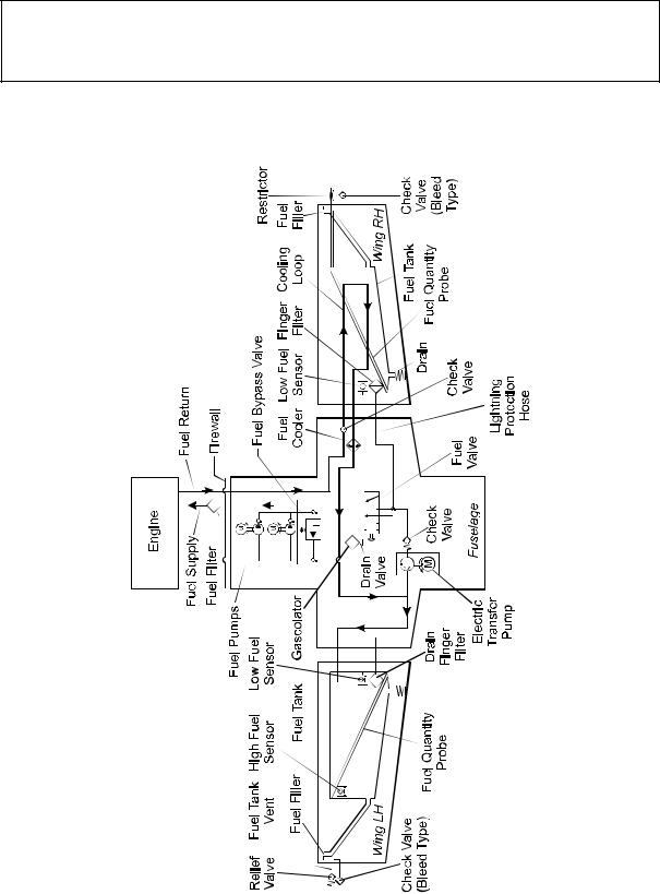
7.9.4 FUEL SYSTEM
Standard Tank Schematic
Doc. # 6.01.15-E |
Rev. 3 |
01-Jul-2014 |
Page 7 - 27 |
|
|
|
|
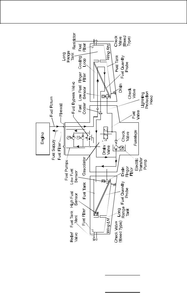
Airplane
DA 40 NG AFM
Description
Long Range Tank Schematic
Page 7 - 28 |
Rev. 3 |
01-Jul-2014 |
|
Doc. # 6.01.15-E |
|
|
|
|
|
DA 40 NG AFM
Airplane
Description
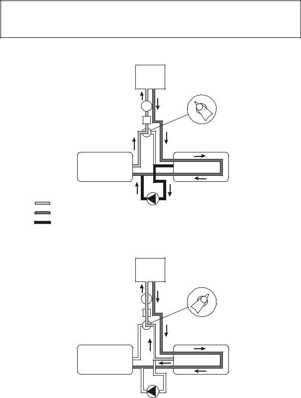
Normal Fuel Supply & |
Engine |
Fuel Valve |
|
Normal Fuel Transfer |
|
||
|
Normal |
|
|
|
|
Emergency |
|
Fuel Filter |
|
|
|
Fuel Pumps |
|
Off |
|
|
|
|
|
Main Tank |
|
Auxiliary Tank |
|
Fuel Supply |
Transfer Pump |
|
|
Fuel Return |
|
||
|
|
|
|
Fuel Transfer |
|
|
|
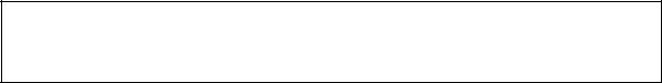
Emergency Fuel Supply & |
Engine |
Fuel Valve |
||
Emergency Fuel Transfer |
||||
|
||||
|
|
Normal |
Emergency |
|
Fuel Filter |
|
|
|
|
Fuel Pumps |
|
Off |
||
|
|
|
||
Main Tank |
|
Auxiliary Tank |
||
Transfer Pump

 Emergency Fuel Supply

 Emergency Fuel Return & Fuel Return
Doc. # 6.01.15-E |
Rev. 3 |
01-Jul-2014 |
Page 7 - 29 |
|
|
|
|

Airplane
DA 40 NG AFM
Description
Fuel is stored in the fuel tanks which are located in the wings. Normally fuel is taken from the MAIN tank (left wing).
The fuel is injected with high pressure directly into the combustion chambers. The injection nozzles (one per cylinder) are supplied with fuel by the common rail. Pressure inside the rail is generated by a high pressure pump which receives fuel from two independent low pressure fuel pumps. Both pumps are powered electrically. Depending on the power setting the rail pressure is controlled by the ECU through an electric valve.
Fuel that is not injected into the combustion chambers is routed through the AUX fuel tank (right wing) and fed back into the MAIN fuel tank (left wing). This way hot fuel from the rail is cooled and cold fuel in both tanks is heated.
With the help of an electrical transfer pump fuel can be transferred from the AUX tank
(right wing) to the MAIN tank (left wing) manually.
The transfer pump is switched off automatically when the auxiliary tank is empty or the main tank is full.
If fuel transfer with the transfer pump becomes impossible for any reason, fuel can also be taken directly from the AUX tank (right wing) by switching the fuel valve to the EMERGENCY position. As the return line goes back into the MAIN tank (left wing), fuel will then be transferred from right to left fuel tank.
As an option additional long range tanks may be installed.
Page 7 - 30 |
Rev. 3 |
01-Jul-2014 |
|
Doc. # 6.01.15-E |
|
|
|
|
|
DA 40 NG AFM
Airplane
Description
CAUTION
Switching the fuel valve to the EMERGENCY position will start the transferring of fuel with the help of the electrically driven and engine driven fuel pumps from the auxiliary tank through the fuel return line to the main tank at a rate of approximately
45 US gal/h (170 liter/h) with FUEL PUMPS switch in OFF position. The fuel valve must be switched back to the NORMAL position before the auxiliary tank indication reads zero. If the fuel valve is not switched back to the NORMAL position, the engine will stop running as soon as the auxiliary tank is empty.
Fuel Pumps
The engine is supplied with fuel by two parallel installed independent low pressure electrically driven fuel pumps. During normal operation one of the two fuel pumps is always working. In case of a low fuel pressure, the ECU switches automatically to the second fuel pump. During landing and take-off, or in case of a low fuel pressure both fuel pumps can be activated with the FUEL PUMPS switch. If both fuel pumps are are set to ON the fuel pressure increases.
Each fuel pump is electrically connected to an ECU BUS and protected by a 7.5 A circuit breaker.
NOTE
By switching between ECU A and B the two independent electrical fuel pumps are switched over as well. In case of an emergency both pumps can be activated simultaneously by pushing the FUEL PUMPS switch to the ON position.
Doc. # 6.01.15-E |
Rev. 3 |
01-Jul-2014 |
Page 7 - 31 |
|
|
|
|

Airplane
DA 40 NG AFM
Description
Fuel Valve
The fuel valve is located at the center console. The selectable positions are NORMAL, EMERGENCY and OFF. The desired position is reached by turning the valve handle while pulling up the safety latch on the valve handle. This is to ensure that a selection is not made unintentionally.
Standard Fuel Tanks
Main Tank (Left Wing):
The main tank consists of an aluminum chamber and a filler tube which are connected by a flexible hose. There are two tank vents. One includes a check valve with a capillary and one includes a pressure relief valve, which operates at 150 mbar (2 PSI) and allows fuel and air to flow to the outside at higher internal pressure. The relief pressure valve protects the tank against high pressure if the tank will be overfilled in case of a fuel transfer failure. The check valve with capillary allows air to enter the tank but prevents flow of fuel to the outside. The capillary equalizes the air pressure during climb. The hose terminations are situated on the underside of the wing, approximately 2 meter (7 ft) from the wing tip.
Auxiliary Tank (Right Wing):
The auxiliary tank consists of an aluminum chamber and a filler tube which are connected by a flexible hose. There are two tank vents. One includes a check valve with a capillary and one includes a capillary. The check valve with capillary allows air to enter the tank during descent but prevents flow of fuel to the outside. The capillary equalizes the air pressure during climb. The second capillary is installed for additional safety. The hose terminations are situated on the underside of the wing, approximately 2 meter (7 ft) from the wing tip.
In each tank a coarse filter (finger filter) is fitted before the outlet. To allow draining of the tank, an outlet valve (drain valve) is installed at the lowest point of the fuel tank.
Page 7 - 32 |
Rev. 3 |
01-Jul-2014 |
|
Doc. # 6.01.15-E |
|
|
|
|
|
DA 40 NG AFM
Airplane
Description
A gascolator is located at the bottom side of the fuselage which is the lowest point of the entire fuel system. A drain valve (pull to drain) is mounted to the gascolator, to allow the remove of water and sediment which has collected in the fuel system.
A capacity probe measures the fuel quantity in each tank. The indication is non-linear, therefore proportional calculations to determine the remaining fuel quantity or direct calculations of fuel consumption are not possible. Information about the fuel consumption can be found in Chapter 5 - PERFORMANCE.
Long Range Tank (if installed)
The tank chamber has a capacity of approx. 5 US gal (19 liter). The ventilation system of the main and the auxiliary tank remains unchanged.
When the fuel quantity indicator reads zero, only the unusable fuel remains in the tank.
The useable capacity of each tank is 19.5 US gal, the maximum quantity that can be indicated is 14 US gal. Up to an actual quantity of 14 US gal the indication is correct. At an actual quantity above 14 US gal the indication remains at 14 US gal.
NOTE
When the fuel quantity indicator reads 14 US gal, the correct fuel quantity must be determined with the alternate mean for fuel quantity indication. If this measurement is not carried out, the fuel quantity available for flight planning is 14 US gal.
Doc. # 6.01.15-E |
Rev. 3 |
01-Jul-2014 |
Page 7 - 33 |
|
|
|
|

Airplane
DA 40 NG AFM
Description
Alternate Means For Fuel Quantity Indication
The alternate means for fuel quantity indication allows the fuel quantity in the tank to be determined during the pre-flight inspection. It functions according to the principle of communicating containers. The fuel quantity measuring device has a recess which fits the airfoil of the wing. With this recess the device is held against the stall strip at the leading edge of the wing. The exact position is marked by a bore in the stall strip. Then the metal connector is pressed against the drain of the tank. The amount of fuel in the tank can now be read off from the vertical ascending pipe.
For an exact indication the airplane must stand on a horizontal ground.
The designated place for the fuel quantity measuring device is the bag on the rear side of the pilot seat.
Page 7 - 34 |
Rev. 3 |
01-Jul-2014 |
|
Doc. # 6.01.15-E |
|
|
|
|
|