

- •0.1 APPROVAL
- •0.2 RECORD OF REVISIONS
- •0.3 LIST OF EFFECTIVE PAGES
- •0.4 TABLE OF CONTENTS
- •1 GENERAL
- •1.1 INTRODUCTION
- •1.2 CERTIFICATION BASIS
- •1.3 WARNINGS, CAUTIONS AND NOTES
- •1.4 DIMENSIONS
- •1.5 DEFINITIONS AND ABBREVIATIONS
- •1.6 UNITS OF MEASUREMENT
- •1.6.1 CONVERSION FACTORS
- •1.7 THREE-VIEW DRAWING
- •1.8 SOURCE DOCUMENTATION
- •1.8.1 ENGINE AND ENGINE INSTRUMENTS
- •1.8.2 PROPELLER
- •2 OPERATING LIMITATIONS
- •2.1 INTRODUCTION
- •2.2 AIRSPEED
- •2.3 AIRSPEED INDICATOR MARKINGS
- •2.4 POWER-PLANT LIMITATIONS
- •2.5 ENGINE INSTRUMENT MARKINGS
- •2.6 WARNING, CAUTION AND STATUS LIGHTS
- •2.7 MASS (WEIGHT)
- •2.8 CENTER OF GRAVITY
- •2.9 APPROVED MANEUVERS
- •2.10 MANEUVERING LOAD FACTORS
- •2.11 OPERATING ALTITUDE
- •2.12 FLIGHT CREW
- •2.13 KINDS OF OPERATION
- •2.14 FUEL
- •2.15 LIMITATION PLACARDS
- •2.16 OTHER LIMITATIONS
- •2.16.1 TEMPERATURE
- •2.16.2 BATTERY CHARGE
- •2.16.3 EMERGENCY SWITCH
- •2.16.4 DOOR LOCKING DEVICE
- •2.16.5 ELECTRONIC EQUIPMENT
- •2.16.6 SMOKING
- •2.16.7 USE OF THE SUN VISORS
- •3 EMERGENCY PROCEDURES
- •3.1 INTRODUCTION
- •3.1.1 GENERAL
- •3.1.2 CERTAIN AIRSPEEDS IN EMERGENCIES
- •3.2 INSTRUMENT INDICATIONS IN PROHIBITED (RED) RANGE
- •3.2.1 ENGINE TEMPERATURE
- •3.2.2 OIL TEMPERATURE
- •3.2.3 OIL PRESSURE
- •3.2.4 GEARBOX TEMPERATURE
- •3.2.5 L/R FUEL TEMPERATURE
- •3.2.6 FUEL PRESSURE
- •3.2.7 ALTERNATOR AMPS
- •3.2.8 ALTERNATOR FAIL
- •3.3 ENGINE PROBLEMS
- •3.3.1 ENGINE PROBLEMS ON GROUND
- •3.3.2 ENGINE PROBLEMS DURING TAKE-OFF
- •3.3.3 ENGINE TROUBLESHOOTING IN FLIGHT
- •3.3.4 ENGINE FAILURE IN FLIGHT
- •3.3.5 RESTARTING THE ENGINE IN FLIGHT
- •3.3.6 DEFECTIVE RPM REGULATING SYSTEM
- •3.3.7 FUEL TRANSFER PUMP FAILURE
- •3.4 FAILURES IN THE ELECTRICAL SYSTEM
- •3.4.1 COMPLETE FAILURE OF THE ELECTRICAL SYSTEM
- •3.4.2 HIGH CURRENT
- •3.4.3 STARTER MALFUNCTION
- •3.5 SMOKE AND FIRE
- •3.5.1 SMOKE AND FIRE ON GROUND
- •3.5.2 SMOKE AND FIRE DURING TAKE-OFF
- •3.5.3 SMOKE AND FIRE IN FLIGHT
- •3.7 EMERGENCY LANDINGS
- •3.7.1 EMERGENCY LANDING WITH ENGINE OFF
- •3.7.2 LANDING WITH A DEFECTIVE TIRE ON THE MAIN LANDING GEAR
- •3.7.3 LANDING WITH DEFECTIVE BRAKES
- •3.8 RECOVERY FROM AN UNINTENTIONAL SPIN
- •3.9 OTHER EMERGENCIES
- •3.9.1 ICING
- •3.9.2 SUSPICION OF CARBON MONOXIDE CONTAMINATION IN THE CABIN
- •3.9.3 UNLOCKED DOORS
- •4A NORMAL OPERATING PROCEDURES
- •4A.1 INTRODUCTION
- •4A.2 AIRSPEEDS FOR NORMAL OPERATING PROCEDURES
- •4A.3 FLIGHT CHARACTERISTICS
- •4A.4 DAILY CHECK
- •4A.5 CHECKLISTS FOR NORMAL OPERATING PROCEDURES
- •4A.5.1 PRE-FLIGHT INSPECTION
- •4A.5.2 BEFORE STARTING ENGINE
- •4A.5.3 STARTING ENGINE
- •4A.5.4 BEFORE TAXIING
- •4A.5.5 TAXIING
- •4A.5.6 BEFORE TAKE-OFF
- •4A.5.7 TAKE-OFF
- •4A.5.8 CLIMB
- •4A.5.9 CRUISE
- •4A.5.10 FUEL TRANSFER
- •4A.5.11 DESCENT
- •4A.5.12 APPROACH & LANDING
- •4A.5.13 GO-AROUND
- •4A.5.14 AFTER LANDING
- •4A.5.15 ENGINE SHUT-DOWN
- •4A.5.16 POST FLIGHT INSPECTION
- •4A.5.17 PARKING
- •4A.5.18 FLIGHT IN RAIN
- •4A.5.19 REFUELING
- •4A.5.20 FLIGHT AT HIGH ALTITUDE
- •4B ABNORMAL OPERATING PROCEDURES
- •4B.1 PRECAUTIONARY LANDING
- •4B.2 INSTRUMENT INDICATIONS OUTSIDE OF GREEN RANGE
- •4B.2.2 COOLANT TEMPERATURE
- •4B.2.3 OIL TEMPERATURE
- •4B.2.4 OIL PRESSURE
- •4B.2.5 GEARBOX TEMPERATURE
- •4B.2.6 FUEL TEMPERATURE
- •4B.2.7 VOLTAGE
- •4B.2.8 CURRENT
- •4B.3 CAUTION-ALERTS
- •4B.3.1 ECU A FAILURE
- •4B.3.2 ECU B FAILURE
- •4B.3.3 FUEL QUANTITY LOW
- •4B.3.4 COOLANT LEVEL
- •4B.3.5 PITOT HEATING FAILURE
- •4B.3.6 ENGINE CAUTION (IF WHITE WIRE ANNUNCIATOR PANEL IS INSTALLED)
- •4B.4 CANOPY IN COOLING GAP POSITION
- •4B.5 FAILURES IN FLAP OPERATING SYSTEM
- •4B.6 LIGHTNING STRIKE
- •4B.7 LANDING WITH MASS ABOVE MAXIMUM LANDING MASS
- •4B.8 STARTING ENGINE WITH EXTERNAL POWER
- •4B.8.1 BEFORE STARTING ENGINE
- •4B.8.2 STARTING ENGINE
- •5 PERFORMANCE
- •5.1 INTRODUCTION
- •5.2 USE OF THE PERFORMANCE TABLES AND DIAGRAMS
- •5.3 PERFORMANCE TABLES AND DIAGRAMS
- •5.3.1 AIRSPEED CALIBRATION
- •5.3.2 FUEL FLOW
- •5.3.3 PRESSURE ALTITUDE - DENSITY ALTITUDE
- •5.3.4 INTERNATIONAL STANDARD ATMOSPHERE
- •5.3.5 STALLING SPEEDS
- •5.3.6 WIND COMPONENTS
- •5.3.7 TAKE-OFF DISTANCE
- •5.3.8 CLIMB PERFORMANCE - TAKE-OFF CLIMB
- •5.3.9 CLIMB PERFORMANCE - CRUISE CLIMB
- •5.3.10 TIME, FUEL AND DISTANCE TO CLIMB
- •5.3.11 CRUISE PERFORMANCE
- •5.3.12 LANDING DISTANCES
- •5.3.14 GO-AROUND CLIMB PERFORMANCE
- •5.3.15 GLIDE
- •5.3.16 APPROVED NOISE DATA
- •6 MASS AND BALANCE / EQUIPMENT LIST
- •6.1 INTRODUCTION
- •6.2 DATUM PLANE
- •6.3 MASS AND BALANCE REPORT
- •6.4 FLIGHT MASS AND CENTER OF GRAVITY
- •6.4.1 MOMENT ARMS
- •6.4.2 LOADING DIAGRAM
- •6.4.3 CALCULATION OF LOADING CONDITION
- •6.4.4 PERMISSIBLE CENTER OF GRAVITY RANGE
- •6.4.5 PERMISSIBLE MOMENT RANGE
- •6.5 EQUIPMENT LIST AND EQUIPMENT INVENTORY
- •7.1 INTRODUCTION
- •7.2 AIRFRAME
- •7.3 FLIGHT CONTROLS
- •7.4 INSTRUMENT PANEL
- •7.5 LANDING GEAR
- •7.6 SEATS AND SAFETY HARNESSES
- •7.7 BAGGAGE COMPARTMENT
- •7.8 CANOPY, REAR DOOR, AND CABIN INTERIOR
- •7.9.1 ENGINE, GENERAL
- •7.9.2 OPERATING CONTROLS
- •7.9.3 PROPELLER
- •7.9.4 FUEL SYSTEM
- •7.9.5 COOLING SYSTEM
- •7.9.7 OIL SYSTEMS
- •7.10.1 GENERAL
- •7.10.2 ENGINE CONTROL UNIT / ECU
- •7.11 PITOT-STATIC SYSTEM
- •7.12 STALL WARNING SYSTEM
- •8 AIRPLANE HANDLING, CARE AND MAINTENANCE
- •8.1 INTRODUCTION
- •8.2 AIRPLANE INSPECTION INTERVALS
- •8.4 GROUND HANDLING / ROAD TRANSPORT
- •8.4.1 GROUND HANDLING WITHOUT TOW BAR
- •8.4.2 GROUND HANDLING WITH TOW BAR
- •8.4.3 PARKING
- •8.4.4 MOORING
- •8.4.5 JACKING
- •8.4.6 ALIGNMENT
- •8.4.7 ROAD TRANSPORT
- •8.5 CLEANING AND CARE
- •8.5.1 PAINTED SURFACES
- •8.5.2 CANOPY AND REAR DOOR
- •8.5.3 PROPELLER
- •8.5.4 ENGINE
- •8.5.5 INTERIOR SURFACES
- •8.6 GROUND DE-ICING
- •9 SUPPLEMENTS
- •9.1 INTRODUCTION
- •9.2 LIST OF SUPPLEMENTS

Airplane
DA 40 NG AFM
Description
7.9.2 OPERATING CONTROLS
POWER lever
The engine performance is controlled by the power lever, situated on the large center console. 'Front' and 'rear' are defined in relation to the direction of flight.
This lever is used to set the desired engine power LOAD (%)
Lever forward (MAX) = Full power
Lever to rear (IDLE) = Idle
The ECU controls manifold pressure, injected fuel quantity and propeller speed according to the desired engine power preselected with the power lever.
The propeller governor is attached to the top rear side of the gearbox and uses gearbox oil for propeller pitch regulation. Following a loss of oil pressure the propeller blades go to the low pitch stop (maximum RPM), thus allowing continuation of the flight according to 3.3.6 - DEFECTIVE RPM REGULATING SYSTEM.
Page 7 - 22 |
Rev. 3 |
01-Jul-2014 |
|
Doc. # 6.01.15-E |
|
|
|
|
|
DA 40 NG AFM
Airplane
Description
ELECTRIC MASTER
The key can be switched into three positions:
OFF |
Disconnecting battery power. |
ON |
Connecting battery power to the power distribution system. |
START |
Starting the engine. |
ENGINE MASTER
The engine can only be cranked with the ENGINE MASTER switched to ON. To shut down the engine the ENGINE MASTER is switched to OFF.
ECU VOTER
For normal operation the switch is set to AUTO. The engine is controlled by either ECU A or ECU B. In case of a failure of the active electrical engine control unit (ECU) there is an automatic switch-over to the other ECU. If the automatic switch over fails, switch over can be done manually by switching to ECU A or ECU B. This procedure should only be applied in an emergency.
Doc. # 6.01.15-E |
Rev. 3 |
01-Jul-2014 |
Page 7 - 23 |
|
|
|
|

Airplane
DA 40 NG AFM
Description
ECU TEST
POWER lever at IDLE:
By pushing and holding the button until the end of the procedure, the self-test of each engine control unit is started. The procedure is possible on the ground only. Otherwise the test will not start. During the procedure the ECU performs a switch from ECU A to ECU B or ECU B to ECU A, whichever is active at the moment, with the propeller cycling. The propeller RPM is monitored automatically by the ECU. When switching from one ECU to the other, a slight shake of the engine may occur. Finally the ECU switches back. After that both caution lights must extinguish and the engine must run without a change.
Alternate Air
In the event of power loss because of icing or blockage of the air filter, there is the possibility of drawing air from the engine compartment. The ALTERNATE AIR operating lever is located under the instrument panel on the left side of the center console. To open the alternate air source the lever is pulled to the rear. The alternate air source is closed, with the lever being in the forward position.
Placard on the lever, forward position:
ALTERNATE AIR
Placard on the lever, visible when lever is in the rearward position (alternate air open):
ALTERNATE AIR
ON
Page 7 - 24 |
Rev. 3 |
01-Jul-2014 |
|
Doc. # 6.01.15-E |
|
|
|
|
|
DA 40 NG AFM
Airplane
Description
7.9.3 PROPELLER
An mt-Propeller MTV-6-R/190-69 hydraulically regulated 3-bladed constant speed propeller is installed. The propeller has wood-composite blades with fiber-reinforced plastic coating and metal leading edge protection; in the region of the propeller hub the leading edge is coated with adhesive PU tape. These blades combine the lowest weight whilst minimizing vibration.
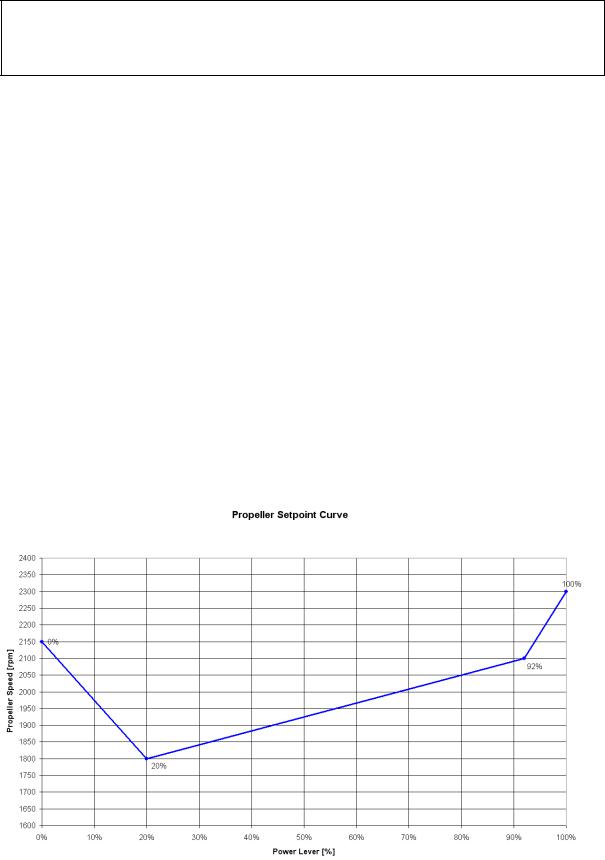
Propeller Control
The propeller pitch is controlled by the P-853-16 mt-propeller governor. The pitch is set by the ECU via an electro-mechanical actuator on the governor. To change the blade pitch angle, gearbox oil is pumped into the propeller hub which leads to an increase in pitch and a lower propeller RPM. When oil leaves the propeller hub pitch is reduced and RPM will increase.
In flight depending on the power setting the propeller pitch is adjusted such that the required RPM will be obtained as shown in the following diagram.
Doc. # 6.01.15-E |
Rev. 3 |
01-Jul-2014 |
Page 7 - 25 |
|
|
|
|

Airplane
DA 40 NG AFM
Description
Ground Operation:
CAUTION
Operation on the ground at high RPM should be avoided as far as possible, as the blades could suffer stone damage. For this reason a suitable site for engine runs should be selected, where there are no loose stones or similar items.
WARNING
Never rotate the propeller by hand.
Page 7 - 26 |
Rev. 3 |
01-Jul-2014 |
|
Doc. # 6.01.15-E |
|
|
|
|
|