

02 BOPs / NFPA 15.2007 plain text Edition
.pdfdepartmental official may be the authority having jurisdiction.
A.3.2.3 Listed. The means for identifying listed equipment may vary for each organization concerned with product evaluation; some organizations do not recognize equipment as listed unless it is also labeled. The authority having jurisdiction should utilize the system employed by the listing organization to identify a listed product.
A.3.3.9 Fire Area. The physical separations also include diking and special drainage systems.
A.3.3.12.1 Insulated. Noncombustible materials affording 2hour fire ratings under NFPA 251, Standard Methods of Tests of Fire Resistance of Building Construction and Materials, will usually satisfy the requirements of Chapter 5 when properly fastened and weather protected. For equipment, structures, and vessels of nonferrous metals, somewhat lower temperature limits than indicated in Chapter 5 might be required, based upon reliable metallurgical data.
A.3.3.14 Nonabsorbing Ground. Most soils are not considered sufficiently permeable or absorbent to be considered absorbing ground. Paving, such as concrete or asphalt, is considered nonabsorbing.
A.3.3.20.2 Open Water Spray Nozzle. A water spray nozzle is usually a discharge device with an open waterway. However, it is possible for nozzles to be equipped with operating elements such as fusible links or glass bulbs for special applications.
A.3.3.21 Water Spray System. Automatic systems can be actuated by separate detection equipment installed in the same area as the water spray nozzles or by the water spray nozzles using an operating element. In some cases, the automatic detector can also be located in another area.
A.3.3.22 Water Wastage. Some causes of wastage are wind velocity and sometimes the overcarry of discharge pattern beyond the targeted surface.
A.4.1 The design objectives are as follows:
(1)Extinguishment of fire by water spray is accomplished by cooling, smothering from produced steam, emulsification of some liquids, dilution in some cases, or a combination of these factors.
(2)Control of fires is accomplished by an application of water spray to the burning materials, producing controlled burning. The principle of control can be applied where combustible materials are not susceptible to complete extinguishment by water spray or where complete extinguishment is not considered desirable.
(3)Effective exposure protection is accomplished by application of water spray directly to the exposed structures or equipment to remove or reduce the heat transferred to them from the exposing fire. Water spray curtains are less effective than direct application but can, under favorable conditions, provide some protection against fire exposure through subdivision of fire areas. Unfavorable conditions can include such factors as windage, thermal updrafts, and inadequate drainage.
(4)Start of fire is prevented by the use of water sprays to dissolve, dilute, disperse, or Copyright NFPA
cool flammable materials or to reduce flammable vapor concentrations below the lower flammable limit (LFL).
A.4.2.3 See NFPA 49, Hazardous Chemicals Data, and NFPA 325, Guide to Fire Hazard Properties of Flammable Liquids, Gases, and Volatile Solids. (Note: Although NFPA 49 and 325 have been officially withdrawn from the National Fire Codes, the information is still available in NFPA’s Fire Protection Guide to Hazardous Materials.)
A.4.2.5 In special cases, where adequate safeguards have been provided, water spray systems for the protection of structures, equipment, or personnel in the presence of such materials as described in 4.2.5 might be acceptable.
A.4.3 Water spray system installation is a specialized field that is a trade in itself.
A.4.4.1 The rapid removal of spills and fire protection water from the area protected by a water spray system can greatly reduce the amount of fuel involved in a fire. In addition, if water discharge is not controlled, hydrocarbons or other liquid fuels can spread into adjacent areas and increase the size of the fire, exposing additional property and making the fire more difficult to control or extinguish.
An example of a protected hazard that might not require a system for controlling or containing water spray discharge would be a rubber belt conveyor located in an aboveground conveyor housing.
A.4.4.3 Each of the methods listed has advantages and disadvantages. In most cases, a combination of methods should be used in designing an effective control or containment system.
The characteristics of any hazardous materials in the protected area should be considered in the design of a control or containment system, including volume, solubility in water, flammability, reactivity, environmental concerns (e.g., toxicity), and vapor pressure at ambient and normal processing conditions. For example, particular attention should be given to the removal of burning flammable liquids away from process vessels containing reactive materials sensitive to heat.
Curbing, along with appropriate grading, can be of significant benefit in preventing water or burning liquid from spreading horizontally into adjacent areas. Grading should ideally be sloped at a pitch not less than one percent away from critical equipment and toward drains, trenches, ditches, or other safe area. Concrete surfacing is most desirable, but other hard surfacing or crushed rock or equivalent is suitable.
Process areas and buildings handling hydrocarbons or hazardous chemicals normally have a closed drain system to capture leaks, spills, normal drainage, wash down, and so forth. In some cases, it might not be practical to design the closed drain system to accommodate the full flow from the fire protection systems. Additionally, even where designed with adequate capacity, floor drains will often become clogged with debris during a fire. The excess that cannot be carried off by the closed drain system will then overflow to the surface drainage systems, which might include storm sewers, open ditches, streets, or similar features. The proper design of area drainage should anticipate where the excess will flow so that it can be safely routed and controlled.
Copyright NFPA

See NFPA 30, Flammable and Combustible Liquids Code, for diking requirements for the tank storage of flammable and combustible liquids.
Diking is not a desirable means of containing water spray discharge where buildings, process structures, or important equipment are being protected from exposure to flammable or combustible liquids.
A.4.4.4 Underground or enclosed drains are preferred over open trenches since enclosed drains provide a method of removing spilled liquids from the area without exposing equipment to burning liquids. Further, trenches can act as collection points for heavierthanair vapors. If used, trenches should be routed in a way that will not carry fire protection water and burning liquids through another fire area. If unavoidable, fire stops (weirs) should be provided in the trench system between the fire areas.
Trenches should be twice as wide as deep, and in no case should the depth exceed the width. Trenches should be provided with covers that are onethird open grating and twothirds solid plate or concrete. (See Figure A.4.4.4.)
 FIGURE A.4.4.4 Drainage Trench Detail.

 Drains should be in sufficient number that the required runoff is handled without formation
 of significant pools.
 A.4.4.7(1) The actual flow rate can be determined by plotting the demand curve (fixed
water supply systems) and the water supply curve on semiexponential (N1.85) graph paper.
 The intersection of the demand curve and the supply curve provides a realistic estimate of
 the actual flow rate that would be anticipated.
 A.4.4.7(5) Judgment should be used in determining the chance of having a major fire
simultaneous with a heavy rainfall. For areas experiencing little rainfall, drainage calculations
 can ignore rainfall. For areas experiencing frequent rainfall, a flow rate from rainfall might or
might not be warranted, depending on the hazards being protected and other factors. If
 included, a rainfall rate less than the highest anticipated would ordinarily be used, as it is not
likely that the maximum fire and rainfall demands would occur simultaneously. The effect of
 rainfall on the size of any areas designed to contain runoff should also be considered.

 A.4.4.8 It is desirable to contain runoff for the anticipated duration of any fire. However, in
Copyright NFPA

large chemical or petrochemical facilities, a major fire can last for 8 hours or more, resulting in extremely large holding basins or retention ponds. Where the anticipated incident duration results in retention basins that are of impractical size, methods to limit the duration of runoff might be required.
When an extended duration is anticipated, a duration of 4 hours is usually considered the practical maximum. During that time, it is often possible to isolate equipment and reduce the flow rate of water and other materials so that the continuous discharge flow rate is less than the initial flow rate. If a significant amount of flammable materials can be removed from the protected area, it could be possible to shut down water spray systems and manually fight the fire, greatly reducing the amount of material that needs to be contained.
Smaller facilities with limited holdups might not require as long a duration. For example, if the exposing fire is caused by a spill of 500 gal (1893 L) or less, with good drainage and containment systems, the anticipated duration could be as little as 30 minutes to 1 hour. In special circumstances (e.g., involving prompt manual response), an anticipated duration less than 30 minutes would be acceptable.
Finally, other standards and regulations might dictate the amount of containment required. For example, NFPA 30, Flammable and Combustible Liquids Code, contains requirements for warehouses and other areas containing flammable liquids. Also, local environmental regulations and building codes might contain criteria for duration and amount of material to be collected.
A.5.2.3.3 Painting of spray nozzles can retard the thermal response of the heatresponsive element, can interfere with the free movement of parts, and can render the spray nozzle inoperative. Moreover, painting can invite the application of subsequent coatings, thus increasing the possibility of altering the discharge pattern for all types of nozzles.
A.5.2.5 The stock of spare automatic water spray nozzles and pilot sprinklers should take into consideration the intended system performance, the criticality of the operations, and the down time associated with system impairment after damage or fire. Automatic water spray nozzles could have long lead times, delaying replacement of large numbers of nozzles for several weeks.
A.5.3.2 See Table A.5.3.2.
|
|
|
|
|
Table A.5.3.2 |
Steel Pipe Dimensions |
|||
|
|
|
|
Schedule 10* |
|
|
Schedule 30 |
||
|
Outside |
Inside |
Wall |
|
Inside |
|
|||
|
Diameter |
Diameter |
Thickness |
Diameter |
T |
||||
Nominal |
|
|
|
|
|
|
|
|
|
Pipe Size |
|
|
|
|
|
|
|
|
|
(in.) |
in. |
mm |
in. |
mm |
in. |
mm |
in. |
mm |
in. |
1 |
1.315 |
33.4 |
1.097 |
27.9 |
0.109 |
2.8 |
— |
— |
— |
1 ¼ |
1.660 |
42.2 |
1.442 |
36.6 |
0.109 |
2.8 |
— |
— |
— |
1 ½ |
1.900 |
48.3 |
1.682 |
42.7 |
0.109 |
2.8 |
— |
— |
— |
2 |
2.375 |
60.3 |
2.157 |
54.8 |
0.109 |
2.8 |
— |
— |
— |
2 ½ |
2.875 |
73.0 |
2.635 |
66.9 |
0.120 |
3.0 |
— |
— |
— |
Copyright NFPA

|
|
|
|
|
Table A.5.3.2 |
Steel Pipe Dimensions |
|||
|
|
|
|
Schedule 10* |
|
|
Schedule 30 |
||
|
Outside |
Inside |
Wall |
|
Inside |
|
|||
|
Diameter |
Diameter |
Thickness |
Diameter |
T |
||||
Nominal |
|
|
|
|
|
|
|
|
|
Pipe Size |
|
|
|
|
|
|
|
|
|
(in.) |
in. |
mm |
in. |
mm |
in. |
mm |
in. |
mm |
in. |
3 |
3.500 |
88.9 |
3.260 |
82.8 |
0.120 |
3.0 |
— |
— |
— |
3 ½ |
4.000 |
101.6 |
3.760 |
95.5 |
0.120 |
3.0 |
— |
— |
— |
4 |
4.500 |
114.3 |
4.260 |
108.2 |
0.120 |
3.0 |
— |
— |
— |
5 |
5.563 |
141.3 |
5.295 |
134.5 |
0.134 |
3.4 |
— |
— |
— |
6 |
6.625 |
168.3 |
6.357 |
161.5 |
0.134† |
3.4 |
— |
— |
— |
8 |
8.625 |
219.1 |
8.249 |
209.5 |
0.188† |
4.8 |
8.071 |
205.0 |
0.277 |
10 |
10.750 |
273.1 |
10.370 |
263.4 |
0.188† |
4.8 |
10.140 |
257.6 |
0.307 |
*Schedule 10 defined to 5 in. (125 mm) nominal pipe size by ASTM A 135, Standard Specification for Electr
†Wall thickness specified in 5.3.2.
A.5.3.5 Other types of pipe and tube that have been investigated and listed for water spray applications include lightweight steel pipe. While these products can offer advantages, such as ease of handling and installation, costeffectiveness, and reduction of friction losses, it is important to recognize that they also have limitations that are to be considered by those contemplating their use or acceptance.
Corrosion studies for lightweight steel pipe have shown that, in comparison to Schedule 40 pipe, its effective life might be reduced, with the level of reduction being related to its wall thickness. Further information with respect to corrosion resistance is contained in the individual listings of such products.
The investigation of pipe and tube other than described in Table 5.3.1 should involve consideration of many factors, including the following:
(1)Pressure rating
(2)Beam strength (hangers and spacing)
(3)Unsupported vertical stability
(4)Movement during system operation (affecting water distribution)
(5)Corrosion (internal and external), chemical and electrolytic
(6)Resistance to failure where exposed to elevated temperatures
(7)Methods of joining (strength, permanence, fire hazard)
(8)Physical characteristics related to integrity during earthquakes
(9)Resistance to mechanical and, where applicable, explosion damage
(10)Susceptibility to degradation due to environmental exposure (ultraviolet degradation
Copyright NFPA
and low temperatures, etc.)
A.5.4.10 Rubbergasketed pipe fittings and couplings should not be installed where ambient temperatures can be expected to exceed 150°F (66°C) unless listed for this service. If the manufacturer further limits a given gasket compound, those recommendations should be followed.
A.5.5.1.2 Some steel piping material having lesser wall thickness than specified in 5.5.1.2 has been listed for use in water spray systems when joined with threaded connections. The service life of such products can be significantly less than that of Schedule 40 steel pipe, and it should be determined if this service life will be sufficient for the application intended.
All such threads should be checked by the installer, using working ring gauges conforming to the Table 8, Basic Dimensions of Ring Gauges for USA (American) Standard Taper Pipe Threads, NPT, in accordance with ANSI/ASME B1.20.1, Pipe Threads, General Purpose, 1983.
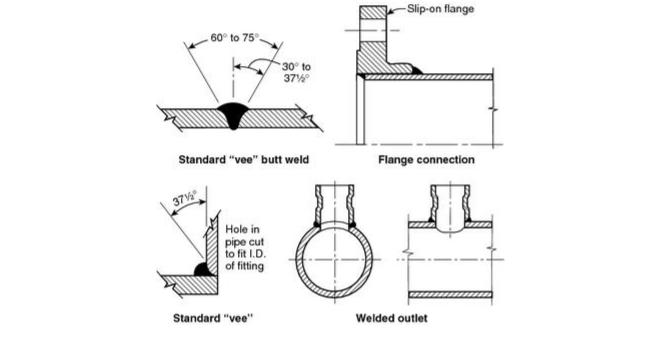
A.5.5.2 See Figure A.5.5.2(a) and Figure A.5.5.2(b).
 FIGURE A.5.5.2(a) Acceptable Weld Joints.

Copyright NFPA
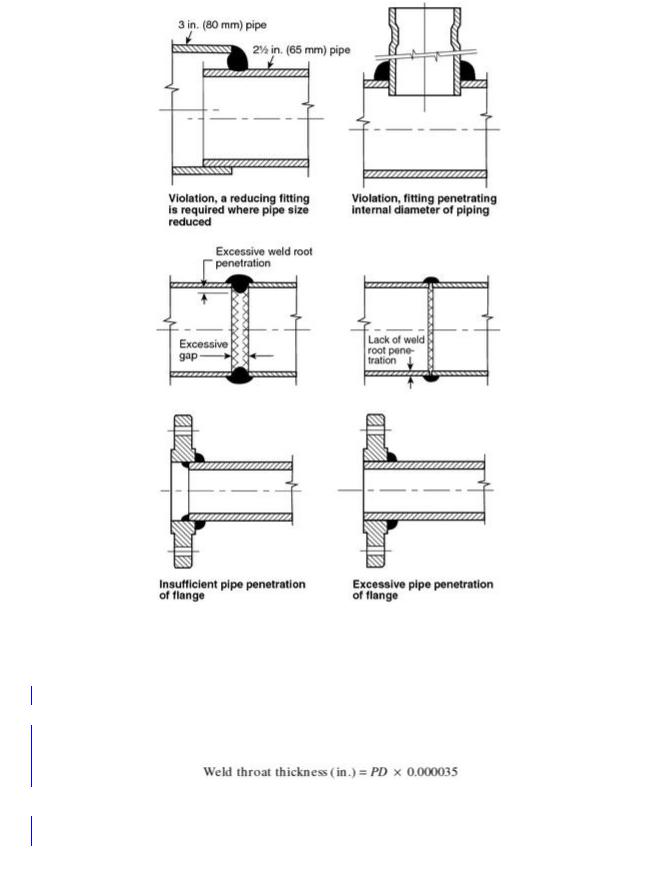
 FIGURE A.5.5.2(b) Unacceptable Weld Joints. [For correct pipe penetration of
 flange, see Figure A.5.5.2(a).]
 A.5.5.2.4.1 Partial penetration welds on outlet fitting connections are considered adequate
since there is no significant load on the joint other than that caused by pressure internal to
 the pipe. The load due to the internal pressure can be accommodated with a weld that has a
 conservative weld throat thickness, which can be calculated as follows:
 where:

 P = rated system pressure (psig)
 D = outside diameter of the fitting (in.)

Copyright NFPA
 For example, if you assume a pressure of 300 psi and an O.D. of the outlet fitting of 3 in., the result of the thickness calculation is 0.0315 in. When compared to the minimum throat
thickness of |
in. (0.18 in.), there is a factor of more than 5 times the calculated thickness |
value. |
|
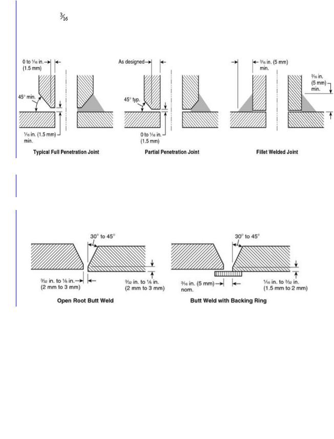
 See Figure A.5.5.2.4.1.
 FIGURE A.5.5.2.4.1 Acceptable Joint Configurations for Welding Outlets.

 A.5.5.2.4.2 The preparation of mating surfaces is important to the proper fabrication of a
weld joint. To accomplish this, the mating surfaces should be prepared and configured to be
 able to make a full penetration weld achievable, but a partial penetration weld is acceptable.

 A.5.5.2.4.3 See Figure A.5.5.2.4.3.
 FIGURE A.5.5.2.4.3 Acceptable Joint Configuration for Butt Welds.

 A.5.5.4 The fire hazard of the brazing process should be suitably safeguarded.

 A.5.5.4.1 Brazing fluxes, if used, should not be of a highly corrosive type.

 A.5.7.2.1 These valves include, but are not limited to, deluge valves, alarm check valves,
 preaction valves, and highspeed valves.
 A.5.7.2.2 Accessories can include any one of or a combination of the following:

 (1)
(1) Manual emergency stations

 (2)
(2) Flammable gas detectors

 (3)
(3) Smoke detectors

Copyright NFPA

(4)Heat detectors
(5)Fire detectors
(6)Control panels
Where installing wet pilot systems, special attention should be given to height limitations above the system actuation valve due to concern of water column. Refer to manufacturer’s information and listing.
A.5.7.2.3 Manual means of actuation can include pneumatic, hydraulic, electrical, mechanical, or any combination thereof.
A.5.9.1 The strainer should be capable of continued operation without serious increase in head loss for a period estimated to be ample for the type of protection provided, the condition of the water, and similar local circumstances.
 A.5.10.1.1 The purpose of the fire department connection is to augment the water supply,
but not necessarily provide the entire sprinkler system demand. Fire department connections
 are not intended to deliver a specific amount of water.

 A.5.11.3 All alarm apparatus should be located and installed such that all parts are
 accessible for inspection, removal, and repair and should be adequately supported.
 A.6.1.2 The minimum clearances listed in Table 6.1.2.2 are for the purpose of electrical
clearance under normal conditions; they are not intended for use as “safe” distances during
 fixed water spray system operation.

 The clearances are based upon minimum general practices related to design basic insulation
level (BIL) values. To coordinate the required clearance with the electrical design, the design
 BIL of the equipment being protected should be used as a basis, although this is not material
 at nominal line voltages of 161 kV or less.
 Up to electrical system voltages of 161 kV, the design BIL kV and corresponding minimum
 clearances, phase to ground, have been established through long usage.
 At voltages higher than 161 kV, uniformity in the relationship between design BIL kV and
the various electrical system voltages has not been established in practice. For these higher
 system voltages, it has become common practice to use BIL levels dependent on the degree
of protection that is to be obtained. For example, in 230 kV systems, BILs of 1050, 900,
 825, 750, and 650 kV have been utilized.

 Required clearance to ground can also be affected by switching surge duty, a power system
design factor that along with BIL should correlate with selected minimum clearances.
 Electrical design engineers might be able to furnish clearances dictated by switching surge
duty. Table 6.1.2.2 deals only with clearances required by design BIL. The selected clearance
 to ground should satisfy the greater of switching surge or BIL duty, rather than being based
 upon nominal voltage.
 Possible design variations in the clearance required at higher voltages are evident in the table,
where a range of BIL values is indicated opposite the various voltages in the high voltage
 portion of the table. However, the clearance between uninsulated energized parts of the
 Copyright NFPA

electrical system equipment and any portion of the water spray system should not be less than the minimum clearance provided elsewhere for electrical system insulation on any individual component.
A.6.2.1 Water spray systems are usually applied to special fire protection problems beyond the capability of a standard sprinkler system. They are specifically designed for fire control, extinguishment, prevention, or exposure protection. These systems typically require that the water be applied rapidly to all protected surfaces at the same time, an objective that might not be possible with closed nozzles. In addition, to protect specific surfaces, the use of special nozzles with directional discharge is employed. The placement of these nozzles to provide proper coverage is often in conflict with the required placement to ensure prompt operation where automatic nozzles are used. Thus, the standard contemplates that open nozzles will normally be employed and that a separate detection system will be used to actuate the system.
There are cases, however, where it is desirable to use closed nozzles to limit the discharge of water to prevent equipment damage (such as when water spray is used to protect turbine bearings), or there are environmental concerns. Automatic nozzles should only be used where open nozzles present such problems and the position of the nozzles can meet both the coverage and response time design objectives.
A.6.3.2.2.1 See Figure A.6.3.2.2.1.
 FIGURE A.6.3.2.2.1 Typical Arrangement of Support Legs for Pipe Stands.

 A.6.3.2.2.2 See Figure A.6.3.2.2.2.

Copyright NFPA