

02 BOPs / NFPA 15.2007 plain text Edition
.pdf0.25 gpm/ft2 [10.2 (L/min)/m2] over the wetted area. (See Figure 7.4.3.1.)
7.4.3.5Vertical structural steel that has been encased in fireresistant insulating material to provide a level of fire resistance acceptable to the authority having jurisdiction shall not require water spray protection.
7.4.3.6Alternative Engineering Analysis for Vertical Structural Steel. Vertical structural steel shall not require water spray exposure protection where all of the following are met:
(1)Vertical structural steel shall be analyzed and determined, through calculations certified by a registered professional engineer, to withstand the worstcase postulated fire.
(2)Calculations shall verify that the temperature of the steel members does not exceed that which would compromise structural integrity.
(3)The calculation methodology shall be approved and acceptable to the authority having jurisdiction.
7.4.3.7 Metal Pipe, Tubing, and Conduit.
7.4.3.7.1Water spray intended to protect metal pipe, tubing, and conduit in racks shall be directed toward the underside of the pipes, tubes, and conduit.
7.4.3.7.2Water spray protection shall be permitted to be applied to the top of pipes on racks where water spray piping cannot be installed below the rack due to the potential of physical damage or where space is inadequate for proper installation.
7.4.3.7.3The levels protected and the densities required shall be in accordance with Table
|
Table 7.4.3.7.3 |
Protection of Metal Pipe, Tubing, and Conduit |
|||
|
Plan View |
Plan View Density at |
|
||
|
Density at |
|
|||
|
Lowest Level |
Upper Level(s)* |
|
||
Number of |
gpm |
(L/min) |
gpm |
(L/min) |
Levels Requiring |
Rack Levels |
/ft2 |
/m2 |
/ft2 |
/m2 |
Nozzles |
1 |
0.25 |
10.2 |
N/A |
N/A |
All |
2 |
0.20 |
8.2 |
0.15 |
6.1 |
All |
3, 4, or 5 |
0.20 |
8.2 |
0.15 |
6.1 |
Alternate |
6 or more |
0.20 |
8.2 |
0.10 |
4.1 |
Alternate |
*The table values contemplate exposure from a spill fire.
7.4.3.7.4Water spray shall be applied to the underside of the top level even if located immediately above a protected level.
7.4.3.7.5Nozzles shall be selected and positioned such that spray patterns meet or overlap at the protected surface for the entire width of the rack.
7.4.3.7.6Nozzles shall be positioned no more than 2½ ft (0.8 m) below the bottom of the Copyright NFPA

level being protected.
7.4.3.7.7Where the rack horizontal support members create an obstruction to the spray pattern, nozzles shall be spaced within the bays.
7.4.3.7.8Vertical structural supports shall be protected in accordance with 7.4.3.4.
7.4.3.7.9Vertically stacked piping shall be protected by water spray directed at one side (vertical plane) of the piping at a net rate of not less than 0.15 gpm/ft2 [6.1 (L/min)/m2].
7.4.3.8 Cable Trays and Cable Runs.
7.4.3.8.1Where insulated wire, cable, or nonmetallic tubing in open trays or runs is to be protected by water spray from a spill fire exposure, a net rate of not less than 0.30 gpm/ft2 [12.2 (L/min)/m2] of projected horizontal or vertical plane area containing the cables or tubes shall be provided.
7.4.3.8.2Water spray nozzles shall be arranged to supply water at this rate both over and under (or to the front and rear of) cable or tubing runs and to the racks and supports.
7.4.3.8.3Flame Shield Use.
7.4.3.8.3.1 Where flame shields equivalent to  in. (1.6 mm) thick steel plate are mounted
 below cable or tubing runs, the water density requirements shall be permitted to be reduced
to a net rate of not less than 0.15 gpm/ft2 [6.1 (L/min)/m2] over the upper surface of the
 cable or rack.

 7.4.3.8.3.2 The steel plate or equivalent flame shield shall be wide enough to extend at least
6 in. (152 mm) beyond the side rails of the tray or rack in order to deflect flames or heat
 emanating from spills below cable or conduit runs.

 7.4.3.8.4 Where other water spray nozzles are arranged to extinguish, control, or cool
exposing liquid surfaces, the water spray density shall be permitted to be reduced to a net
 rate of not less than 0.15 gpm/ft2 [6.1 (L/min)/m2] over the upper surface, front, or back of
 the cable or tubing tray or run.
 7.4.4 Transformers.

 7.4.4.1*
 Transformer protection shall provide complete water spray impingement on all
 exposed exterior surfaces.
 7.4.4.2 Where there is insufficient space to install water spray nozzles underneath
transformers such that the water spray cannot directly impinge upon the bottom surfaces, it
 shall be permitted to protect the surfaces underneath the transformer by horizontal projection
 or by nozzles directed to cool the area below the transformer projections.
 7.4.4.3 Application and Protection.

 7.4.4.3.1 The water shall be applied at a net rate not less than 0.25 gpm/ft2 [10.2
(L/min)/m2] of projected area of rectangular prism envelope for the transformer and its
 appurtenances, and not less than 0.15 gpm/ft2 [6.1 (L/min)/m2] on the expected
 nonabsorbing ground surface area of exposure.
Copyright NFPA
7.4.4.3.2The water shall be applied at a net rate of not less than 0.15 gpm/ft2 [6.1(L/min)/m2] on the expected nonabsorbing ground surface area of exposure.
7.4.4.3.3Water spray application as specified in 7.4.4.3.1 and 7.4.4.3.2 shall be provided for special configurations, conservator tanks, pumps, and so forth.
7.4.4.3.4Where transformer components create spaces greater than 12 in. (305 mm) in width, the surfaces shall be individually protected.
7.4.4.3.5Where there is insufficient clearance to achieve direct impingement, it shall be permitted to protect the surfaces underneath the transformer by horizontal projection or by nozzles directed to cool the area below the transformer projections.
7.4.4.3.6The water supply shall be capable of supplying both the design flow rate and 250 gpm (946 L/min) for hose streams for a minimum duration of 1 hour.
7.4.4.4Water spray piping shall not be routed across the top of the transformer tank or across the face of the transformer cabinet.
7.4.4.5Piping shall be permitted to be routed across the top of the transformer tank or across the face of the transformer cabinet, where impingement cannot be accomplished with any other configuration and the required distance from live electrical components is maintained. (See 6.1.2.)
7.4.4.6Nozzles shall be positioned such that the water spray does not envelop energized bushings or lightning arresters by direct impingement.
7.4.4.7Direct impingement of water spray on energized bushings and/or lightning arresters shall be permitted only when authorized by the manufacturer or manufacturer’s literature and the owner.
7.5* Prevention of Fire.
7.5.1The system shall operate as intended for the time necessary to dissolve, dilute, disperse, or cool flammable vapor, gases, or hazardous materials.
7.5.2The duration of release of the flammable materials shall be included in the determination of the water spray duration time.
7.5.3The minimum net rate of application shall be based upon field experience with the product or upon actual test data.
7.6 Combined Systems.
7.6.1* General.
7.6.1.1The sprinkler system portion of combined systems shall be designed and installed in accordance with NFPA 13, Standard for the Installation of Sprinkler Systems.
7.6.1.2The water spray portion of any combined system shall be designed and installed in accordance with this standard.
7.6.2* Design.
Copyright NFPA

7.6.2.1The system demand shall include the simultaneous hydraulic demand from all sprinklers and water spray nozzles on the system.
7.6.2.2The water spray component of the combined demand shall not reduce the minimum required sprinkler discharge density.
7.7 Automatic Detection Equipment.
7.7.1* General. Detection systems providing an actuation signal to fixed water spray systems shall be designed in accordance with NFPA 72, National Fire Alarm Code.
7.7.2 The spacing, location, and position of detectors shall be in accordance with 6.5.2.
7.7.3* The following shall be evaluated when selecting and adjusting detection equipment:
(1)Normally changing conditions
(2)Nonfire temperature changes
7.7.4* Response Time.
7.7.4.1The detection system shall be designed to cause actuation of the system actuation valve to operate without delay.
7.7.4.2Where ambient conditions exist that cause false system operations, detection systems shall be permitted to include delays that would override these conditions.
 Chapter 8 Plans and Hydraulic Calculations

 8.1 General.

 8.1.1*
 Hydraulic calculations shall be conducted as part of the design of the piping system
 to determine that the required pressure and flow is available at each nozzle.
 8.1.2*
 Minimum operating pressure of any nozzle protecting outdoor hazard shall be 20 psi
 (1.4 bar).
 8.1.3 Nozzles protecting interior hazards shall have minimum operating pressures in
accordance with their listing.
 8.1.4*
 Except where permitted by 8.1.5, correction for velocity pressure shall be included in
 the calculations.
 8.1.5*
 The calculations shall be permitted to ignore velocity pressure corrections where the
 velocity pressure does not exceed 5 percent of the total pressure at each junction point.
 8.2 Working Plans.

 8.2.1 General.

 8.2.1.1 Working plans shall be submitted to the authority having jurisdiction before any
 equipment is installed or remodeled.
Copyright NFPA
8.2.1.2Deviation from approved plans shall require permission of the authority having jurisdiction.
8.2.1.3Working plans, including elevations, shall be drawn to an indicated scale, show all essential details, and include the following pertinent data as a minimum:
(1)The dates of initial submission and revisions.
(2)The name of the owner and occupant.
(3)The name and address of the contractor and layout technician.
(4)The location, including the street address.
(5)The point of the compass.
(6)The full height cross section.
(7)The structural features.
(8)The relative elevations of nozzles, junction points, and supply or reference points.
(9)Full information concerning water supplies, including such items as pumps, underground mains, earthquake protection, and flow test results.
(10)The make, type, size, location, position, and direction of spray nozzles.
(11)The make, type, model, and size of the system actuation valve, control valve, or special system valve. The method of control valve supervision shall be indicated on the plans.
(12)The type and location of alarm devices to be provided. The type and location of the control panel.
(13)The number of each size and type of spray nozzles on each system.
(14)The type of pipe and schedule of wall thickness, lengths of pipe, and whether center to center or cutting lengths are shown.
(15)The size and type of all fittings; the dimensions and locations of shopwelded sections.
(16)The sensing devices for detection, including the type, arrangement, and location.
(17)The hydraulic reference points shown on the plan shall correspond to comparable reference points on the hydraulic calculation sheets.
(18)The calculated system demand at a reference point.
(19)The total designed water demand with the number of systems designed to operate simultaneously at a reference point, preferably the source of supply, including hose streams and other fire protection equipment.
(20)The density requirements and hazard surface calculation, where applicable.
(21)The design objective of the system.
Copyright NFPA
(22)The make, type, and location of hangers, supports, sleeves, sway bracing, and inserts.
(23)All control and check valves, strainers, drain pipes, and test pipes.
(24)A graphic representation of the scale used on all plans.
(25)The weight or class, lining, and size of underground pipe, and the depth that the top of the pipe is to be laid below grade.
(26)Provisions for flushing underground pipe.
(27)Accurate and complete layout of the hazard to be protected.
8.2.1.4The working plan submittal shall include manufacturer’s installation instructions for any specially listed equipment, including descriptions, applications, and limitations for any nozzles, devices, piping, fittings, supports, and bracing materials.
8.2.1.5Where the equipment to be installed is an addition or change to an existing system, details of the existing system shall be indicated on the working plans to allow for review of the design and supporting hydraulic calculations.
8.3* Hydraulic Calculations.
8.3.1Hydraulic calculations shall be prepared on forms that include a summary sheet, detailed worksheet, and a graph sheet.
8.3.2Summary Sheet. The summary sheet [for sample summary sheet, see Figure B.1(a)] shall contain all of the following information where applicable:
(1)The date
(2)The location
(3)The name of the owner and occupant
(4)The building or plant number
(5)The description of the hazard
(6)The name and address of the contractor and calculator
(7)The name of the authority having jurisdiction
(8)The design purpose
(9)The rates of the water application (density) and applied areas in gpm/ft2 [L/min)/m2]
(10)The total system water requirements as calculated, including allowance for hose streams
(11)The total designed water demand with number of systems designed to operate simultaneously at a reference point, preferably the source of supply, including hose streams and other fire protection equipment
(12)Water supply information
8.3.3 Detailed Worksheets. Detailed worksheets or computer printout sheets [for sample Copyright NFPA
worksheet, see Figure B.1(b)] shall contain all of the following information:
(1)Sheet number, date, job number, and identification of calculations covered
(2)Description of discharge constant (K) (or provide the discharge curve or tabulation) for each nozzle type
(3)Hydraulic reference points
(4)Flow in gpm (L/min)
(5)Pipe size in in. (mm)
(6)Pipe lengths, center to center of fittings (or cut lengths) in ft (m)
(7)Equivalent pipe lengths for fittings and devices in ft (m)
(8)Friction loss in psi (bar) between reference points
(9)Total friction loss in psi (bar) between reference points
(10)Elevation head in psi (bar) between reference points
(11)Required pressure in psi (bar) at each reference point
(12)Velocity pressure and normal pressure if included in calculations
(13)Notes to indicate starting points, reference to other sheets, or to clarify data shown
(14)Combined Kfactor calculations for nozzles on drops, armovers, or sprigs where calculations do not begin at a nozzle
(15)Where extending existing equipment, hydraulic calculations indicating the previous design, volume, and pressure at points of connection, and adequate additional calculations to indicate effect on existing systems
8.3.4* Graph Sheet.
8.3.4.1The graph sheet shall be plotted on semilogarithmic graph paper (Q 1.85).
8.3.4.2Water supply curves and system requirements, plus hose demand if required, shall be plotted to present a graphic summary of the complete hydraulic calculation.
8.4 Water Supply Information.
The following information shall be included on the plans and calculations:
(1)Location and elevation of static and residual test gauge, with relation to the system actuation valve reference point
(2)Flow location
(3)Static pressure, psi (bar)
(4)Residual pressure, psi (bar)
(5)Flow, gpm (L/min)
Copyright NFPA
(6)Date
(7)Time
(8)Source of water flow test information
(9)Other sources of water supply, with pressure or elevation
8.5 Hydraulic Calculation Procedures.
8.5.1 Formulae.
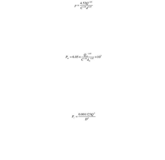
8.5.1.1 Friction Loss Formula. Pipe friction losses shall be determined on the basis of the Hazen and Williams formula,
 where:

 p = frictional resistance in psi per foot of pipe

Q = flow in gpm
 C = friction loss coefficient

d = actual internal diameter of pipe in inches  or in SI units,

 where:

 Pm = frictional resistance in bars per meter of pipe

Qm = flow in L/min
 C = friction loss coefficient
 dm = actual internal diameter in mm
8.5.1.2* Velocity Pressure Formula. The velocity pressure shall be determined on the basis  of the formula,

 where:

 Pv = velocity pressure in psi

Q = flow in gpm
 D = inside diameter in inches

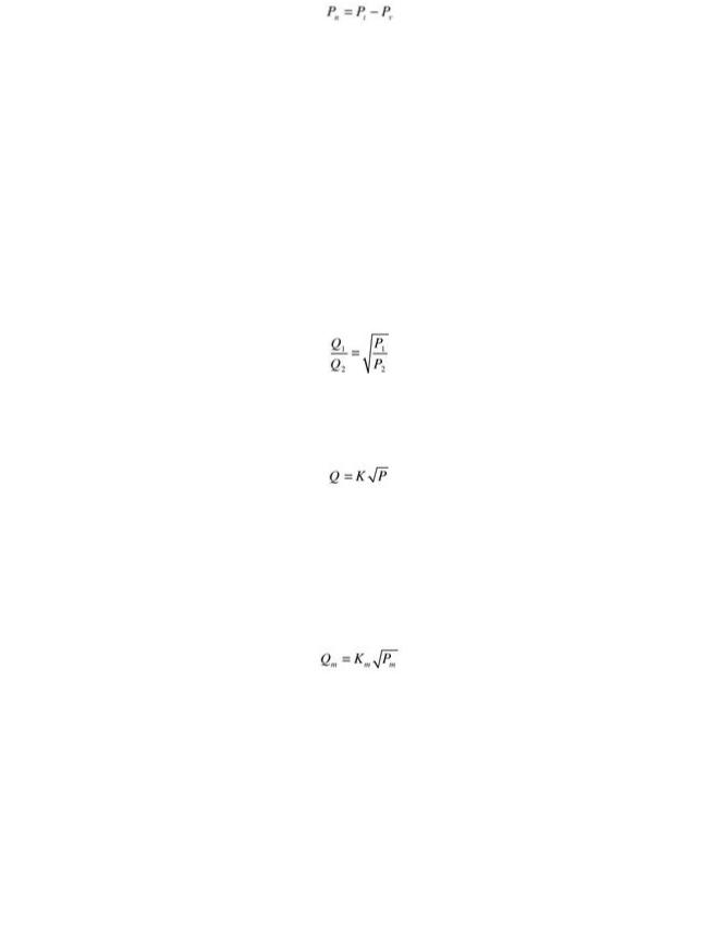
 8.5.1.3 Normal Pressure Formula. Normal pressure shall be determined on the basis of the
 formula,
Copyright NFPA
 where:

 Pn = normal pressure in psi (bar)

Pt = total pressure in psi (bar)
 Pv = velocity pressure in psi (bar)

 8.5.1.4 Hydraulic Junction Points.

 8.5.1.4.1 Hydraulic junction point calculations shall be balanced within 0.5 psi (0.03 bar).

 8.5.1.4.2 The highest pressure at the junction point, and the total flows as adjusted, shall be
 carried into the calculations.
 8.5.1.4.3 Hydraulic junction point calculations, except for loops, shall be balanced to the
 higher pressure by the formula (corrected for elevations),
 8.5.1.5 Nozzle Discharge Formula.

 8.5.1.5.1 The discharge of a nozzle shall be calculated by the formula,

 where:

 Q = gpm flowing from the nozzle

K = nozzle Kfactor
 P = total pressure in psi at the flow Q

 or in SI units,

 where:

 Qm = flow in L/min

Km = nozzle Kfactor (where Km equals 14.4 K)
 Pm = total pressure in bars at the flow Qm

 8.5.1.5.2 The normal pressure (Pn), calculated by subtracting the velocity pressure (Pv)
from the total pressure (Pt), shall be permitted to be used to calculate the nozzle discharge,
 unless the nozzle is an end nozzle, where total pressure (Pt) is permitted per 8.1.5.

 8.5.2 Equivalent Pipe Lengths of Valves and Fittings.

 8.5.2.1
 Table 8.5.2.1 shall be used to determine equivalent lengths of valves and fittings,
Copyright NFPA
n |
v |
from the total pressure (Pt), shall be permitted to be used to calculate the nozzle discharge, unless the nozzle is an end nozzle, where total pressure (Pt) is permitted per 8.1.5.
8.5.2 Equivalent Pipe Lengths of Valves and Fittings.
8.5.2.1 Table 8.5.2.1 shall be used to determine equivalent lengths of valves and fittings, unless the manufacturer’s test data indicates that other factors are appropriate.
Table 8.5.2.1 Equivalent Pipe Length Cha
|
|
|
|
Fittings and Valves Expressed in Equivalent F |
||||
|
|
¾ in. |
|
1 in. |
|
1¼ in. |
1½ in. |
|
Fittings and Valves |
ft |
m |
ft |
m |
ft |
m |
m |
ft |
45° Elbow |
1 |
0.3 |
1 |
0.3 |
1 |
0.3 |
2 |
0.6 |
90° Standard elbow |
2 |
0.6 |
2 |
0.6 |
3 |
0.9 |
4 |
1.2 |
90° Long turn elbow |
1 |
0.3 |
2 |
0.6 |
2 |
0.6 |
2 |
0.6 |
Tee or cross (flow turned |
4 |
1.2 |
5 |
1.5 |
6 |
1.8 |
8 |
2.4 |
90°) |
|
|
|
|
|
|
|
|
Gate valve |
— |
— |
— |
— |
— |
— |
— |
— |
Butterfly valve |
— |
— |
— |
— |
— |
— |
— |
— |
Swing check* |
4 |
1.2 |
5 |
1.5 |
7 |
2.1 |
9 |
2.7 |
|
|
|
|
Fittings and Valves Expressed in Equivalen |
||||
|
|
3½ in. |
4 in. |
|
|
5 in. |
|
6 in. |
Fittings and Valves |
ft |
m |
ft |
m |
ft |
m |
ft |
m |
45° Elbow |
3 |
0.9 |
4 |
1.2 |
5 |
1.5 |
7 |
2.1 |
90° Standard elbow |
8 |
2.4 |
10 |
3.1 |
12 |
3.7 |
14 |
4.3 |
90° Long turn elbow |
5 |
1.5 |
6 |
1.8 |
8 |
2.4 |
9 |
2.7 |
Tee or cross (flow turned |
17 |
5.2 |
20 |
6.1 |
25 |
7.6 |
30 |
9.2 |
90°) |
|
|
|
|
|
|
|
|
Gate valve |
1 |
0.3 |
2 |
0.6 |
2 |
0.6 |
3 |
0.9 |
Butterfly valve |
— |
— |
12 |
3.7 |
9 |
2.7 |
10 |
3.1 |
Swing check* |
19 |
5.8 |
22 |
6.7 |
27 |
8.2 |
32 |
9.8 |
*Due to the variations in design of swing check valves, the pipe equivalents indicated in this chart are to be co Notes:
(1)Use the equivalent ft (m) value for the “standard elbow” on any abrupt 90° turn such as the screwtype patt elbow” on any sweeping 90° turn such as flanged, welded, or mechanical joint elbow type.
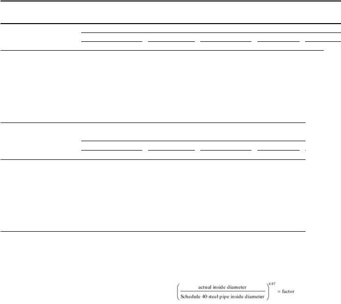
(2)For internal pipe diameters different from Schedule 40 steel pipe, the equivalent feet shown shall be multip
Copyright NFPA