

Архитектура и программирование микроконтроллеров (Шипатов) 2024 (Отсутствуют некоторые файлы, но все лабы вроде на месте) / Labs / Docs / STM / en.STM32L4_Analog_DAC
.pdfHello, and welcome to this presentation of the STM32L4 digital-to-analog converter. All the features of this analog block will be presented, which is used to convert digital signals to analog voltages which can interface with the external world.
1

The digital-to-analog converter on STM32L products ensures the conversion of 8- or 12-bit digital data to the analog voltage. Two DAC modules are embedded in the STM32L4 devices, except on STM32L45x/46x devices were only 1 DAC is implemented.
A low-power Sample and Hold mode is also integrated. The DAC can interface with external pots or bias circuitry. It can also create voice and arbitrary signals.
2

The digital-to-analog converter inside STM32L4 products offers simple digital-to-analog conversion in an 8- or 12bit mode; 10-bit monotonicity is guaranteed. The DAC output can have a low impedance buffer to drive external loads. Its Sample and Hold mode can reduce power consumption significantly. Two DACs can be synchronized with each other. The input data can be transferred by DMA which offloads the CPU. The DAC output data can be updated by a timer or an external trigger as well as a software trigger. It also integrates small logic to generate noise waves as well as triangle waves.
3
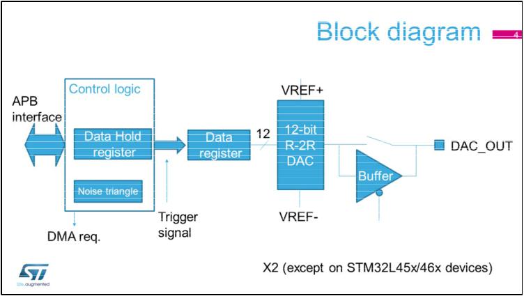
Here you can see the simplified block diagram of the digital-to-analog converter. The STM32L4 integrates 2 of them except on STM32L45x/46x devices were only 1 DAC is implemented.
4
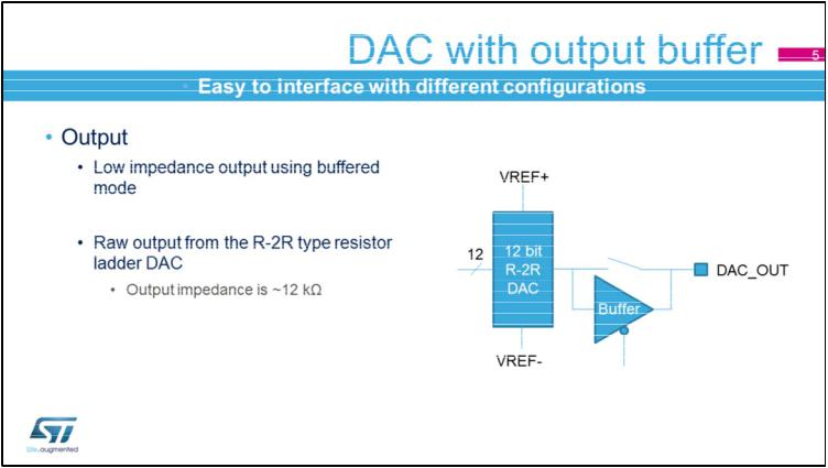
The DAC output can be buffered for low impedance loads. When unbuffered, the output is directly connected to the R-2R resistor ladder network type of DAC.
5
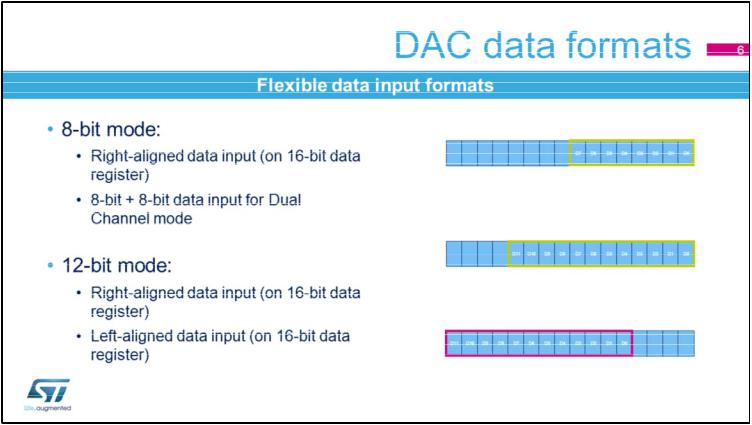
The DAC can support different input formats. In 8-bit mode, it’s a right-aligned 8-bit data format. In Dual channel mode , it’s an 8 bit plus 8 bit data format, in order to provide input data for two DAC simultaneously. In 12-bit mode, either a rightor left-aligned mode can be used for input data.
6
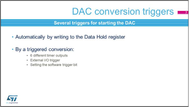
DAC output conversion is started by writing to the Data Hold register by software. 6 different timer outputs, an external I/O or software can trigger the DAC conversion.
7

The digital-to-analog converter has a Sample & Hold mode feature. The DAC can work intermittently, charge the external or internal capacitor, and be powered down while the output voltage is kept on the hold capacitor. After a certain period, the DAC is powered back on again and recharges the hold capacitor.
8
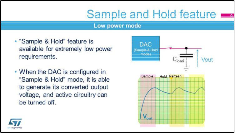
By doing so, the DAC is only active during very low duty cycles; resulting in very low power consumption. The duty cycle program is very flexible and autonomous.
9
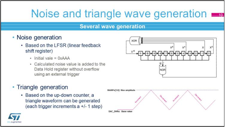
The DAC digital interface integrates two special signal generators. The Linear Feedback Shift register can create the noise signal for the DAC input. Each trigger updates the DAC output data by an LFSR block.
The up-down counter with a programmable count value can create triangle wave data which can update the DAC output data. The data can also be updated by a trigger signal.
10