

- •1 STM32Cube overview
- •2 Getting started with STM32CubeMX
- •2.1 Principles
- •2.2 Key features
- •2.3 Rules and limitations
- •3 Installing and running STM32CubeMX
- •3.1 System requirements
- •3.1.1 Supported operating systems and architectures
- •3.1.2 Memory prerequisites
- •3.1.3 Software requirements
- •Java™ Runtime Environment
- •macOS software requirements
- •3.2 Installing/uninstalling STM32CubeMX standalone version
- •3.2.1 Installing STM32CubeMX standalone version
- •3.2.2 Installing STM32CubeMX from command line
- •Interactive mode
- •Auto-install mode
- •3.2.3 Uninstalling STM32CubeMX standalone version
- •Uninstalling STM32CubeMX on macOS®
- •Uninstalling STM32CubeMX on Linux®
- •Uninstalling STM32CubeMX on Windows®
- •3.3 Launching STM32CubeMX
- •3.3.1 Running STM32CubeMX as a standalone application
- •3.4 Getting updates using STM32CubeMX
- •3.4.1 Running STM32CubeMX behind a proxy server
- •3.4.2 Updater configuration
- •3.4.3 Installing STM32 MCU packages
- •3.4.4 Installing STM32 MCU package patches
- •3.4.5 Installing embedded software packs
- •3.4.6 Removing already installed embedded software packages
- •3.4.7 Checking for updates
- •4 STM32CubeMX user interface
- •4.1 Home page
- •4.1.1 File menu
- •Table 2. Home page shortcuts
- •4.1.2 Window menu and Outputs tabs
- •Table 3. Window menu
- •4.1.3 Help menu
- •Table 4. Help menu shortcuts
- •4.1.4 Social links
- •4.2 New Project window
- •4.2.1 MCU selector
- •MCU selection
- •Export to Excel feature
- •Show favorite MCUs feature
- •MCU close selector feature
- •4.2.2 Board selector
- •4.2.3 Example selector
- •4.2.4 Cross selector
- •Part number selection
- •Compare cart
- •MCU/MPU selection for a new project
- •4.3 Project page
- •4.4 Pinout & Configuration view
- •Tips
- •4.4.1 Component list
- •Contextual help
- •Icons and color schemes
- •4.4.2 Component Mode panel
- •4.4.3 Pinout view
- •Tips and tricks
- •4.4.4 Pinout menu and shortcuts
- •4.4.5 Pinout view advanced actions
- •Manually modifying pin assignments
- •Manually remapping a function to another pin
- •Manual remapping with destination pin ambiguity
- •Resolving pin conflicts
- •4.4.6 Keep Current Signals Placement
- •Keep Current Signals Placement is unchecked
- •Keep Current Signals Placement is checked
- •4.4.7 Pinning and labeling signals on pins
- •4.4.8 Pinout for multi-bonding packages
- •4.4.9 System view
- •Table 7. Configuration states
- •4.4.10 Component configuration panel
- •Table 8. Peripheral and Middleware configuration window buttons and tooltips
- •No check option
- •4.4.11 User Constants configuration window
- •Creating/editing user constants
- •Deleting user constants
- •Searching for user constants
- •4.4.12 GPIO configuration window
- •4.4.13 DMA configuration window
- •4.4.14 NVIC configuration window
- •Enabling interruptions using the NVIC tab view
- •Code generation options for interrupt handling
- •4.4.15 FreeRTOS configuration panel
- •Tasks and Queues Tab
- •Timers, Mutexes and Semaphores
- •FreeRTOS heap usage
- •4.4.16 Setting HAL timebase source
- •Example of configuration using SysTick without FreeRTOS
- •Example of configuration using SysTick and FreeRTOS
- •Example of configuration using TIM2 as HAL timebase source
- •4.5 Pinout & Configuration view for STM32MP1 series
- •4.5.1 Run time configuration
- •4.5.2 Boot stages configuration
- •Boot ROM peripherals selection
- •Boot loader (A7 FSBL) peripherals selection
- •4.7 Enabling security in Pinout & Configuration view (STM32L5 and STM32U5 series only)
- •4.7.1 Privilege access for peripherals, GPIO EXTIs and DMA requests
- •4.7.3 NVIC and context assignment for peripherals interrupts
- •4.7.4 DMA (context assignment and privilege access settings)
- •4.7.5 GTZC
- •4.7.6 OTFDEC
- •4.8 Clock Configuration view
- •4.8.1 Clock tree configuration functions
- •External clock sources
- •Peripheral clock configuration options
- •Table 9. Clock configuration view widgets
- •4.8.2 Securing clock resources (STM32L5 series only)
- •4.8.3 Recommendations
- •Table 11. Voltage scaling versus power over-drive and HCLK frequency
- •Table 12. Relations between power over-drive and HCLK frequency
- •4.8.5 Clock tree glossary
- •4.9 Project Manager view
- •4.9.1 Project tab
- •4.9.2 Code Generator tab
- •STM32Cube Firmware Library Package option
- •Generated files options
- •HAL settings options
- •Custom code template options
- •4.9.3 Advanced Settings tab
- •Choosing not to generate code for some peripherals or middlewares
- •Ordering initialization function calls
- •Disabling calls to initialization functions
- •Choosing between HAL and LL based code generation for a given peripheral instance
- •4.10 Import Project window
- •4.11 Set unused / Reset used GPIOs windows
- •4.12 Update Manager windows
- •4.13 Software Packs component selection window
- •4.13.1 Introduction on software components
- •4.13.2 Filter panel
- •Table 14. Additional software window - Filter icons
- •4.13.3 Packs panel
- •Table 15. Additional Software window – Packs panel columns
- •4.13.4 Component dependencies panel
- •Table 17. Component dependencies panel contextual help
- •4.13.5 Details and Warnings panel
- •4.13.6 Updating the tree view for additional software components
- •4.14 LPBAM Scenario & Configuration view
- •4.15 CAD Resources view section
- •Access from MCU selector
- •Access from STM32CubeMX project view
- •4.16 Boot path
- •4.16.1 Available boot paths
- •Table 18. Boot paths without TrustZone (TZEN = 0)
- •Table 19. Boot paths with TrustZone (TZEN = 1)
- •4.16.2 Creating a boot path project: an example
- •Step 1: Selecting the MCU
- •Step 2: Project creation with OEM-iRoT boot path
- •Step 3: Device and peripherals configuration
- •Step 4: Overall configuration
- •Step 5: Boot path selection
- •Step 6: Authentication and encryption keys regeneration, option byte file generation
- •Step 7: Code generation
- •Step 8: Code compilation and encrypted binaries generation
- •Step 9: Provisioning of the board
- •Step 1: Generating the code
- •Step 2: Code compilation and encrypted binaries generation
- •ST-iRoT board provisioning
- •Step 1: SMAK code generation
- •SMAK code compilation and encrypted binaries generation
- •Secure manager API
- •4.16.6 How to configure an assembled boot path
- •Step 1: Configure flash_layout.h file
- •Step 2: Compile OEMiROT_Boot project
- •Step 3: Compile OEMiROT_Boot project
- •4.17 User authentication
- •4.17.1 Login with an existing my.st.com account
- •4.17.2 Create a my.st.com account
- •4.17.3 Authentication through command line interface
- •4.18 STM32CubeMX Memory Management Tool
- •Feature: MMT usage, Pinout, and Configuration UI
- •Feature: MMT usage and linker script
- •User interface
- •Region information
- •Code generation configuration
- •Apply Application Regions settings to linker files
- •Configuring an external memory
- •Configuring a memory region using the left panel
- •Setting up a middleware memory location
- •Remap
- •Code generation
- •4.19 About window
- •5 STM32CubeMX tools
- •5.1 External Tools
- •5.2 Power Consumption Calculator view
- •5.2.1 Building a power consumption sequence
- •Selecting a VDD value
- •Selecting a battery model (optional)
- •Power sequence default view
- •Managing sequence steps
- •Adding a step
- •Editing a step
- •Moving a step
- •Deleting a step
- •Using the transition checker
- •5.2.2 Configuring a step in the power sequence
- •Using interpolation
- •Importing pinout
- •Selecting/deselecting all peripherals
- •Managing the whole sequence (load, save and compare)
- •Managing the results charts and display options
- •Overview of the Results summary area
- •5.2.4 Power sequence step parameters glossary
- •5.2.5 Battery glossary
- •5.2.6 SMPS feature
- •5.2.7 BLE and ZigBee support (STM32WB series only)
- •5.3 DDR Suite (for STM32MP1 series only)
- •5.3.1 DDR configuration
- •DDR type, width and density
- •DDR configuration
- •DDR3 configuration
- •5.3.2 Connection to the target and DDR register loading
- •Prerequisites
- •Connection to the target
- •Output/Log messages
- •DDR register loading (optional)
- •5.3.3 DDR testing
- •Prerequisites
- •DDR test list
- •DDR test results
- •6 STM32CubeMX C Code generation overview
- •6.1 STM32Cube code generation using only HAL drivers (default mode)
- •6.2 STM32Cube code generation using Low Layer drivers
- •Table 20. LL versus HAL code generation: drivers included in STM32CubeMX projects
- •Table 21. LL versus HAL code generation: STM32CubeMX generated header files
- •Table 22. LL versus HAL: STM32CubeMX generated source files
- •6.3 Custom code generation
- •6.3.1 STM32CubeMX data model for FreeMarker user templates
- •6.3.2 Saving and selecting user templates
- •6.3.3 Custom code generation
- •6.4 Additional settings for C project generation
- •Possible entries and syntax
- •.extSettings file example and generated outcomes
- •[Groups]
- •[Others]
- •7 Code generation for dual-core MCUs (STM32H7 dual-core product lines only)
- •Generated initialization code
- •Generated startup and linker files
- •Generated boot mode code
- •8 Code generation with TrustZone® enabled (STM32L5 series only)
- •Specificities
- •9 Device tree generation (STM32MP1 series only)
- •9.1 Device tree overview
- •9.2 STM32CubeMX Device tree generation
- •10 Support of additional software components using CMSIS-Pack standard
- •11 Tutorial 1: From pinout to project C code generation using an MCU of the STM32F4 series
- •11.1 Creating a new STM32CubeMX Project
- •11.2 Configuring the MCU pinout
- •11.3 Saving the project
- •11.4 Generating the report
- •11.5 Configuring the MCU clock tree
- •11.6 Configuring the MCU initialization parameters
- •11.6.1 Initial conditions
- •11.6.2 Configuring the peripherals
- •11.6.3 Configuring the GPIOs
- •11.6.4 Configuring the DMAs
- •11.6.5 Configuring the middleware
- •11.7 Generating a complete C project
- •11.7.1 Setting project options
- •11.7.2 Downloading firmware package and generating the C code
- •11.8 Building and updating the C code project
- •11.9 Switching to another MCU
- •12 Tutorial 2 - Example of FatFs on an SD card using STM32429I-EVAL evaluation board
- •13 Tutorial 3 - Using the Power Consumption Calculator to optimize the embedded application consumption and more
- •13.1 Tutorial overview
- •13.2 Application example description
- •13.3 Using the Power Consumption Calculator
- •13.3.1 Creating a power sequence
- •13.3.2 Optimizing application power consumption
- •Step 1 (Run)
- •Step 4 (Run, RTC)
- •Step 5 (Run, ADC, DMA, RTC)
- •Step 6 (Sleep, DMA, ADC, RTC)
- •Step 7 (Run, DMA, RTC, USART)
- •Step 8 (Stop 0, USART)
- •Step 10 (RTC, USART)
- •14 Tutorial 4 - Example of UART communications with an STM32L053xx Nucleo board
- •14.1 Tutorial overview
- •14.2 Creating a new STM32CubeMX project and selecting the Nucleo board
- •14.3 Selecting the features from the Pinout view
- •14.4 Configuring the MCU clock tree from the Clock Configuration view
- •14.5 Configuring the peripheral parameters from the Configuration view
- •14.6 Configuring the project settings and generating the project
- •14.7 Updating the project with the user application code
- •14.8 Compiling and running the project
- •14.9 Configuring Tera Term software as serial communication client on the PC
- •15 Tutorial 5: Exporting current project configuration to a compatible MCU
- •16 Tutorial 6 – Adding embedded software packs to user projects
- •17 Tutorial 7 – Using the X-Cube-BLE1 software pack
- •Table 25. Connection with hardware resources
- •18 Creating LPBAM projects
- •18.1 LPBAM overview
- •18.1.1 LPBAM operating mode
- •18.1.2 LPBAM firmware
- •18.1.3 Supported series
- •18.1.4 LPBAM design
- •18.1.5 LPBAM project support in STM32CubeMX
- •18.2 Creating an LPBAM project
- •18.2.1 LPBAM feature availability
- •18.2.2 Describing an LPBAM project
- •18.2.3 Managing LPBAM applications in a project
- •18.3 Describing an LPBAM application
- •18.3.1 Overview (SoC & IPs configuration, runtime scenario)
- •SoC and IPs configuration
- •Runtime description (scenario)
- •18.3.2 SoC& IPs: configuring the clock
- •18.3.3 SoC & IPs: configuring the IPs
- •18.3.4 SoC & IPs: configuring Low Power settings
- •18.3.5 LPBAM scenario: managing queues
- •18.3.6 Queue description: managing nodes
- •18.3.7 Queue description: configuring the queue in circular mode
- •18.3.8 Queue description: configuring the DMA channel hosting the queue
- •Basic configuration
- •DMA channel NVIC configuration
- •18.3.9 Node description: accessing contextual help and documentation
- •18.3.10 Node description: configuring node parameters
- •18.3.11 Node description: configuring a trigger
- •18.3.12 Node description: reconfiguring a DMA for Data transfer
- •18.4 Checking the LPBAM design
- •18.5 Generating a project with LPBAM applications
- •18.6 LPBAM application for TrustZone activated projects
- •STM32CubeMX standard project view
- •STM32CubeMX LPBAM view
- •Security settings coherency check
- •19.1 I encountered a network connection error during a download from STM32CubeMX.
- •19.2 Since I changed my login to access the Internet, some software packs appear not available.
- •19.4 On the Pinout configuration panel, why does STM32CubeMX move some functions when I add a new peripheral mode?
- •19.5 How can I manually force a function remapping?
- •19.6 Why some pins are highlighted in yellow or in light green in the Pinout view? Why I cannot change the function of some pins (when I click some pins, nothing happens)?
- •19.7 Why does the RTC multiplexer remain inactive on the Clock tree view?
- •19.8 How can I select LSE and HSE as clock source and change the frequency?
- •19.9 Why STM32CubeMX does not allow me to configure PC13, PC14, PC15, and PI8 as outputs when one of them is already configured as an output?
- •19.10 Ethernet configuration: why cannot I specify DP83848 or LAN8742A in some cases?
- •19.11 How to fix MX_DMA_Init call rank in STM32CubeMX generated projects?
- •19.12 When is the PeriphCommonClock_Config() function generated?
- •Appendix A STM32CubeMX pin assignment rules
- •A.1 Block consistency
- •Example of block mapping with an STM32F107x MCU
- •Example of block remapping with an STM32F107x MCU
- •A.2 Block inter-dependency
- •Example of block remapping of SPI in full-duplex master mode with an STM32F107x MCU
- •A.3 One block = one peripheral mode
- •Example of STM32F107x MCU
- •A.4 Block remapping (STM32F10x only)
- •Example
- •A.5 Function remapping
- •Example using STM32F415x
- •A.6 Block shifting (only for STM32F10x and when “Keep Current Signals placement” is unchecked)
- •Example
- •A.7 Setting and clearing a peripheral mode
- •A.8 Mapping a function individually
- •A.9 GPIO signals mapping
- •Appendix B STM32CubeMX C code generation design choices and limitations
- •B.2 STM32CubeMX design choices for peripheral initialization
- •B.3 STM32CubeMX design choices and limitations for middleware initialization
- •B.3.1 Overview
- •B.3.5 FreeRTOS
- •B.3.6 LwIP
- •B.3.7 Libjpeg
- •B.3.8 Mbed TLS
- •B.3.9 TouchSensing
- •B.3.11 STM32WPAN BLE/Thread (STM32WB series only)
- •BLE configuration
- •Thread configuration
- •B.3.12 CMSIS packs selection limitation
- •Appendix C STM32 microcontrollers naming conventions
- •Appendix D STM32 microcontrollers power consumption parameters
- •D.1 Power modes
- •D.1.1 STM32L1 series
- •D.1.3 STM32L0 series
- •D.2 Power consumption ranges
- •D.2.1 STM32L1 series features three VCORE ranges
- •D.2.2 STM32F4 series features several VCORE scales
- •D.2.3 STM32L0 series features three VCORE ranges
- •Appendix E STM32Cube embedded software packages
- •Revision history
Code generation with TrustZone® enabled (STM32L5 series only) |
UM1718 |
8Code generation with TrustZone® enabled (STM32L5 series only)
In STM32CubeMX project manager view, all project generation options remain available.
However, the choice of toolchains is limited to the IDEs/compilers supporting the Cortex®-M33 core:
•EWARM v8.32 or higher
•MDK-ARM v5.27 or higher (ARM compiler 6)
•STM32CubeIDE (GCC v4.2 or higher)
Upon product selection, STM32CubeMX requires to choose between enabling TrustZone® or not.
•When TrustZone® is enabled, STM32CubeMX generates two C projects: one secured and one non-secured. After compilation, two images are available for download, one for each context.
•When TrustZone® is disabled, STM32CubeMX generates a non-secured C project, as for other products not supporting it.
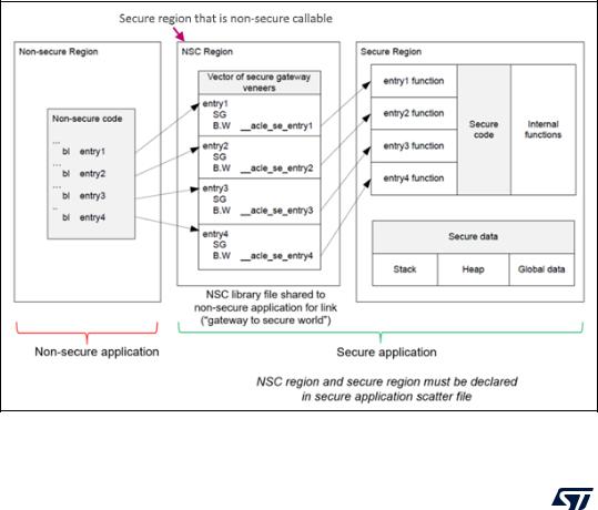
Specificities
When TrustZone® is enabled, the project generation must be adjusted to ensure that secure and non-secure images can be built.
Figure 295. Building secure and non-secure images with ARMv8-M TrustZone®
276/453 |
UM1718 Rev 41 |
UM1718 |
Code generation with TrustZone® enabled (STM32L5 series only) |
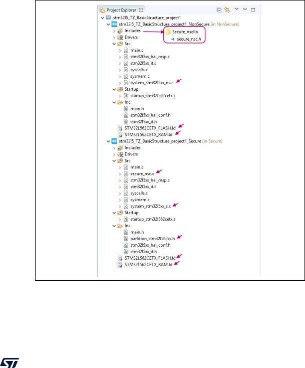
When TrustZone® is enabled for the project, STM32CubeMX generates three folders:
•NonSecure for non-secure code
•Secure for secure code
•Secure_nsclib for non-secure callable region
See Figure 296 (use TZ_BasicStructure_project_inCubeIDE.png) and Figure 297 (use
STM32L5_STM32CubeMX_Project_settings_inCubeIDE.png).
Figure 296. Project explorer view for STM32L5 TrustZone® enabled projects
UM1718 Rev 41 |
277/453 |

Code generation with TrustZone® enabled (STM32L5 series only) |
UM1718 |
Figure 297. Project settings for STM32CubeIDE toolchain
STM32CubeMX also generates specific files, detailed in Table 24.
Table 24. Files generated when TrustZone® is enabled
File |
Folder |
Details |
|
|
|
|
|
|
|
Initial setup for secure / non-secure zones for |
|
The product core secure/non-secure |
|
ARMCM33 based on CMSIS CORE V5.3.1 |
|
|
partition_ARMCM33.h Template. |
||
partitioning .h “template” file |
Secure |
It initializes Security attribution unit (SAU) |
|
Example: partition_stm32l552xx.h |
|
CTRL register, setup behavior of Sleep and |
|
|
|
Exception Handling, Floating Point Unit and |
|
|
|
Interrupt Target. |
|
|
|
|
|
|
|
Must be filled by the user with the list of |
|
|
|
non-secure callable APIs. |
|
secure_nsc.h file |
Secure_nsclib |
Templates are available as reference in |
|
|
|
STM32L5Cube embedded software package |
|
|
|
in Templates\TrustZone®\Secure_nsclib |
|
|
|
folders. |
|
|
|
|
|
|
|
CMSIS Cortex-M33 device peripheral access |
|
System_stm32l5xx_s.c |
Secure |
layer system source file to be used in secure |
|
application when the system implements |
|||
|
|
||
|
|
security. |
|
|
|
|
278/453 |
UM1718 Rev 41 |

UM1718 |
Code generation with TrustZone® enabled (STM32L5 series only) |
||
|
Table 24. Files generated when TrustZone® is enabled (continued) |
||
|
File |
Folder |
Details |
|
|
|
|
|
|
|
CMSIS Cortex-M33 device peripheral access |
|
System_stm32l5xx_ns.c |
NonSecure |
layer system source file to be used in |
|
non-secure application when the system |
||
|
|
|
|
|
|
|
implements security. |
|
|
|
|
|
STM32L562CETX_FLASH |
|
Linker files for the secure and non-secure |
|
|
memory layouts. |
|
|
STM32L562CETX_RAM |
|
|
|
Secure, |
File extensions and naming conventions: |
|
|
or |
||
|
NonSecure |
– .icf (EWARM) |
|
|
STM32L552CETX_FLASH |
||
|
|
– .sct (MDK-ARM), or |
|
|
STM32L552CETX_RAM |
|
|
|
|
– .ld (GCC compiler toolchains) |
|
|
|
|
|
|
|
|
|
UM1718 Rev 41 |
279/453 |