


STM32CubeMX user interface |
UM1718 |
|
|
Figure 68. DMA MemToMem configuration
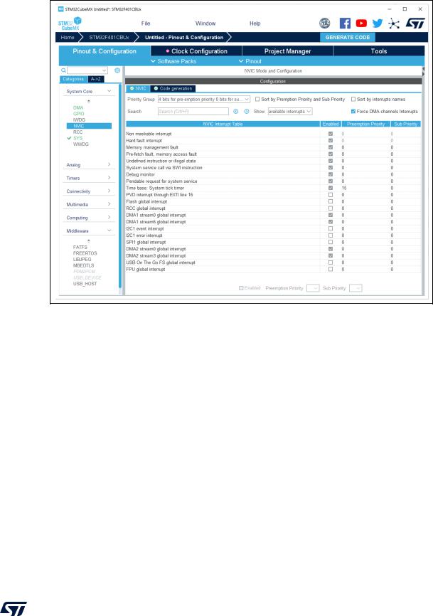
4.4.14NVIC configuration window
Click NVIC in the System view to open the Nested Vector interrupt controller configuration window (see Figure 69).
Interrupt unmasking and interrupt handlers are managed within two tabs:
•NVIC, to enable peripheral interrupts in the NVIC controller and to set their priorities
•Code generation, to select options for interrupt related code generation
Enabling interruptions using the NVIC tab view
The NVIC view (see Figure 69) does not show all possible interrupts, but only the ones available for the peripherals selected in the Pinout & Configuration panels. System interrupts are displayed but can never be disabled.
Check/uncheck the Show only enabled interrupts box to filter or not enabled interrupts.
When DMA channels are configured in the project, check/uncheck “Force DMA channels interrupts” to automatically enable/disable DMA channels interrupts in the generated code.
Use the search field to filter out the interrupt vector table according to a string value. As an example, after enabling UART peripherals from the Pinout panel, type UART in the NVIC search field and click the green arrow close to it: all UART interrupts are displayed.
Enabling a peripheral interrupt generates NVIC function calls HAL_NVIC_SetPriority and HAL_NVIC_EnableIRQ for this peripheral.
96/453 |
UM1718 Rev 41 |
UM1718 |
STM32CubeMX user interface |
|
|
Figure 69. NVIC configuration tab - FreeRTOS disabled
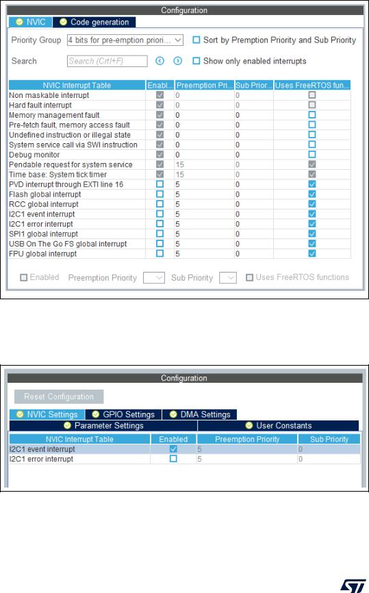
When FreeRTOS is enabled, an additional column is shown (see Figure 70).
In this case, all the interrupt service routines (ISRs) that are calling the interrupt safe FreeRTOS APIs must have a priority lower than the priority defined in the LIBRARY_MAX_SYSCALL_INTERRUPT_PRIORITY parameter (the highest the value, the lowest the priority). The check in the corresponding checkbox guarantees that the restriction is applied.
If an ISR does not use such functions, the checkbox can be unchecked and any priority level can be set. It is possible to check/uncheck multiple rows (see rows highlighted in blue in
Figure 70).
UM1718 Rev 41 |
97/453 |
STM32CubeMX user interface |
UM1718 |
|
|
Figure 70. NVIC configuration tab - FreeRTOS enabled
Peripheral dedicated interrupts can also be accessed through the NVIC window in the configuration window (see Figure 71).
Figure 71. I2C NVIC configuration window
98/453 |
UM1718 Rev 41 |

UM1718 |
STM32CubeMX user interface |
|
|
STM32CubeMX NVIC configuration consists in selecting a priority group, enabling/disabling interrupts and configuring interrupts priority levels (preemption and sub-priority levels):
1.Select a priority group
Several bits allow to define NVIC priority levels. These bits are divided in two priority groups corresponding to two priority types: preemption priority and sub-priority. For example, in the case of STM32F4 MCUs, the NVIC priority group 0 corresponds to 0-bit preemption and 4-bit sub-priority.
2.In the interrupt table, click one or more rows to select one or more interrupt vectors. Use the widgets below the interrupt table to configure the vectors one by one or several at a time:
–Enable checkbox: check/uncheck to enable/disable the interrupt.
–Preemption priority: select a priority level. The preemption priority defines the ability of one interrupt to interrupt another.
–Sub-priority: select a priority level. The sub-priority defines the interrupt priority level.
Code generation options for interrupt handling
The Code Generation view allows customizing the code generated for interrupt initialization and interrupt handlers:
•Selection/Deselection of all interrupts for sequence ordering and IRQ handler code generation
Use the checkboxes in front of the column names to configure all interrupts at a time (see Figure 72). Note that system interrupts are not eligible for init sequence reordering as the software solution does not control it.
UM1718 Rev 41 |
99/453 |
STM32CubeMX user interface |
UM1718 |
|
|
Figure 72. NVIC Code generation – All interrupts enabled
•Default initialization sequence of interrupts
By default, the interrupts are enabled as part of the peripheral MSP initialization function, after the configuration of the GPIOs and the enabling of the peripheral clock.
This is shown in the CAN example below, where HAL_NVIC_SetPriority and HAL_NVIC_EnableIRQ functions are called within stm32xxx_hal_msp.c file inside the peripheral msp_init function.
Interrupt enabling code is shown in bold:
void HAL_CAN_MspInit(CAN_HandleTypeDef* hcan)
{
GPIO_InitTypeDef GPIO_InitStruct; if(hcan->Instance==CAN1)
{
/* Peripheral clock enable */ __CAN1_CLK_ENABLE();
/**CAN1 GPIO Configuration
PD0 |
------> CAN1_RX |
PD1 |
------> CAN1_TX |
*/ |
|
GPIO_InitStruct.Pin = GPIO_PIN_0|GPIO_PIN_1;
GPIO_InitStruct.Mode = GPIO_MODE_AF_PP;
100/453 |
UM1718 Rev 41 |
UM1718 |
STM32CubeMX user interface |
|
|
GPIO_InitStruct.Pull = GPIO_NOPULL;
GPIO_InitStruct.Speed = GPIO_SPEED_FREQ_VERY_HIGH;
GPIO_InitStruct.Alternate = GPIO_AF9_CAN1;
HAL_GPIO_Init(GPIOD, &GPIO_InitStruct);
/* Peripheral interrupt init */ HAL_NVIC_SetPriority(CAN1_TX_IRQn, 2, 2); HAL_NVIC_EnableIRQ(CAN1_TX_IRQn);
}
}
For EXTI GPIOs only, interrupts are enabled within the MX_GPIO_Init function:
/*Configure GPIO pin : MEMS_INT2_Pin */ GPIO_InitStruct.Pin = MEMS_INT2_Pin; GPIO_InitStruct.Mode = GPIO_MODE_EVT_RISING; GPIO_InitStruct.Pull = GPIO_NOPULL; HAL_GPIO_Init(MEMS_INT2_GPIO_Port, &GPIO_InitStruct);
/* EXTI interrupt init*/ HAL_NVIC_SetPriority(EXTI15_10_IRQn, 0, 0); HAL_NVIC_EnableIRQ(EXTI15_10_IRQn);
For some peripherals, the application still needs to call another function to actually activate the interruptions. Taking the timer peripheral as an example, the HAL_TIM_IC_Start_IT function needs to be called to start the Timer input capture (IC) measurement in interrupt mode.
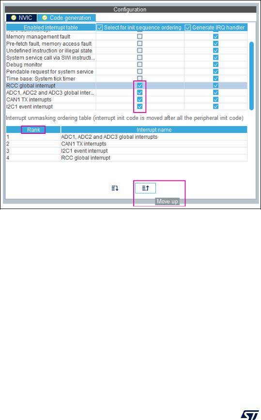
•Configuration of interrupts initialization sequence
Checking Select for Init sequence ordering for a set of peripherals moves the HAL_NVIC function calls for each peripheral to a same dedicated function, named MX_NVIC_Init, defined in the main.c. Moreover, the HAL_NVIC functions for each peripheral are called in the order specified in the Code generation view bottom part (see Figure 73).
As an example, the configuration shown in Figure 73 generates the following code:
/** NVIC Configuration */
void MX_NVIC_Init(void)
{
/* CAN1_TX_IRQn interrupt configuration */ HAL_NVIC_SetPriority(CAN1_TX_IRQn, 2, 2); HAL_NVIC_EnableIRQ(CAN1_TX_IRQn);
/* PVD_IRQn interrupt configuration */ HAL_NVIC_SetPriority(PVD_IRQn, 0, 0); HAL_NVIC_EnableIRQ(PVD_IRQn);
/* FLASH_IRQn interrupt configuration */ HAL_NVIC_SetPriority(FLASH_IRQn, 0, 0); HAL_NVIC_EnableIRQ(CAN1_IRQn);
/* RCC_IRQn interrupt configuration */
UM1718 Rev 41 |
101/453 |
STM32CubeMX user interface |
UM1718 |
|
|
HAL_NVIC_SetPriority(RCC_IRQn, 0, 0);
HAL_NVIC_EnableIRQ(CAN1_IRQn);
/* ADC_IRQn interrupt configuration */ HAL_NVIC_SetPriority(ADC_IRQn, 0, 0); HAL_NVIC_EnableIRQ(ADC_IRQn);
}
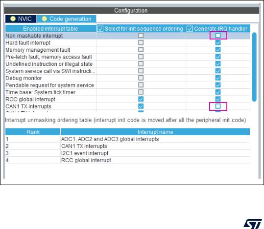
•Interrupts handler code generation
By default, STM32CubeMX generates interrupt handlers within the stm32xxx_it.c file. As an example:
void NMI_Handler(void)
{
HAL_RCC_NMI_IRQHandler();
}
void CAN1_TX_IRQHandler(void)
{
HAL_CAN_IRQHandler(&hcan1);
}
The column Generate IRQ Handler allows the user to control whether the interrupt handler function call can be generated or not. Deselecting CAN1_TX and NMI interrupts from the Generate IRQ Handler column as shown in Figure 73 removes the code mentioned earlier from the stm32xxx_it.c file.
Figure 73. NVIC Code generation – IRQ Handler generation
102/453 |
UM1718 Rev 41 |