
- •NI 5102 User Manual
- •Worldwide Technical Support and Product Information
- •National Instruments Corporate Headquarters
- •Worldwide Offices
- •Important Information
- •Warranty
- •Copyright
- •Trademarks
- •WARNING REGARDING USE OF NATIONAL INSTRUMENTS PRODUCTS
- •Contents
- •About This Manual
- •Conventions Used in This Manual
- •Related Documentation
- •About Your NI 5102
- •Acquiring Data with Your NI 5102
- •Interactively Controlling your NI 5102 with the Scope Soft Front Panel
- •NI-SCOPE Driver
- •NI Application Software
- •Using PXI with CompactPCI
- •Table 1-1. NI 5102 (PXI) J2 Pin Assignment
- •Optional Equipment
- •What You Need to Get Started
- •Unpacking
- •Installing the NI 5102
- •Table 2-1. NI 5102 (USB) LED Patterns
- •Hardware Configuration
- •Understanding Digitizers
- •Nyquist Theorem
- •Figure 3-1. Aliased Sine Wave When Waveform is Under Sampled
- •Analog Bandwidth
- •Figure 3-2. Analog Bandwidth
- •Sample Rate
- •Figure 3-3. 1 MHz Sine Wave Sample
- •Vertical Sensitivity
- •Figure 3-4. Transfer Function of a 3-Bit ADC
- •ADC Resolution
- •Record Length
- •Triggering Options
- •Making Accurate Measurements
- •Figure 3-5. Dynamic Range of an 8-Bit ADC with Three Different Gain Settings
- •Passive Probe
- •How to Compensate Your Probe
- •Figure 3-7. Connecting the Probe Compensation Cabling
- •Figure 3-8. Probe Compensation Comparison
- •Active and Current Probes
- •Figure 4-1. NI 5102 (PCI, PXI, ISA) Block Diagram
- •Figure 4-2. NI 5102 (PCMCIA, USB) Block Diagram
- •I/O Connector
- •Figure 4-3. NI 5102 (PCI, ISA) I/O Connectors
- •Figure 4-4. NI 5102 (PCMCIA) I/O Connectors
- •Figure 4-6. NI 5102 (PXI) I/O Connectors
- •Signal Connections
- •Table 4-1. I/O Connector Signal Descriptions
- •Serial Communications Port (AUX)
- •Analog Input
- •Table 4-3. AC/DC Coupling Change Settling Rates with NI Probes
- •ADC Pipeline Delay
- •Figure 4-7. Scan Clock Delay
- •Acquisition Modes
- •Posttrigger Acquisition
- •Table 4-4. Possible Number of Samples for Posttriggered Scans
- •Figure 4-8. Posttrigger Acquisition
- •Table 4-5. Posttrigger Acquisition Signals
- •Pretrigger Acquisition
- •Table 4-6. Possible Number of Samples for Pretriggered Mode
- •Figure 4-9. Pretrigger Acquisition
- •Table 4-7. Pretrigger Acquisition Signals
- •Trigger Sources
- •Figure 4-10. Scan Clock, Start Trigger, and Stop Trigger Signal Sources
- •Analog Trigger Circuit
- •Trigger Hold-off
- •Figure 4-11. Pretrigger and Posttrigger Acquisitions with Hold-off
- •Random Interleaved Sampling
- •Calibration
- •RTSI Bus Trigger and Clock Lines
- •Figure 4-12. RTSI Bus Trigger Lines
- •PFI Lines
- •PFI Lines as Inputs
- •PFI Lines as Outputs
- •Master/Slave Operation
- •Restrictions
- •Connecting Devices
- •Glossary
- •Numbers/Symbols
- •Index
Chapter 4 Hardware Overview
Analog Trigger Circuit
The NI 5102 contains a sophisticated analog trigger circuit that accepts boolean outputs from level comparators and makes intelligent decisions about the trigger. Several triggering modes are available, including edge, window, and hysteresis. For information on configuring trigger functions, see the Triggering Functions and Parameters section in Chapter 3, Common Functions and Examples, of your NI-SCOPE Software User Manual.
Trigger Hold-off
Trigger hold-off is the length of time that the NI 5102 waits after finishing an acquisition before it may accept another trigger. Hold-off is provided in hardware using a 24-bit down counter clocked by a 2.5 MHz internal timebase. With this configuration, you can select a hardware hold-off value of 800 ns to 6.71 s in increments of 400 ns.
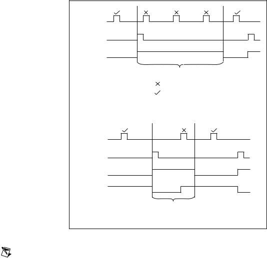
When an acquisition is in progress, the counter is loaded with a digital value that corresponds to the desired hold-off time. The End of Acquisition signal triggers the counter to start counting down. Before the counter reaches its terminal count (TC), all triggers are rejected in hardware. At TC, the hold-off counter reloads the hold-off value and prepares to accept the next trigger. Figure 4-11 shows a timing diagram of signals when hold-off is enabled.
© National Instruments Corporation |
4-15 |
NI 5102 User Manual |

Chapter 4 Hardware Overview
Start |
End of |
Acquisition |
Hold-off |
Hold-off Time in nanoseconds |
(Adjustable between 800 ns and 6.71 s) |
= Trigger Not Accepted |
= Trigger Accepted |
a. Posttriggered Acquisition with Hold-off |
Stop |
End of |
Acquisition |
Hold-off |
Acquisition |
in Progress |
Hold-off Time in nanoseconds |
(Adjustable between 800 ns and 6.71 s) |
b. Pretriggered Acquisition with Hold-off |
Figure 4-11. Pretrigger and Posttrigger Acquisitions with Hold-off
Note When you use trigger hold-off, you cannot calibrate your probe or generate an asynchronous frequency at the same time. The counter that is used to implement trigger hold-off also generates the probe calibration signal and the asynchronous pulse train.
NI 5102 User Manual |
4-16 |
ni.com |