
- •PROJECT BACKGROUND
- •PROJECT SCOPE
- •PROJECT DESIGN BASIS
- •Site Characteristics
- •Location
- •Topography
- •Transportation Access
- •Available Utilities
- •Site Ambient Conditions
- •Site Specific Design Considerations
- •Rainfall/Snowfall
- •Frost Penetration
- •Wind
- •Seismic Data
- •Flood Plain
- •Soil Conditions
- •Noise
- •Maintenance and Accessibility
- •Modularization Requirements
- •Fuel Feedstock and Flue Gas Characteristics
- •Power Plant Fuel Data
- •Flue Gas Conditions
- •PERMITTING PATHWAY
- •Air Permitting
- •Prevention of Significant Deterioration (PSD) Modeling Overview
- •Potentially Applicable Air Permitting Scenarios
- •Scenario 1: Carbon Capture Plant as a Single Source with PSGC
- •Scenario 2A: Carbon Capture Plant as a Separate Source with Only Emissions Created by the Carbon Capture Plant Subject to Permitting
- •Scenario 2B: Carbon Capture Plant as a Separate Source with ALL Emissions from Carbon Capture Plant Subject to Permitting
- •Air Permitting Strategy Recommendation
- •Water and Wastewater Permitting
- •Background
- •Makeup Water Permitting
- •Wastewater Permitting
- •Mechanical Draft Cooling Tower
- •Wastewater Treatment
- •BASIC CONTRACTING AND PURCHASING STRATEGY
- •Procurement Strategy
- •Engineering Interface
- •Vendor Quality Management
- •Long-Lead Procurement
- •ENGINEERING DESIGN PACKAGES
- •Process Engineering
- •Process Flow Diagrams
- •Heat Balance
- •HAZOP/PHA
- •PHA Process
- •Methodology
- •PHA Recommendations
- •Equipment List and Specifications
- •Cause and Effect Diagrams (six diagrams, pages 75-85)
- •Overpressure Relief Study
- •Introduction
- •Relief Philosophy
- •Evaluation Method
- •Civil Engineering
- •Geologic and Soil Load Assessment
- •Geotechnical Investigation
- •Subsurface Conditions
- •Frost Protection
- •Storm Water Runoff and Spill Containment Assessment
- •Structural Engineering
- •Mechanical Engineering
- •3D model and/or equipment elevation sections & plan drawings
- •Electrical Engineering
- •Electrical load lists
- •One-line diagram(s)
- •Instrumentation & Controls Engineering (System Integration)
- •Communications Infrastructure
- •Control Cabinet
- •Call Station
- •Bi-Directional Loudspeaker
- •Line Balance Assembly
- •Amplifiers
- •Horn and Driver Assemblies
- •Junction Boxes
- •Fire Protection Engineering
- •Authority Having Jurisdiction
- •Building and Fire Codes
- •Methodology
- •Occupancies
- •Fire Alarm System
- •Water Supply
- •Facilities Engineering
- •HVAC
- •General HVAC Design Criteria
- •Admin / Warehouse Building HVAC Design
- •Water Treatment Building HVAC Design
- •HVAC Design Standards / Reference
- •Site Security
- •Plant Layout and Construction Access
- •Constructability
- •Site Work
- •Site Preparation
- •Trenching and Excavation
- •Backfilling
- •Grading
- •Roads and Parking
- •Temporary Construction Trailers
- •Temporary Power
- •Temporary Water
- •Waste Disposal
- •Construction Stormwater Management
- •Lay-down Areas
- •Sequencing of construction work
- •Piping
- •Equipment
- •Pipe Rack Modularization (ISBL)
- •Project Cost Estimate (~ +/- 15%)
- •Project Cost of Capture
- •Calculating Cost of Capture
- •Cost of Capture Summary
- •Estimated Project Schedule

Wind
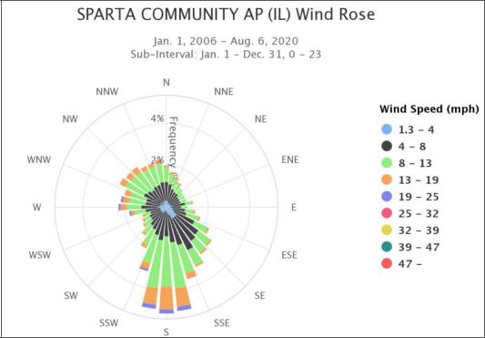
Figure 7. Sparta Community AP (IL) Wind Rose
Seismic Data
Table 4. Seismic Design Parameters
Risk Category |
Building Category III |
Seismic Importance Factor, Ie |
1.25 |
Spectral Response Acceleration |
|
Short Period, 0.2 Second, Ss |
0.57 g |
1-Second Period, S1 |
0.17 g |
Site Class |
C |
Design Spectral Response Acceleration Parameter |
|
Short Period, 0.2 Second, SDS |
0.58 g |
1-Second Period, SD1 |
0.20 g |
Seismic Design Category |
C |
Flood Plain
The effective FEMA Flood Insurance Rate Map (170997 0007 A) is dated December of 1980, prior to the original plant construction. Nearby areas of flooding due to a 100-year rainfall event include Mud Creek,
Page 15 of 145
which is located south of the existing plant: it is assumed that the plant property where new equipment will be designed is above of the 100-year base flood elevation.
Soil Conditions
Geotechnical investigation of the site was performed by Hanson Engineering Group Inc. (Hanson). The results of the investigation are contained in the final geotechnical report dated June 2021. Hanson’s geotechnical investigation included drilling 26 exploratory borings and installing three groundwater level monitoring wells. Bedrock was cored at selected boring locations. In addition, data from previous geotechnical investigations performed by MACTEC, Inc at the facility were reviewed.
Deep foundations will be utilized for the major site structures. Large structures with relatively light loading will be put on mat foundations. Removing and stockpiling the topsoil will be at Owner-designated area(s) for later reuse with Owner’s approval.
Noise
The system will be designed such that equipment noise levels in areas where access for operations and maintenance is required, whether on a continuous or intermittent basis, and external to the plant buildings, are of an acceptable level as follows:
•Equipment shall be specified such that the A-weighted sound level resulting from the operation of equipment (including drive motors) shall not exceed a free-field spatial arithmetic average (per piece of equipment) of 85 dBA along the equipment envelope at a height of 1.5 meters above the ground and personnel platforms. The equipment envelope is the perimeter line that completely encompasses the equipment package (including noise control devices) at a distance of 1 meter from the equipment face. Equipment that cannot satisfy the sound requirements will be acoustically insulated as necessary. If after insulating, equipment still cannot satisfy noise requirements, signage will be posted requiring hearing protection in effected area.
•Far field noise requirements are limited to stead state, base load operation. A far field noise study was performed by Hessler Associates, Inc., that provided the noise levels for nearby receptors.
Mitigation measures were also identified to comply with Illinois noise requirements.
Page 16 of 145