
- •PROJECT BACKGROUND
- •PROJECT SCOPE
- •PROJECT DESIGN BASIS
- •Site Characteristics
- •Location
- •Topography
- •Transportation Access
- •Available Utilities
- •Site Ambient Conditions
- •Site Specific Design Considerations
- •Rainfall/Snowfall
- •Frost Penetration
- •Wind
- •Seismic Data
- •Flood Plain
- •Soil Conditions
- •Noise
- •Maintenance and Accessibility
- •Modularization Requirements
- •Fuel Feedstock and Flue Gas Characteristics
- •Power Plant Fuel Data
- •Flue Gas Conditions
- •PERMITTING PATHWAY
- •Air Permitting
- •Prevention of Significant Deterioration (PSD) Modeling Overview
- •Potentially Applicable Air Permitting Scenarios
- •Scenario 1: Carbon Capture Plant as a Single Source with PSGC
- •Scenario 2A: Carbon Capture Plant as a Separate Source with Only Emissions Created by the Carbon Capture Plant Subject to Permitting
- •Scenario 2B: Carbon Capture Plant as a Separate Source with ALL Emissions from Carbon Capture Plant Subject to Permitting
- •Air Permitting Strategy Recommendation
- •Water and Wastewater Permitting
- •Background
- •Makeup Water Permitting
- •Wastewater Permitting
- •Mechanical Draft Cooling Tower
- •Wastewater Treatment
- •BASIC CONTRACTING AND PURCHASING STRATEGY
- •Procurement Strategy
- •Engineering Interface
- •Vendor Quality Management
- •Long-Lead Procurement
- •ENGINEERING DESIGN PACKAGES
- •Process Engineering
- •Process Flow Diagrams
- •Heat Balance
- •HAZOP/PHA
- •PHA Process
- •Methodology
- •PHA Recommendations
- •Equipment List and Specifications
- •Cause and Effect Diagrams (six diagrams, pages 75-85)
- •Overpressure Relief Study
- •Introduction
- •Relief Philosophy
- •Evaluation Method
- •Civil Engineering
- •Geologic and Soil Load Assessment
- •Geotechnical Investigation
- •Subsurface Conditions
- •Frost Protection
- •Storm Water Runoff and Spill Containment Assessment
- •Structural Engineering
- •Mechanical Engineering
- •3D model and/or equipment elevation sections & plan drawings
- •Electrical Engineering
- •Electrical load lists
- •One-line diagram(s)
- •Instrumentation & Controls Engineering (System Integration)
- •Communications Infrastructure
- •Control Cabinet
- •Call Station
- •Bi-Directional Loudspeaker
- •Line Balance Assembly
- •Amplifiers
- •Horn and Driver Assemblies
- •Junction Boxes
- •Fire Protection Engineering
- •Authority Having Jurisdiction
- •Building and Fire Codes
- •Methodology
- •Occupancies
- •Fire Alarm System
- •Water Supply
- •Facilities Engineering
- •HVAC
- •General HVAC Design Criteria
- •Admin / Warehouse Building HVAC Design
- •Water Treatment Building HVAC Design
- •HVAC Design Standards / Reference
- •Site Security
- •Plant Layout and Construction Access
- •Constructability
- •Site Work
- •Site Preparation
- •Trenching and Excavation
- •Backfilling
- •Grading
- •Roads and Parking
- •Temporary Construction Trailers
- •Temporary Power
- •Temporary Water
- •Waste Disposal
- •Construction Stormwater Management
- •Lay-down Areas
- •Sequencing of construction work
- •Piping
- •Equipment
- •Pipe Rack Modularization (ISBL)
- •Project Cost Estimate (~ +/- 15%)
- •Project Cost of Capture
- •Calculating Cost of Capture
- •Cost of Capture Summary
- •Estimated Project Schedule

Lay-down Areas
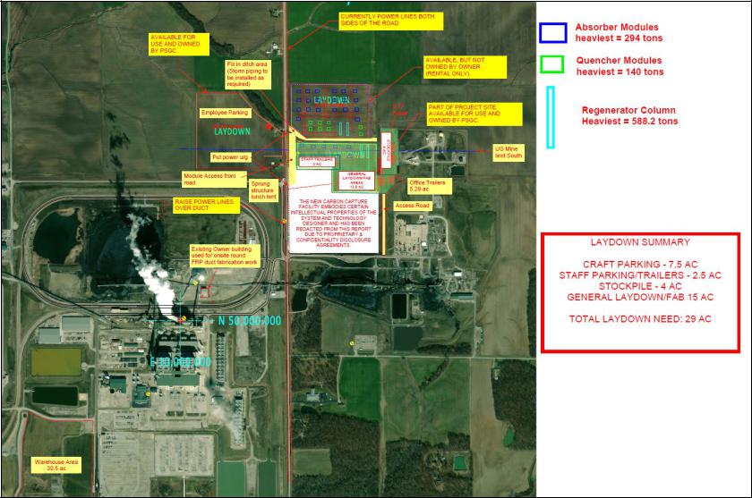
Figure 54. Construction Laydown Locations
Page 135 of 145
Construction laydown areas will be provided on the site proper as shown in Figure 54 – Construction Laydown Locations. These laydown areas will be used for storage, staging, parking, and miscellaneous equipment assembly tasks. The following summarizes the functional purpose of each Laydown Area.
•Laydown Area “A” – Reserved for construction parking, material storage, topsoil stock piling, and storage of small ancillary equipment.
•Laydown Area “B” – Reserved for short-term storage of sand, gravel, topsoil, and excavated material. This area will also be used for long term storage and pre-staging of large equipment and pipe rack modules. Of which, equipment will be “dressed” and preassembled with its shipped loose components to the greatest extent possible prior to installation. This will improve personnel safety by keeping as much work close to the ground as possible. Prior to the arrival of large pipe rack modules, the existing overhead transmission lines at the west property boundary between Laydown Area “B” and Highway 12 will need to be buried underground to achieve proper overhead clearances for equipment receiving.
•Laydown Area “C” – Reserved for short term construction material storage, topsoil stockpiling, and short-term storage of small ancillary equipment. Laydown Area “D” – Reserved for short term storage and final staging of large equipment, small ancillary equipment, and pipe rack modules. Area also used as primary site entrance access for construction vehicles. This area may be used to “dress” and pre-assemble equipment with its shipped loose components to the greatest extent possible prior to installation.
•Temporary Warehouse Laydown Yard – Small storage yard reserved for construction materials and
ancillary equipment that are fully assembled and do not require pre-staging work.
A temporary warehouse structure will be erected in the abandoned contractor parking lot area located west of the current contractor parking lot in the southwest corner of the existing power generation station’s campus. The temporary warehouse will be furnished with adequate climate control measures (where required), lights, telephone service, and broadband internet access for receiving and inventory control. The
Page 136 of 145