

Equipment List and Specifications
Table 14. ISBL Equipment List and Specifications
Item |
Service |
Specification / Type |
|
Number |
|||
|
|
||
D-001 |
Flue Gas Quencher |
Packed Tower |
|
D-002 |
CO2 Absorber |
Packed Tower |
|
D-003 |
Regenerator |
Packed Tower |
|
V-001 |
Regenerator Reflux Drum |
Vertical |
|
V-002 |
Steam Condensate Drum |
Vertical |
|
V-004 |
Reclaimer Steam Condensate Drum |
Vertical |
|
SU-001 |
Solution Sump Tank |
Flat Roof / Pit (Cylindrical) |
|
SU-002 |
Solution Storage Sump Tank |
Flat Roof / Pit (Cylindrical) |
|
T-001 |
Solution Storage Tank |
Cone Roof (Cylindrical) |
|
T-003 |
Caustic Soda Tank |
Cone Roof (Cylindrical) |
|
T-004 |
Reclaimed Waste Tank |
Cone Roof (Cylindrical) |
|
T-005 |
Wash Water Storage Tank |
Cone Roof (Cylindrical) |
|
T-007 |
Fresh Solution Storage Tank |
Cone Roof (Cylindrical) |
|
U-001 |
Filtration Tank |
Filter |
|
F-002 |
Down Stream Guard Tank |
Filter |
|
F-003 |
Solution Sump Filter |
Filter |
|
F-005 |
Solution Storage Sump Filter |
Filter |
|
E-001 |
Flue Gas Cooling Water Cooler |
Plate Type |
|
E-002 |
Wash Water Cooler |
Plate Type |
|
E-003 |
Solution Heat Exchanger |
Plate Type |
|
E-005 |
Regenerator Reboiler |
Shell and Tube Type |
|
E-006 |
Lean Solution Cooler |
Plate Type |
|
E-007 |
Reclaimer Heater |
Shell and Tube Type |
|
FA-001 |
Flue Gas Blower |
Blower |
|
P-001 |
Flue Gas Cooling Water Pump |
Centrifugal Pump |
|
P-002 |
Wash Water Circulation Pump |
Centrifugal Pump |
|
P-003 |
Rich Solution Pump |
Centrifugal Pump |
|
P-004 |
Regenerator Reflux Pump |
Centrifugal Pump |
|
P-005 |
Lean Solution Pump |
Centrifugal Pump |
|
P-006 |
Solution Pump |
Centrifugal Pump |
|
P-008 |
Steam Condensate Return Pump |
Centrifugal Pump |
|
P-010 |
Reclaimer Caustic Soda Feed Pump |
Diaphragm Pump |
|
P-011 |
Reclaimed Waste Pump |
Rotary Pump |
|
P-014 |
Reclaimer Steam Condensate Return |
Centrifugal Pump |
|
|
Pump |
|
|
P-020 |
Caustic Soda Make-up Pump |
Diaphragm Pump |
|
P-027 |
Solution Storage Sump Pump |
Centrifugal Pump |
|
K-101 |
CO2 Compressor |
Geared Compressor |
Page 73 of 145
KT-101 |
CO2 |
Compressor Steam Turbine |
Steam Turbine |
V-101 |
1st Stage Suction Scrubber |
Vertical |
|
E-102 |
Final Stage Discharge Cooler |
Shell and Tube Type |
|
U-101 |
CO2 |
Dehydration Unit |
TEG System |
Page 74 of 145
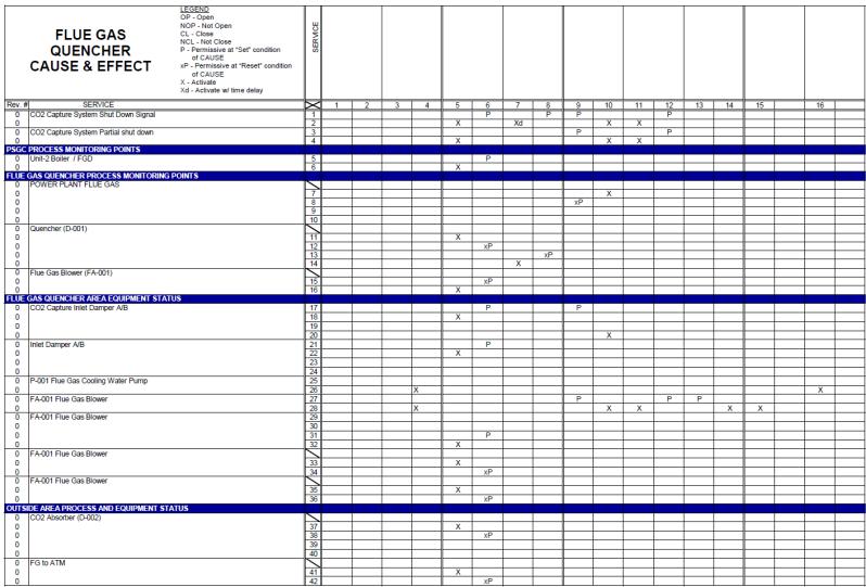
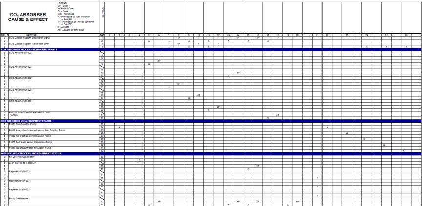
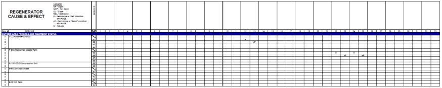
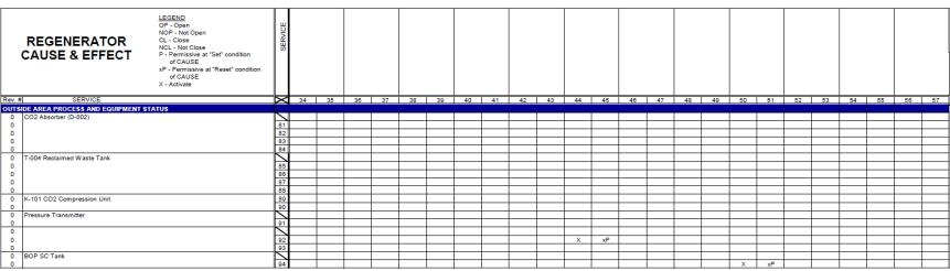
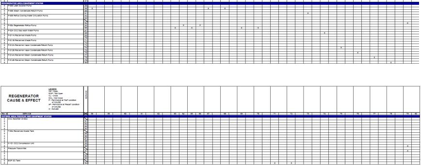
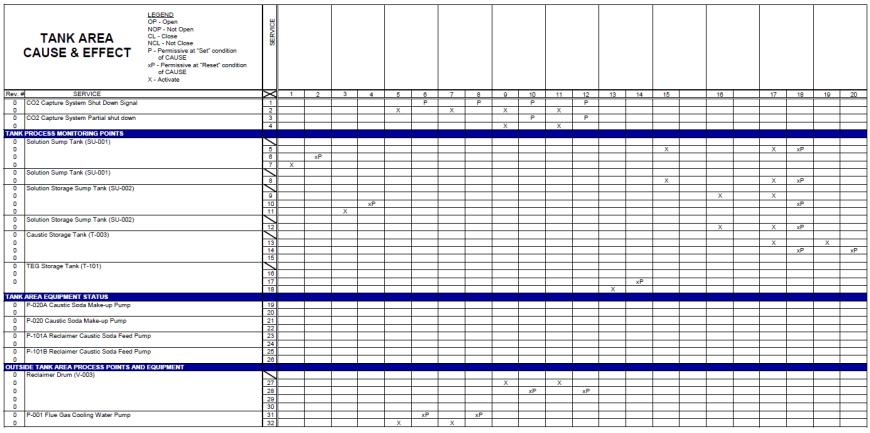
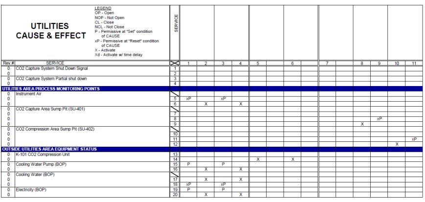
Cause and Effect Diagrams (six diagrams, pages 75-85)
Page 75 of 145
Page 76 of 145

Page 77 of 145
Page 78 of 145

Page 79 of 145
Page 80 of 145
Page 81 of 145
Page 82 of 145
Page 83 of 145

Page 84 of 145
Page 85 of 145