

01 POWER ISLAND / 04 CO2 capture / Compostilla-project-OXYCFB300-FEED-report
.pdf30 | |
OXYCFB300 COMPOSTILLA. CARBON CAPTURE AND STORAGE DEMOSTRATION PROJECT |
2.3 PROJECT ORGANIZATION |
|
2.3.1 Action Detailed |
2.3.2 Action Implementation |
The Project ¡s organized ¡n seven work packages (WP): |
|
WP0: “Coordination and management”. |
Management structure and procedures |
WP1: “CO2 Capture”. |
The regulation of the management of the Action, financial ar- |
WP2: “CO2 Transport”. |
rangements and partners’ rights and obligations are the contents |
WP3: “CO2 Storage”. |
of the agreements completed and to be completed among the |
WP4: “Permitting”. |
Beneficiaries. |
WP5: “Public perception”. |
|
WP6: “Knowledge sharing”. |
The management framework is shown below: |
STEERING COMMITTEE
Coordinator (ENDESA): Martín Madrid
ENDESA: Martín Madrid, Eduardo Santos
CIUDEN: Vicente Cortés, Modesto Montoto
FW: Arto Hotta, Antonio Castilla
European Commission
WP0
Coordinator (ENDESA): Ramón Fdez
Economic Financial Team (EFT) |
Project Management Team (PMT) |
Social Acceptance Team (WP5) |
Coordinator (ENDESA): Ramón Fdez |
Coordinator (ENDESA): P. Gutiérrez |
Coordinator (CIUDEN): M. Lupión |
ENDESA: P. Gutiérrez |
ENDESA: Ramón Fdez |
ENDESA: R. Cortés |
CIUDEN: B. Navarrete |
CIUDEN: B. Navarrete |
CIUDEN: M. Lupión |
FW: Satu Antikainen |
FW: T. Ollikainen |
|
Task 11 |
Task 12 |
Task 13 |
Task 14 |
Task 15 |
Task 16 |
Task 17 |
Task 21 |
Task 22 |
Task 23 |
Task 24 |
|
|
|
|
|
|
|
|
|
|
Task 31 |
Task 32 |
Task 33 |
Task 34 |
Task 35 |
Task 36 |
|
Task 41 |
Task 42 |
Task 43 |
Task 44 |
|
|
|
|
|
|
|
|
|
|
Task 61 |
Task 62 |
Task 63 |
Task 64 |
Task 65 |
|
|
|
|
|
|
|
|
|
Task 51
Task 52
Task 53
Task 54
Task 55
Task 56
Figure 2.4 Management structure (as agreed between the Partners at the beginning of the Action)
The Steering Committee is responsible for the Beneficiaries strategy and leadership. The Steering Committee is formed by representatives of the three Beneficiaries.The coordination is responsibility of ENDESA.
The Coordinator is responsible for maintaining an overview of the Action and supervisory role in order to guarantee the conformation between the contract, technical contributions and final results. The Coordinator manages the implementation of the Action
according to the directions and decisions delivered by the Steering Committee. The Coordinator consolidates the Action planning, progress reports, and budgetary overviews, as well as, coordinates the communication among workpackages. Two supporting teams help to the Coordinator in these activities: a planning and management team, and an economical and financial team. The Coordinator also assures the relations and contacts with the European Commission.
CHAPTER 2. OXYCFB300 FRAMEWORK |
| 31 |
Monitoring and verification procedures
In order to manage the Action and ensure the final objectives and the adequate quality of the work, continuous monitoring has been carried out. Periodically, Steering Committee official meetings have been held all along the action to manage the Project. Other Project teams, including the Project Management Team and the Economical and Financial Team met frequently for coordinating the action. Specific purposed technical meetings between the partners were also held in the close-up range.
The Beneficiaries produced different reports throughout Action’s life. These reports were used by the Steering Committee to take
decisions about the Action and supply recommendations to WP leaders.
Activity technical reports have been generated every six months and reported to the European Community. Management and financial reports were generated every twelve months and also reported to the European Community, including the explanation of the use of the resources, the financial statements with the costs incurred by the three partners and a summary financial report and audited costs certificates.
3.1 |
FEED Organization . . . . . . . . . . . . . . . . . . . . . . . . . . . . . . . . . . . . . . . . . . . . . . . . . . . . . . . . . . . . . . . . . |
35 |
Access to and use of the information ¡n this document ¡s subject to the terms of the important notice at the front of the document

3
FEED Project Management

34 | |
OXYCFB300 COMPOSTILLA. CARBON CAPTURE AND STORAGE DEMOSTRATION PROJECT |
Index |
|
|
3.1 |
FEED Organization . . . . . . . . . . . . . . . . . . . . . . . . . . . . . . . . . . . . . . . . . . . . . . . . . . . . . . . . . . . . . . |
35 |
|
3.1.1 Technology Development Stage: FEED Objectives . . . . . . . . . . . . . . . . . . . . . . . . . . . . . |
35 |
|
3.1.2 Development Organization FEED . . . . . . . . . . . . . . . . . . . . . . . . . . . . . . . . . . . . . . . . . . . . |
36 |
|
3.1.3 FEED Project Management. . . . . . . . . . . . . . . . . . . . . . . . . . . . . . . . . . . . . . . . . . . . . . . . . . |
37 |
|
3.1.4 FEED Programme . . . . . . . . . . . . . . . . . . . . . . . . . . . . . . . . . . . . . . . . . . . . . . . . . . . . . . . . . . |
37 |
List of Figures
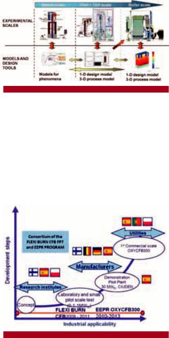
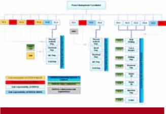
Figure 3.1 Technological development phases. . . . . . . . . . . . . . . . . . . . . . . . . . . . . . . . . . . . . . . . . . . . . . . . 35 Figure 3.2 Road Map for OXYCFB300 Project.. . . . . . . . . . . . . . . . . . . . . . . . . . . . . . . . . . . . . . . . . . . . . . . . 35 Figure 3.3 Task distribution. . . . . . . . . . . . . . . . . . . . . . . . . . . . . . . . . . . . . . . . . . . . . . . . . . . . . . . . . . . . . . . . . 36 Figure 3.4 Capture, transport and storage.. . . . . . . . . . . . . . . . . . . . . . . . . . . . . . . . . . . . . . . . . . . . . . . . . . . 37 Figure 3.5 Results and input data to the final decision making (conceptual).. . . . . . . . . . . . . . . . . . . . . 37
List of Tables
Table 3.1 Delays mitigation measures taken. . . . . . . . . . . . . . . . . . . . . . . . . . . . . . . . . . . . . . . . . . . . . . . . . 41 Table 3.2 Original planned dates and actual dates. . . . . . . . . . . . . . . . . . . . . . . . . . . . . . . . . . . . . . . . . . . . 42 Table 3.3 Floating tasks. . . . . . . . . . . . . . . . . . . . . . . . . . . . . . . . . . . . . . . . . . . . . . . . . . . . . . . . . . . . . . . . . . . 42
CHAPTER 3. FEED PROJECT MANAGEMENT
3.1 FEED ORGANIZATION
3.1.1 Technology Development Stage: FEED Objectives
Before the widespread deployment of a technology on a commercial scale, it must be subjected to different stages of escalation. Thus, it is checked and validated the process from a lower level to a higher level of development, evaluating in this escalation the potential deployment at higher levels. When results meet the expected requirements, they will be used to implement design improvements in the next stage, reducing the technical risk and economic investment, being otherwise the next inversion stage abandoned.
Figure 3.1 Technological development phases.
Thus, the scaling stages of the OXYCFB300 Project are: Laboratory scale: where it is studied: the combustion, flue gas composition, ash and slag produced, with different ranges of coals, oxidants and limestone.
Pilot Scale: Simulates at small-scale one electricity production plant, with the main equipment that would be implemented in the demo powerplant. This plant allows a detailed analysis of the different ways of operation and yields obtained.
Construction commercial demonstration plant, where electricity is generated for sale to commercial size.The trial period will be longer than a mature technology, but it will be made compatible in its final stages with the starting of the commercial operation of the Plant.
Figure 3.2 Road Map for OXYCFB300 Project.
| 35
To minimize the risks of the project it has been divided into two stages: the first one for the technology development and a second stage for the construction of the CCS commercial demonstration plant.
The CFB technology has been commercially demonstrated for conventional air firing but additional efforts to ensure the technological applicability to oxyfiring were required. For this purpose and within the framework of a powerful collaboration between the three partners of the project, an integrated Technological Development Plant (TDP) was constructed by CIUDEN during the EEPR program. This plant incorporates as the core unit a CFB boiler with the same technology of the future commercial demo plant, and at the same location where the OXY-CFB-300 capture plant is planned to be built.
Before the Decision Making (FID) about the construction of commercial demonstration project (Phase II), it was necessary to complete in this technological development phase (Stage I), all studies and works carried out in the three areas of capture, transport and storage, as well as all the necessary permits for the construction of the demonstration plant.
The description of the work committed to the EC under the program EEPR for Phase I of the Project Compostilla OXYCFB300 is defined in the document DOW Grant Agreement with the CE, Description of Works) and have been divided into different tasks and Deliverables.
The aims of the FEED work have been:
Analysis of state-of-the-art in CCS technologies, in the three areas: capture (oxyfuel technology in CFB boiler, air separation equipment and CO2 purification and compression), transport (singular transport studies of anthropogenic CO2) and injection and storage of CO2. Comparison of the available options in the market, mature enough to enable its commercial deployment with the required reliability. Study of the pros and cons, comparisons of performance, fuel consumption and costs, to define the best technical and economical solution to be developed in the FEED.
Performing of feasibility studies and analysis of the available design options. Development of conceptual and basic engineering through a work of successive approximations and iterations and considering all the constraints of the project.
Overall analysis of the project issues; identification of the main needs, environmental constraints and legal requirements; identification of dependencies and integration of the three areas (cap- ture-transport-storage).
Once technologies and major equipment have been selected, based on them and for each area separately (capture, transport and storage), the corresponding FEEDs have been developed detailed enough to obtain an economic estimate with a deviation of 10%. During the FEED design the following works have been made: mass and energy balances of the plant, water balances, flow diagrams and PI & Ds, description of major systems, study and optimization of layouts, load analysis and taking civil measurements,
36 | |
OXYCFB300 COMPOSTILLA. CARBON CAPTURE AND STORAGE DEMOSTRATION PROJECT |
single-wire schemes, study of the control architecture definition and design of the pipeline layout from the CO2 emission and capture point to final storage, valve arrangement, injection engineering development and monitoring of wells for CO2 final storage.
The development of the engineering has enabled the development of the documentation for permit applications and analysis of operational risks using HAZID (Hazard Identification), HAZOP (Hazard and Operational Risks) and QRA (Quantitative Risk Analysis).
Preparation of technical specifications to obtain quotations and carrying out the OXYCFB300 commercial demonstration plant budget with a deviation of 10%.
These quotations have been used, in addition to obtaining the commercial quotation and budget preparation, to gather additional technical information that would allow to progress in the developed FEED detail engineering. In case that FID is positive, the implementation phase of the commercial demonstration plant (Phase II) will be commenced.
3.1.2 Development Organization FEED
FEED engineering has been developed by ENDESA in collaboration with its partners in the project, based on their knowledge as power generation company and feasibility studies prior EEPR that were conducted with FOSTER WHEELER for Compostilla Project OXYCFB300.
During 2010-2013 ENDESA carried out Tasks related with FEED (Front-End Engineering Design) studies, involving suppliers and manufacturers during the design stage, in order to evaluate the technical, commercial and economical feasibility of the plant.
Figure 3.3 Task distribution.
Capture
TECNICAS REUNIDAS has provided support to ENDESA in the preparation of FEED engineering services for the 340 MW capture power plant. The design of the capture plant is conditioned by the requirements of the CFB boiler. Starting from the CFB boiler conceptual and basic engineering provided by FOSTER WHEELER and continuing with the CFB boiler FEED design developed in detail by FOSTER WHEELER, TÉCNICAS REUNIDAS together with ENDESA
have developed thermal cycle engineering and integration with other equipment and capture plant components.
ASU and CPU are not usually present in conventional thermal power plants, and had to be developed as “first of a kind” on this scale for OXYCFB300 plant, especially the CPU. Being very specific technologies in commercial development phase, it was necessary for major advance and detail of FEED work, hiring FEED engineering to appropriate technologists to develop CPU and ASU.
The activities related to the technological development of the boiler, ASU and CPU have been developed and partially financed by the European Framework Programme FP7 (FLEXI BURN), coordinated by VTT and ENDESA, FOSTER WHEELER and CIUDEN as major partners.
In a first stage, the necessary inputs for the design of plants have been provided to technologists, so by these means a first conceptual design has been obtained. The first conceptual design gave a way to the next stage of integration and optimization with the rest of the plant and FEED design of all systems and equipment. Comprenhensive Requests For Quotation were released.
Thus, through successive approximations and iterations in consumption, performance, layout optimizations and improvements it has been achieved conceptual design of the plant composition and economic estimation with a deviation of less than 10%.
Transport
WORLEY PARSONS has supported ENDESA in transport FEED engineering, reviewing and updating singular studies made during this stage of technological development in collaboration with DNV: studies of materials and purity of CO2, hydraulic studies, dynamic and CO2 pipeline definite layout (HEYMO engineering). Risk monitoring and safety studies have also been developed (CO2 leaks dispersion model).
Storage
WORLEY PARSONS has supported the team of experts and ENDESA`s Task Managers in carrying out the activities of Engineering, Front-End mode, Reservoir, Drilling, Injection engineering and Surface Facilities, in coordination with other project activities , for proper evaluation of the Zones described as sites under Geological Storage of Carbon Dioxide Bill. WP has been responsible for defining, specifying, selecting, planning, evaluating costs, timely delivery support, form and quality of the projects, contracts, services and campaigns associated with the Reservoir Engineering by third parties as SCHLUMBERGUER, WEATHERFORD, GEOSTOCK GESSAL, Halliburton and others in monitoring activities baseline surveys, 2D and 3D seismic, update static and dynamic models, magneto telluric campaigns and other tasks necessary for comprehensive evaluation of CO2 storage for the Project.
CHAPTER 3. FEED PROJECT MANAGEMENT |
| 37 |
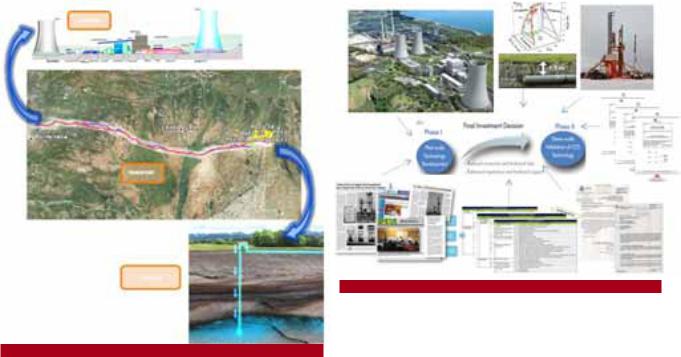
Figure 3.4 Capture, transport and storage.
3.1.3 FEED Project Management
During the development phase of the technology several activities had to be performed in parallel to the FEED design, as some inputs or requirements provided the necessary results to develop new tasks needed for defining this phase and achieving the targets set in EEPR.
Tasks such as regular consultation meetings throughout the project with different administrations, development of documentation for obtaining permits, preparing information for public perception activities and dissemination of knowledge, implementation and support internal and external audits, various commercial work and organization of requests for proposals, establishment of partnership agreements and confidentiality agreements with technologists and definition activities to define legislative, regulatory and operational framework of Business Development Plant have required the participation of experts and coordinators of the various tasks that form the FEED.
Within the works developed in parallel to FEED engineering design is the Integral Risk Assessment for Compostilla Project OXYCFB300 supporting Final Investment Decision of Phase 2 of the project (construction plant CCS capture, transport and storage deep geologic CO2 generated by a 340 MW oxyfuel plant).
Risk assessment as described in the description of works document (DOW), is an evaluation “complete and detailed” of risks “technological, financial, economic, regulatory, permitting, and social acceptance in relation to the investment decision to make “, so it is considered the ultimate result of the FEED work.
Figure 3.5 Results and input data to the final decision making (conceptual).
Endesa contracted DELOITTE consultant in October 2011 to develop specialized services to support the Integral Risk Assessment of Compostilla Project OXYCFB300, including market risk, business and regulatory risks, operational and integration risks (environmental, safety and health, quality and deadline).
These Works have taken as input technical risk studies (HAZID, HAZOP, QRA) developed by FEED engineering, as well as financial information that would enable ENDESA to develop the project.
Regarding social acceptance and public perception inputs, the project has carried out 4 major public engagement studies.
Social perception of qualitative study in Hontomín (July, 2011) Compostilla project public perception study (February, 2012) CO2 Storage Technologies Social acceptance in Sahagún (June, 2012)
Psychosocial study (June, 2012)
Since the completion of the above mention studies, the project had continued participating in in local fairs and new informative meetings with town-halls. A specific section on the website dedicated to Sahagún social acceptance campaign is still active at the project website www.compostillaproject.eu
3.1.4 FEED Programme
Tasks Identification and General Description
After signature of the Grant Agreement with the European Commission in May 2010 and finishing all the Project Structure and Work Breakdown Structure in coordination with the Partners, in June 2010 Endesa proceeded to organize and develop FEED activities for the 3 main Workpackages comprised in the Description of Work.

38 | |
OXYCFB300 COMPOSTILLA. CARBON CAPTURE AND STORAGE DEMOSTRATION PROJECT |
Front-End Engineering Design plans were arranged for Workpackage 1 CO2 Capture Task 1.7 “FEED”, Workpackage 2 CO2 Transport Task 2.4 “Engineering Bidding Process”, and Workpackage 3 CO2
Storage Task 3.3 “Extensive Subsurface Characterization”. Therefore, the date of June 2010 is internally considered as the Starting Point (SP) milestone for the FEED implementation at capture, transport and storage areas of the Oxycfb300 Compostilla project. Since then, FEED activities took along over the years 2010, 2011, 2012 and roughly half 2013. Once finished FEED activities of all Workpackages, the Close Out milestone has been reached by the date.
Accordingly, as depicted above, the FEED schedule has been run in between the following dates:
FEED Starting Point (SP): June 2010
FEED Close Out (CO): June 2013 (partial close outs: for capture November 2012, for transport January 2013 and for Storage June 2013)
FEED Performed Period: 36 months.
Baseline FEED schedules were defined and settled in June 2010, with the aim of accomplishing all the milestones in time for FID process start in June 2012. Several setbacks delayed gradually the Close Out milestone and thus the FID process start (for further detail see Critical Path). Performed actual FEED Programme (with real delays) is presented in this section.
Capture FEED Tasks
Capture FEED schedule was initially divided in two main blocks: CFB boiler FEED (primarly driven by FWEOy) and integration engineering FEED (primarly driven by Endesa). Both schedules had several links that were managed in common between Partners. In addition to this, CFB boiler FEED had vast connections with the test plan at Lagizsa plant, Canmet center and CIUDEN’s capture TDP1 facilities. Therefore, many activities performed in testing campaigns at the various facilities created a cascade of dependencies, in first degree by CFB boiler FEED and in second degree by the integration engineering FEED. In other words, any delay of the test plan had potential for relevant impacts on capture FEED schedule, especially if the CFB boiler design would have had suffered of major modifications due to tests results, which has not ocurred.
CFB boiler FEED activities started in June 2010 with the plant concept verification, standards and rules verification, and information for boiler design basis completion. Preliminary boiler design was completed by 1st quarter of 2011. After Canmet tests completion in late 2010 and definitive results, the boiler water – steam circuitry was partially updated in July 2011, in seek for higher efficiency and operational failures improvement. Also in July 2011, a preliminary
1 Technological Development Plant
version of the boiler PDMS 3D2 model was issued. In February 2012, based on material studies, the re-heaters materials were upgraded. During 2011 and 2012, boiler island engineering was done to the extent deemed necessary for achieving the targets of the FEED, including layout and piping engineering, performance engineering, systems engineering, strength engineering, electrical & control engineering, construction engineering, commissioning engineering, technical specifications, materials lists, civil and HVAC engineering. Also a dynamic model of the boiler was developed, operational requirements were discussed and safety studies were handled (HAZOP/HAZID studies). In spite of all these works, finalizing of the CFB boiler FEED and boiler design verification was subject to completion of CIUDEN TDP oxycombustion tests and analysis of results, in early 2013.
Regarding integration engineering FEED, after planning and purchasing services, and once requirements were defined from first boiler design steps, kick-off was held in October 2010. Integration engineering works were divided in two stages: preFEED and FEED. PreFEED took from October 2010 to May 2011, finalizing with the preliminary technical specifications of the main packages (ASU, CPU, boiler island and turbine island). PreFEED stage focused on heat & mass balances iteration process, aiming to integrate boiler balances with turbine balances in order to define accurately the steam-water cycle. Basic engineering documents (inc. preliminary layouts, landscape & architectural studies, preliminary environmental studies, topography and geotechnical studies, preliminary lists of loads and equipment or preliminary battery limts) were developed also during the PreFEED.
Once PreFEED finished, in May 2011 a budgetary RFQ3 to ASU, CPU, Power Island and Cooling Tower technologists was initiated, with the aim to obtain enough information to develop ASU & CPU integration (Task 1.3 “ASU & CPU technology development”). After several clarification meetings between Endesa, FWEOy and ASU/ CPU technologists, by September 2011 it turned out that all the information available was insufficient. Then a new RFQ was started, but with the aim to purchase ASU & CPU engineering services from technologists. By January 2012, ASU FEED and CPU FEED were kicked-off. Both FEEDs boosted up ASU & CPU integration activities, thus allowing during early 2012 to develop new heat & mass balances for the whole plant and auxiliary systems (in both MCR4 and partial loads, and in air and oxy modes). The new heat & mass balances comprised the updated boiler FEED design, turbine island balances from suppliers and tailor-made balances from the ASU & CPU FEED. Also during the ASU & CPU FEED, detail engineering, PDMS 3D models, safety studies, dynamic models, final specifications and investment estimates for ASU & CPU were developed.
2 Plant Design Management System three dimensional model
3Request For Quotation
4Maximus Continuous Rating

CHAPTER 3. FEED PROJECT MANAGEMENT |
| 39 |
During the 2nd half of 2011 and 1st half of 2012 detailed engineering of the integration FEED continued to all its extent, covering all the systems and areas of the future demo plant:
Regarding process engineering, performance was updated and P&ID5 diagrams and functional descriptions were issued for all systems. Water balances and auxiliary services balances were completed.
Regarding mechanical engineering, general arrangements were developed for all indoor and outdoor areas and floors, and piping isometrics were developed for 8 inches or bigger pipes. BOP6 equipment, pumps, fire fighting system, heat and ventilation systems, auxiliary fuel system, cooling tower internals, solids handling, ducts, pipes, package plants and other equipment were calculated and defined.
Layout of capture plant was completed. Architectural, civil and structural drawings of all buildings were done, and all main foundations were calculated. Cooling tower calculations were completed. Outdoor areas were defined and final landscape and architectural study was issued.
All the electrical single-wire diagrams were done for high voltage, medium voltage, duty current systems, safety voltage systems and uninterruptible power supply system; and typicals were developed for medium voltage. Grid calculations were developed for accurate definition of generator and main electrical equipment parameters.
Lightning, conduits and trays, transformers and cables (high, medium and low voltage), control cables, motors, motor control centers, cabinets, gas insulated substation and other electrical equipment were calculated and defined.
Control equipment, control architecture, control philosophy, instrumentation, valves, signals list and distributed control system requirements were defined.
Bill of materials and bill of quantities were issued for all systems and areas.
Health and safety studies were developed, including ATEX (explosive atmospheres), and HAZOP/HAZID studies for the whole capture plant.
Environmental impact study was completed as well as complementary studies (emissions study, noise study, waste production study and others).
Technical and procurement specifications for the 18 procurement packages defined were issued; including civil works, site preparation works, mechanical erection, electrical and control erection, detailed engineering, supervision and commissioning for the construction phase.
Once detail engineering completed, in June 2012 binding RFQ were launched. Evaluation of all bids was completed by September 2012,
5Piping and Instrumentation Diagram
6Balance of Plant
allowing by this means an accurate estimate of the capture demo plant investment, accounting market status to the date.
During the last few months of FEED study, dynamic model was also fully completed for the whole capture plant.
As a result of all the FEED studies, roughly 2.500 documents were issued and updated to the last version. This number indicates the size and extent of the FEED studies performed.
Transport FEED Tasks
Transport FEED studies were constrained by the development of transport singular studies, namely PreFEED activities in the transport FEED Programme.
Singular studies were developed during 2010 and 2011. Once defined the first preliminary traces and hydraulic studies, which was done in late 2010, all the singular studies were run in parallel, although some overlap between them was necessary for developing transportation concepts. The preliminary studies were also a significant deadline for the first environmental study (initial document), that was accomplished on time for the permitting process in March 2011. Research made on materials and impurities, which required laboratory testing, increased the initial period estimated for all the singular studies but in time for the extended deadline due to delays on CIUDEN’s transport TDP construction and testing, on the critical path. In parallel, dispersions models were adapted to the changes motivated by other studies. The only singular studies that continued during 2012 and beyond were the DNV’s initiative Pipetrans phase 2, in which Endesa participates only as an associate, but this activity was not critical at all and has only contributed to the project with the first preliminary conclusions.
Once singular studies finalized in late 2011, FEED studies were commenced in November 2011, including both CO2 pipeline and surface facilities at the location of injection. Basic design was updated as well as all the static and dynamic calculations. By November 2012, all the transport FEED was concluded, with all the detail engineering and the following main activities performed:
All the process engineering
All the main systems engineering
All the auxiliary systems engineering
Constructive project, including constructive method, materials, detailed layout drawings, list of affected land-owners and properties by the pipeline trace, crossings detailed drawings (rivers, roads, others)
Location and detail engineering of switchgear valves
Bill of quantities, bill of material and lists of all equipment, valves Monitoring, overpressure, crack arrestor, leak detection, corrosion protection, fire fighting and trap scrappers systems Environmental impact study including complementary studies (dispersion and leakage models)