

Ebooki / FREE_ENERGY_NIKOLA_TESLA_SECRETS_FOR_EVE
.pdfMODERN APPLICATION FOR SHORT-CIRCUITED COILS
By William Barbat
US Patent Application number 2007/0007844
Self-Sustaining Electric-Power Generator Utilizing Electrons of Low Inertial Mass to Magnify Inductive Energy
COMMENT In order to understand this device, you have to read Barbat’s patent application US 2007/0007844 A1: www.free-energy-info.com/PatD25.pdf
COMMENT I would like to point out that externally, it looks very much like Alfred Hubbard’s device.
81
AN EXAMPLE OF CASE 1
By Tariel Kapanadze
COMMENT: Adjust the positions of the coils to get the best result.
82
AN EXAMPLE OF CASE 1
By Steven Mark
TPU
REMARK: An idea – an asymmetrical transformer based on the shorted-circuited coil:
REMARK: The positions of the coils must be properly adjusted, in order to have no transmission feedback from the output to the input. To understand this better, read the part which is devoted to switchable inductance.
EXPLANATION:
83
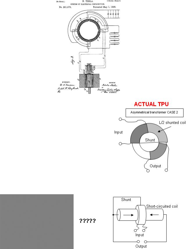
THE BASIS OF THE TPU
(Tesla Patent)
REMEMBER:
The position of the coils must be adjusted. The easiest way to do this is to add or remove turns at the ends of the coils.
AN EXAMPLE OF CASE 2
By Tariel Kapanadze
Mechanical device
84

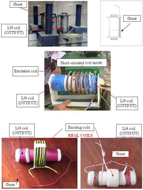
MODERN USE OF SHORT-CIRCUITED COILS by Cherepanov Valera (‘SR193’ in Russian forum)
COMMENT: This arrangement can be used for back-EMF suppression in resonance (spark excited) mode to get a laser effect (very exciting summation effects).
COMMENT: This was copied from this device of Tariel Kapanadze (???).
Don Smith
COMMENT: Mr. Tesla said: “The optimum relation for the main and additional coil is 3/4L and L/4”. Is that ratio used here?
COMMENT: If you don’t understand this schematic, look at simplest version of the coil.
85

THE SIMPLEST VERSION
where the output has zero influence on the input
Comment: This is an instance of case 1 where the output coil was removed, and some of the turns from the short-circuited coil were used instead.
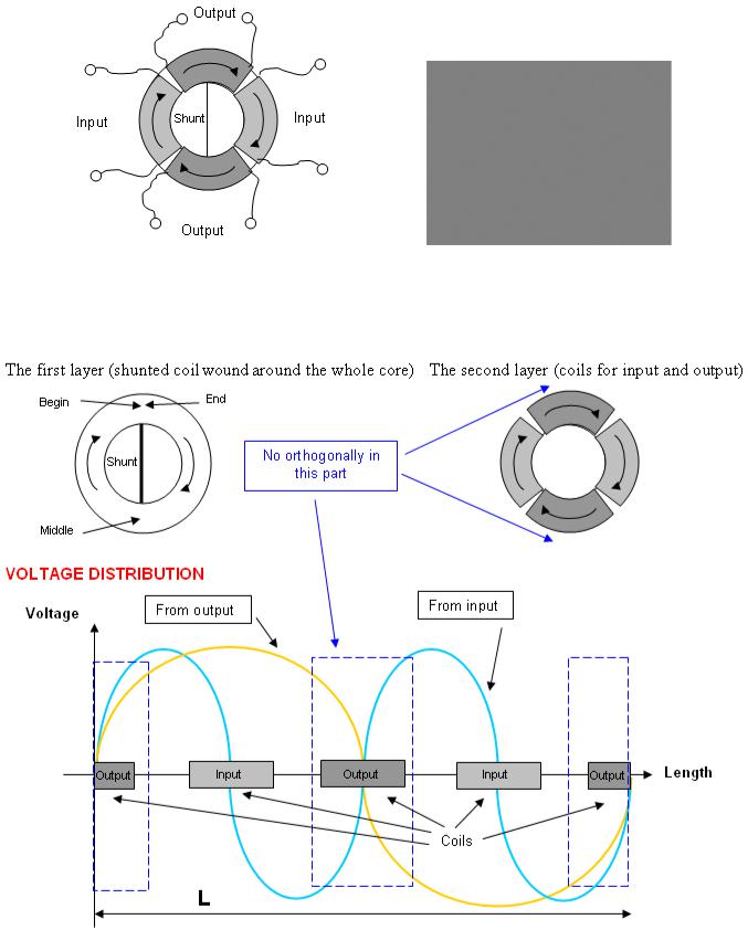
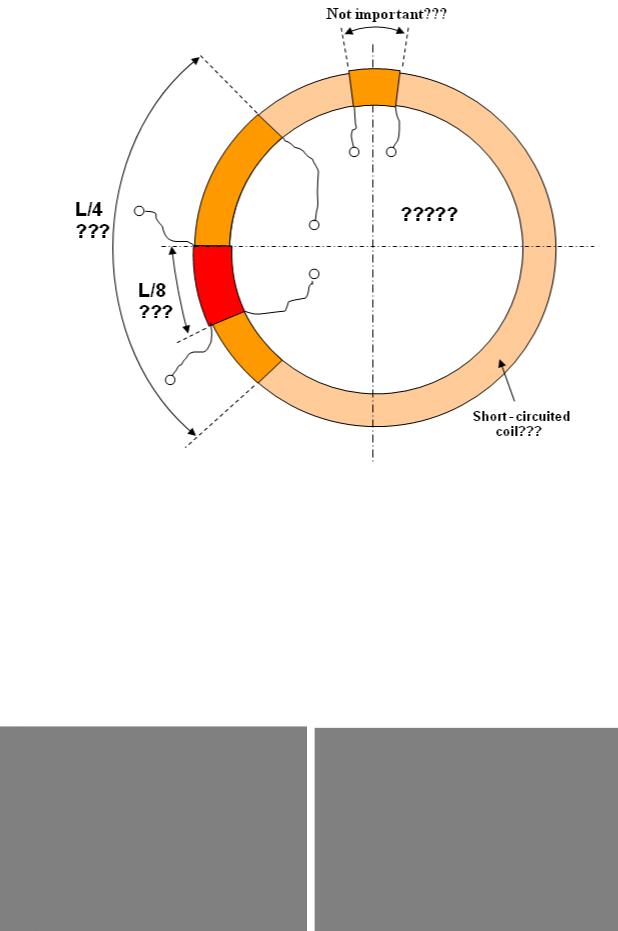
THE ASYMMETRICAL TRANSFORMER (BASED ON A SHORT-CIRCUITED COIL)
COMBINED WITH A STEP-DOWN TRANSFORMER?
Don Smith
86
THE RELATIONSHIPS of Don Smith’s TPU size and position are important.
REMARK: Those relationships are used to produce an asymmetrical transformer
MECHANICAL ANALOGUE OF THE
ASYMMETRICAL TRANSFORMER
CASE 2
By Don Smith
87
Schematic:
REMEMBER: Any asymmetrical transformer must be adjusted.
REMARK: Don Smith placed magnets inside the coils, but that is not important for understanding the process as his device does not match the schematic.
SOME REMARKS ON ASYMMETRICAL IN-FRONT CONNECTION
(Useful remarks)
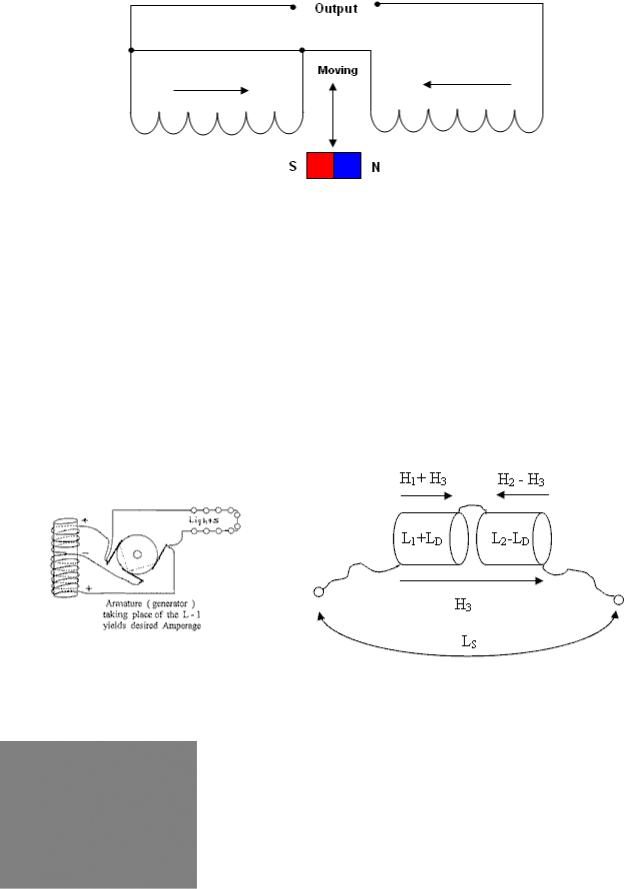
Some turns were added on one half of the coil, and some turns were removed from the other half. An additional magnetic field H3 was created, with inductance - LD.
RESULT: A large part of the total inductance acts as an inductor, and a small part acts as a capacitor. This is a well known fact (read books). The total voltage on the coil is less than on it’s halves.
Yellow – The voltage on the total coil
Red – The voltage on the large section of that coil
RESULT: The voltage on it’s halves is 4 times the voltage on the total coil
The measurements were made in the frequency band 10 kHz to 100 kHz.
88
Here is the result of a capacitor discharging into this coil:
SECRET 4
CURRENT AMPLIFICATION
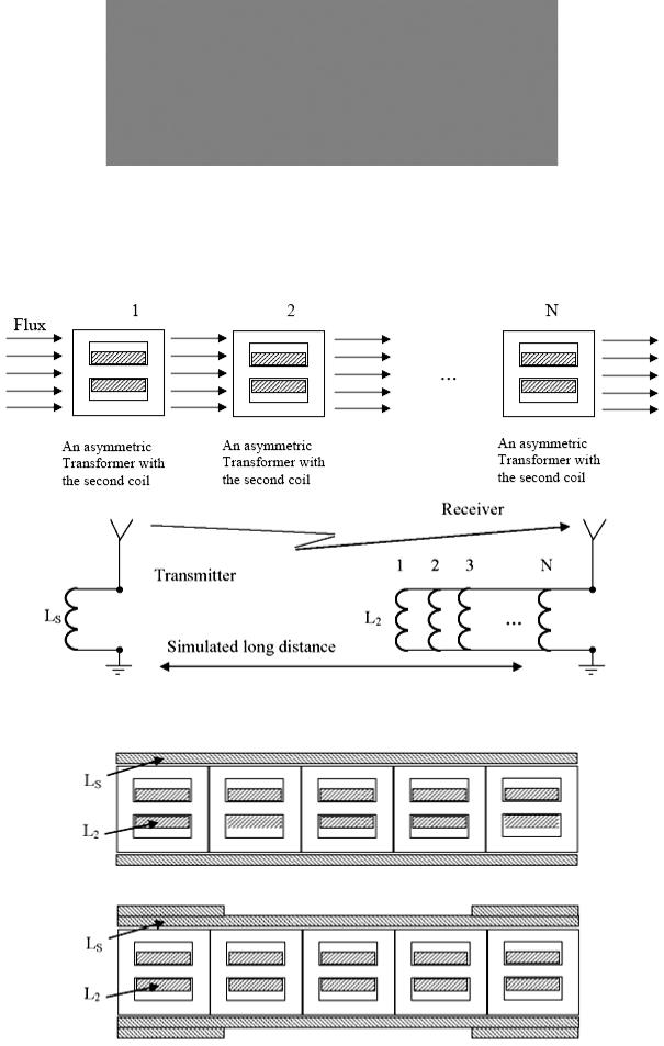
If a lot of asymmetric transformers are placed with a common flux flow through them, they will have no influence on this flux flow, as any one asymmetric transformer does not have any influence on the flux flow. If the secondary L2 transformer coils are then connected in parallel, this produces current amplification.
AS A RESULT
You have an asymmetric transformer arranged in a stack:
For flat (uniform) field inside of LS, it can be arranged with additional turns at it’s ends.
89

EXAMPLES OF COILS WHICH WERE ACTUALLY CONSTRUCTED
The coils are constructed from 5 sections, made from E-type ferrite core with a permeability of 2500, and wound using plastic-covered wire. The central sections L2 have 25 turns, and edge sections have 36 turns (to equalise the voltage on them). All sections are connected in parallel. The coil LS has field-flattening turns at it’s ends, and a single-layer winding LS was used, the number of turns depending on the diameter of the wire used.
The current amplification for these particular coils is 4 times.
Changing LS inductance is 3% (if L2 is short-circuited)
SECRET 5
The power source in Nikola Tesla car “Red arrow” is
FERROMAGNETIC RESONANCE
COMMENT: To understand electromagnetic feedback, you must consider the action to be like that of domains which have a group behaviour, or alternatively, spin waves (like a row of standing dominos falling over where each one is toppled by the previous one hitting it).
90