

Ebooki / FREE_ENERGY_NIKOLA_TESLA_SECRETS_FOR_EVE
.pdfStill further testing
Charging a capacitor by shunting current in oscillation mode.
Conditions: The addition of a charging capacitor of 47 nano Farads.
The result: A capacitor is charging without shunting the circuit. The final voltage on it is 0.8 V, and rises an falls of the voltage depend on the value of the capacitor.
THE OVERALL RESULTS OF THE TESTS (OPTIONS 1, 2 and 3)
The symmetry of interaction in systems with electromagnetic field feedback (as with switched inductance) appears to be violated, and this implies that this arrangement could be used to generate energy.
COMMENT: You need to choose the load in order to get the maximum power output. Very low, and very high loads, will send almost no energy to the load.
61
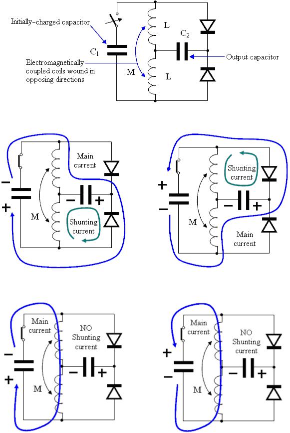
ILLUSTRATION FOR SWITCHABLE INDUCTANCE
EXPLANATION: The circuit has two kinds of currents: the main current and the shunting current.
The main and the shunting currents run through the same output capacitor in one direction, if the output capacitor is discharged.
There is no shunting current, if the output capacitor is charged.
62
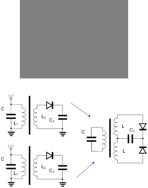
ILLUSTRATION FOR SWITCHABLE INDUCTANCE
From Don Smith
EXPLANATION As Don Smith said, two detector receivers were combined, and one FE device was constructed.
COMMENTS: Don Smith produced this explanation as a PDF file: www.free-energy-info.com/Smith.pdf The resistance of the load must be chosen so as to get the maximum possible power in it.
The “board” does not contain an output circuit, because a couple of spark gaps and one step-down transformer can be used instead of diodes and a capacitor (this was pointed out before, so read the part which describes the suppression of back EMF).
63
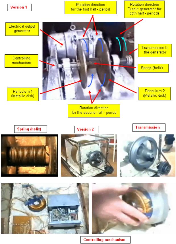
MECHANICAL (INERTIAL) ANALOGUE OF SWITCHABLE INDUCTANCE
From Tariel Kapanadze
EXPLANATION: When one pendulum is stopping the other is accelerating. The controlling mechanism connects the pendulums to the output generator one after the other and so maintains the oscillations.
64
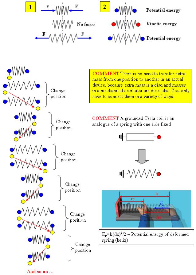
CONNECTING EXTRA MASS TO A MECHANICAL OSCILLATOR
EXPLANATION: Mechanical energy can be stored in any spring by compressing it or stretching it (1). It corresponds to two positions in a mechanical oscillator (2), when only potential energy takes place in an oscillating process
EXPLANATION: If extra mass is connecting periodically to one side or the other, of a mechanical oscillator, it will be shifting without any energy loss during the oscillation process
65
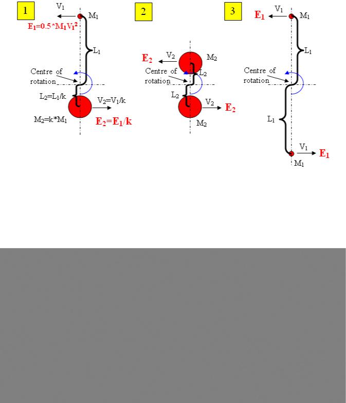
THE PRINCIPLE OF AMPLIFICATION OF MECHANICAL ENERGY
Explanation: The principle is based on an asymmetrical flywheel (1) consisting of a small mass and a large mass. These masses are balanced across the centre of rotation, that is, are located at a distance proportional to their weights, from the center of rotation. This helps to avoid vibration when they are rotating (the same principle used when balancing a car wheel).
The inertial moment of such a flywheel (1) is analogous to the inertial moments of flywheels (2) and (3), consisting only of large or small masses. However, from the point of view of kinetic energy, all of these examples, (1), (2) and (3) are different. This is because the kinetic energy of every mass depends on the direction and speed at which it moves (if is released during rotation). The highest common kinetic energy is in the masses of flywheel (3), as less energy is contained in flywheel (1) and the smallest kinetic energy is in flywheel (2). In order to get an increase in energy one needs to achieve a set-up which is based on a spring (for energy transformation from kinetic energy to potential energy and back again) and a lever of Archimedes (for changing the point where the force is applied).
Comments:
1.The simplified schematic diagrams shown here are for explanation purposes only.
2.In an actual device, you can use a spring in rotation mode (as Tariel Kapanadze did).
3.You can use disks and rings as flywheel masses (as Tariel Kapanadze did).
4.Altering one mass to another is actually achieved by connecting them in various ways.
66
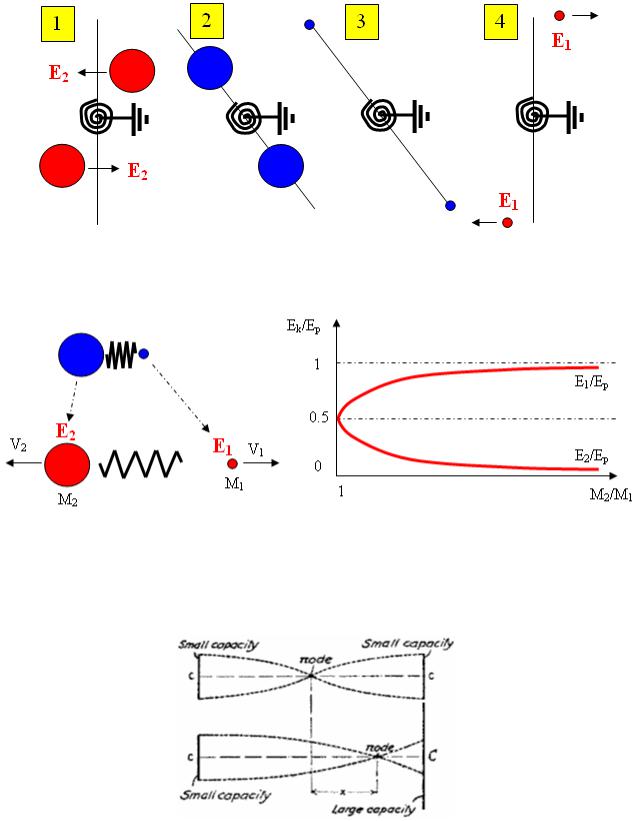
Comment: Any asymmetrical mechanical oscillator behaves as indicated above, when the potential energy of a compressed spring is transformed to the kinetic energy of moving masses.
The potential energy of the spring is distributed unequally between the small and large masses. A small mass acquires more energy relative to it’s size than a large mass does. The sum of the kinetic energies of both masses is equal to the potential energy of the spring.
Comment: This is based on Tesla’s asymmetrical schematic:
67
FLYWHEEL – A HIDDEN FORM OF ENERGY
(Clarifications on mechanical energy amplification)
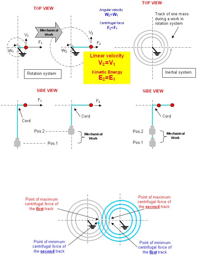
EXPLANATION: If you don’t want to lose mechanical energy when doing work, then this work must be done by an imaging force. This force is absent in an inertial coordinate system, but it is present in a non-inertial coordinate system. When in a rotational coordinate system this force is called ‘centrifugal’ force.
COMMENT: After the work is done, the centrifugal force is low and if you want to continue producing mechanical work, you have to use the other coordinate system where centrifugal force is high again. This is possible because linear velocity does not change. You have to provide the other support point only (and a cord) in order to produce mechanical energy again.
COMMENT: If you want to make this mechanical work continuous, then the end of the first track must also be the beginning of the second track. You have to change coordinate system periodically.
COMMENT: In a real situation, you have to compensate for energy loss due to friction and so a part of the excess energy must be used to maintain the process.
68
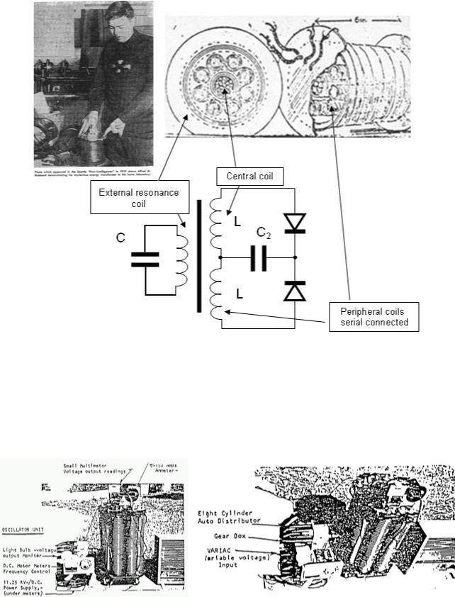
ILLUSTRATION FOR SWITCHABLE INDUCTANCE
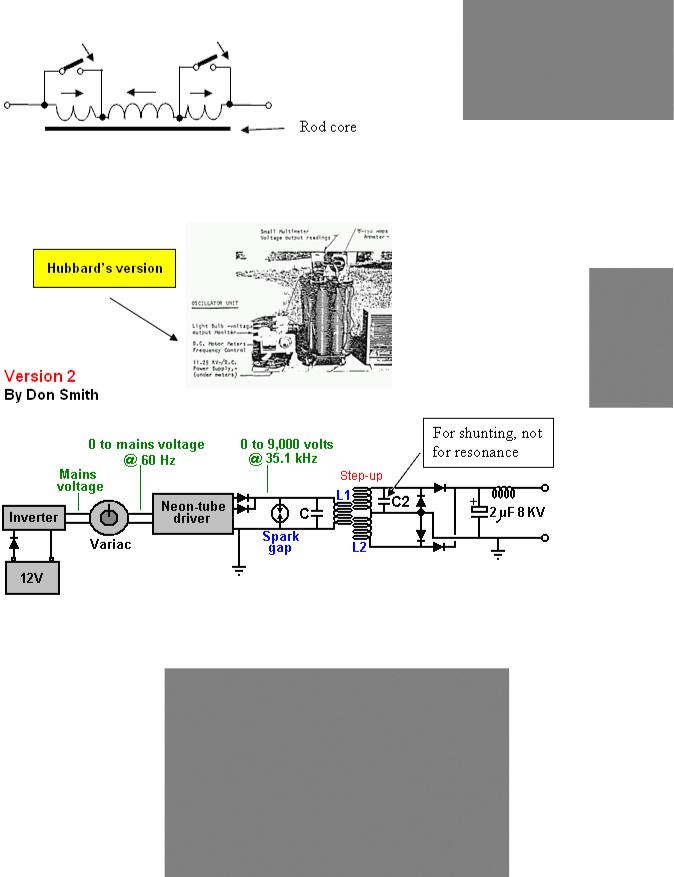
From Alfred Hubbard
EXPLANATION: The center coil and all of the peripheral coils can “grasp” the same flux coming from the resonance coil. All other details are the same as in Smith’s version.
COMMENTS: In other words, you can use rods as the coil core, instead of a closed ferromagnetic core.
But, this is not the only option in Hubbard’s device. He may have had another one, based on a different principle, perhaps the principle of energy amplification in an LC circuit as described earlier, but with switchable inductance being used.
69
MODERN OPTIONS?
In switchable inductance
Version 1
A coil has more inductance when some of it’s parts are short-circuited:
EXPLANATION: The central section of the coil and it’s two end sections are wound in opposite directions.
COMMENT: The coil shown in the picture above has twice the inductance, when it’s end sections are shortcircuited (measurements made with the Chinese-built RLC test meter shown here):
But, this looks like resonance in an asymmetrical transformer ?????
Version 3
By Tariel Kapanadze
No description …???
Read on for further details…. 70