

Ebooki / FREE_ENERGY_NIKOLA_TESLA_SECRETS_FOR_EVE
.pdfCOMMENT: Charges from the ground will run on to the right hand plate UNTIL the moment when the external field drops to zero caused by the second spark (“S2”). It takes more charges flowing from the ground to annihilate the external field at the instant of the second spark, because the capacitance of the plate on the right is far greater. ‘More charge’ means ‘more current’, so you have achieved current amplification through this arrangement.
COMMENT: The field at the terminals of the plate on the right is not zero after both sparks have occurred, this is because a field remains due to the additional charges which have flowed in (‘pumped’) from the ground.
41

THE SIMPLEST ASYMMETRICAL CAPACITORS
The most simple asymmetrical capacitors are the Leyden jar and the coaxial cable (also invented by Mr. Tesla).
Apart from the fact that the area (capacitance) of the plates of these capacitors is different, and they therefore are asymmetrical, they have another property:
The electrostatic field of the external electrode of these devices does not affect the internal electrode.
EXPLANATION: This is caused by the fact that the electrostatic field is absent inside the metal bodies (see textbooks).
REMARK: This is true provided that the plates are charged separately.
CAPACITOR - TRIODE
REMARK: Dr. Harold Aspden has pointed out the possibility of Energy Amplification when using this device.
42

THE PRINCIPLE OF CURRENT AMPLIFICATION
IN THE CAPACITOR – TRIODE
EXPLANATION: You have to get zero potential on the inside of a small cylinder (on the input electrode). In this case, the charge on the external cylinder will be more than on the internal cylinder. More charge means more current, and so you’ll have current amplification.
In detail:
The potential around any cylinder with radius ‘R’ is:
where q is a charge on this cylinder
Potential inside this cylinder is the same, because:
and
If you want to get zero potential inside two cylinders (on the input electrode) you have to deliver more charge of the opposite sign to the external one, proportionally to the radius of this cylinder. A larger radius means more charge.
OPERATIONAL SEQUENCE:
1.Charge the input electrode from your source of energy.
2.The small cylinder (control electrode) will be charged automatically, if it’s connected to the ground through a diode with the properly polarity.
3.Discharge the input electrode to zero level (for example, by using a spark). As a result there will be a zero potential on it.
4.If the external cylinder is connected to the ground through a diode with the properly polarity, it will be charged automatically with the opposite sign. But the charge “pumped” from the ground will more than for small cylinder (proportional to the ratio of their radiuses).
5.As a result, there is current amplification.
COMMENT: Did Edwin Gray use this principle in his device?.
COMMENT: If so, then Gray’s patent is lacking some very important details (???) 43

THE PRINCIPLE OF THE “BLINDNESS”
CHARGING SYSTEM IN THE SEG
EXPLANATION: The “short” coil is not able to see the oscillations in the “long” coil, because the total number of magnetic lines from the “long” coil which are passing through the “short” coil is close to zero (because one half is in one direction and the other half is in the opposite direction).
COMMENT: This a particular case of an asymmetrical transformer, for more details read the part about asymmetrical transformers.
44
COMMENTS ABOUT THE SEG:
All Back EMF schematics can be used in SEG
COMMENTS: No current will be produced in the load in any of these circuits, unless there is a ground connection. Is excitation possible with just a single spark (???)
45

FOR MORE ASYMMETRY IN SEG ?
FOR ONE SPARK EXCITING IN SEG ?
By Don Smith
COMMENT: This arrangement becomes more asymmetrical after excitation
46

EXPLANATION
Symmetry is destroyed by a spark
If the impedances of Ra and Rc are the same at the frequency produced by signal generator F1, then the resulting voltage at points A and B will also be identical which means that there will be zero output.
If the circuit is excited by the very sharp, positive-only, DC voltage spike produced by a spark, then the impedances of Ra and Rc are not the same and there is a non-zero output.
Here is a possible alternative. Please note that the position of the output coil must be adjusted, it’s best position depending on value of resistor Rc and the frequency being produced by signal generator F1.
Here is another possible arrangement. Here, the position of the output coil depends on L1 and L2:
47

A NOMOGRAPH
Using a nomograph: Draw a straight line from your chosen 30 kHz frequency (purple line) through your chosen 100 nanofarad capacitor value and carry the line on as far as the (blue) inductance line as shown above.
You can now read the reactance off the red line, which looks like 51 ohms to me. This means that when the circuit is running at a frequency of 30 kHz, then the current flow through your 100 nF capacitor will be the same as through a 51 ohm resistor. Reading off the blue "Inductance" line that same current flow at that frequency would occur with a coil which has an inductance of 0.28 millihenries.
48

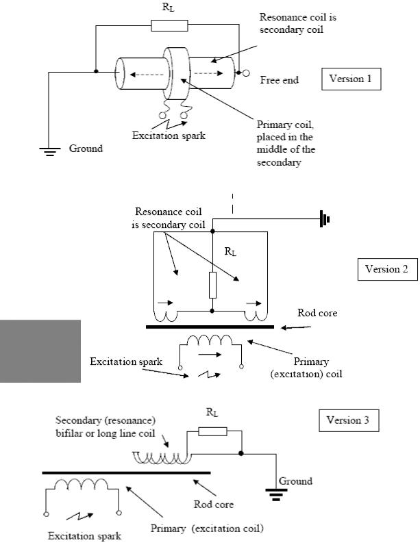
MODERN OPTIONS IN SEG
Back EMF suppression in resonance coil
Version 3
By Don Smith
COMMENT: Please note that a long wire is used and one-spark excitation, where additional capacitors are used to create non-symmetry (???)
Version???
By Don Smith
Multi coil system for energy multiplication
Version???
By Tariel Kapanadze
No description, so read the following section…
49

KAPANADZE PROCESS
The process requires only 4 steps:
STEP 1
An L-C (coil-capacitor) circuit is pulsed and it’s resonant frequency determined (possibly by feeding it power through a spark gap and adjusting a nearby coil for maximum power collection).
STEP 2
The SEG process causes the energy level in the L-C circuit to rise. Power is fed via a spark gap which produces a very sharp square wave signal which contains every frequency in it. The L-C circuit automatically resonates at it’s own frequency in the same way that a bell always produces the same musical frequency when struck, no matter how it is struck.
STEP 3
The output waveform from the L-C circuit is then manipulated to provide an output which oscillates at the frequency on the local mains supply (50 Hz or 60 Hz typically).
STEP 4
Finally, the oscillations are smoothed by filtering to provide mains-frequency output power.
COMMENT: All of these processes are described in Kapanadze’s patents and so, no state or private confidential information is shown here. Kapanadze’s process is the SEG process.
COMMENT: As I see it, the main difference between the designs of Don Smith and Tariel Kapanadze is the inverter or modulator in the output circuit. At mains frequency you need a huge transformer core in a powerful inverter.
Read the following parts to discover more secrets…
50