

диафрагмированные волноводные фильтры / 4acd4ee7-6036-49c2-9569-93c05a33de47
.pdfThis article has been accepted for publication in a future issue of this journal, but has not been fully edited. Content may change prior to final publication. Citation information: DOI 10.1109/ACCESS.2018.2803790, IEEE Access
Date of publication xxxx 00, 0000, date of current version xxxx 00, 0000.
Digital Object Identifier 10.1109/ACCESS.2017.Doi Number
Dual-Polarized Filtering Antenna With Printed
Jerusalem-Cross Radiator
Changzhou Hua1, Rongzheng Li1, Yi Wang2, Senior Member, IEEE, and Yunlong Lu1
1Faculty of Electrical Engineering and Computer Science, Ningbo University, Ningbo, 315211, China
2Department of Electronic, Electrical and Systems Engineering, University of Birmingham, B15 2TT, United Kingdom
Corresponding author: Changzhou Hua (e-mail: huachangzhou@ nbu.edu.cn).
This work was supported by the National Natural Science Foundation of China (61501274 and 61631012).
ABSTRACT This paper presents a design of dual-polarized antenna with embedded filtering circuits by using a printed Jerusalem-cross radiator and a ring slot-coupled feed structure. A square ring slot has been adopted to implement the coupling mechanism. It is excited by two orthogonal microstrip feedlines to achieve dual polarizations. Meanwhile, the slot-coupled feed network and printed Jerusalem-cross radiator form a coupled-resonator circuit that realizes a second-order bandpass filtering performance. Consequently, a dual-polarized antenna with a filtering performance is obtained without using extra filtering circuits. To demonstrate the idea, an antenna prototype operating at LTE bands 42 and 43 (3.4–3.8 GHz) is designed, fabricated, and measured. Measured results show that the proposed antenna provides good filtering and dual-polarized radiation performances. Furthermore, a 4-element dual-polarized linear array is designed for high-gain applications.
INDEX TERMS Dual-polarized, filtering antenna, printed Jerusalem-cross radiator, slot-coupled.
I. INTRODUCTION
In wireless communication systems, it is common that the antenna and filter are designed as two independent components and then cascaded together. In this case, additional transmission lines are required for interconnecting them, which inevitably increases system size and introduces extra loss. In recent years, filtering antenna has become an interesting topic [1]. A common method to design a filtering antenna is to cascade the filtering circuit and the antenna directly [2], [3]. This usually causes impedance mismatch and deteriorates the filtering performance, especially near the band edges. The filtering circuits inserted to the antenna feed networks also cause extra insertion loss degrade antenna gains and radiation patterns. To tackle this problem, filtering antennas without extra filtering circuits were proposed in [4], providing both the desired filtering and radiating performance. However, previously reported filtering antennas were mostly focused on single-polarizations [5]- [7]. Dual-polarized antennas are widely used in wireless communication systems because of their significant advantages of polarization diversity, enhanced channel capacity and reduced installation space [8]-[10]. In [11], a novel concept of multimode filtering antenna was applied
to dual-polarized antenna arrays. A compact dual-polarized filtering antenna without extra filtering circuit was presented at LTE band [12]. A quasi-elliptic bandpass response was achieved for both polarizations with high frequency selectivity and low cross polarization.
In this paper, a novel dual-polarized slot-coupled filtering antenna is proposed. It is composed of a printed Jerusalemcross radiator, a slot-coupled feed network and a conducting reflector. Although the Jerusalem-cross has been widely used in frequency selective surfaces [13], [14], it has not been used as a radiating element for filtering antennas. Commercial software ANSYS HFSS has been used to analyze and simulate this antenna. For demonstration, an antenna prototype operating at 3.6 GHz is designed, fabricated, and measured. Measured results show that, for both polarizations, the proposed filtering antenna exhibits a rapid roll-off at the upper and lower edges of the passband and achieves an isolation of 23 dB between the two ports. The gain of the filtering antenna is around 9 dBi. To improve the antenna gain, a four-element dual-polarized linear array is also designed, which achieves a gain of 14 dBi.
2169-3536 © 2017 IEEE. Translations and content mining are permitted for academic research only.
Personal use is also permitted, but republication/redistribution requires IEEE permission. 1
See http://www.ieee.org/publications_standards/publications/rights/index.html for more information.
2169-3536 (c) 2018 IEEE. Translations and content mining are permitted for academic research only. Personal use is also permitted, but republication/redistribution requires IEEE permission. See http://www.ieee.org/publications_standards/publications/rights/index.html for more information.
This article has been accepted for publication in a future issue of this journal, but has not been fully edited. Content may change prior to final publication. Citation information: DOI 10.1109/ACCESS.2018.2803790, IEEE Access
II. STRUCTURE OF THE DUAL-POLARIZED FILTERING ANTENNA
The geometry of the proposed dual-polarized filtering antenna is illustrated in Fig. 1. It is a vertically coupled antenna consisting of three layers separated by air gaps. The printed Jerusalem-cross radiator is printed on the bottom side of the top-layer substrate. The slot-coupled feed network is printed on the middle-layer substrate, with the square-ring slot etched on its top side and two orthogonal microstrip feedlines printed on the bottom side to achieve dual polarizations. The feed line consists of a 50-Ω transmission line section and a narrow high-impedance one, optimized for impedance matching. It is noted that the square-slot ring is a defected ground structure in the ground plane that also serves the printed Jerusalem-cross radiator and the microstrip feedlines. A conducting reflector is placed at a distance from the middle-layer substrate to suppress back radiations and improve the antenna gains.
|
L1 |
|
|
|
|
P2 |
|
|
|
|
P1 |
|
|
|
|
|
W1 |
|
|
|
|
W2 |
|
|
|
|
S |
|
|
y |
L4 |
|
|
|
L3 |
|
W3 |
||
|
|
|||
|
L2 |
Port2 |
|
|
z |
x |
|
||
|
|
|||
|
|
L5 |
|
|
|
L6 |
Port1 |
|
|
Radiator |
|
Top layer |
||
|
|
|||
Ring slot |
h2 |
Middle layer |
||
|
|
|||
Feeding lines |
h1 |
Conducting |
||
reflector |
||||
|
|
|
||
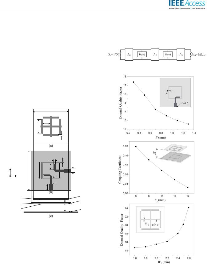
FIGURE 1. Geometry of the proposed dual-polarized filtering antenna.
(a) Printed Jerusalem-cross radiator. (b) Slot-coupled feed network (light gray: top side; dark gray: bottom side). (c) Side view.
III. THEORETICAL ANALYSIS AND DESIGN
The antenna can be interpreted as a filtering-circuit embedded antenna with two resonators. The first resonator is the square-ring slot fed by microstrip lines and the second is the printed Jerusalem-cross radiator. Without using any extra interface circuit, the transition loss between the filtering circuit and the antenna is minimized. The proposed filtering antenna can be regarded as a coupled-resonator circuit, shown in Fig. 2 [15], where Rrad represents the radiation resistance of the radiator. With this model, the design
VOLUME XX, 2017
procedure follows the extraction of three design parameters: the input/output external quality factors and the coupling coefficients. The values of these parameters depend on the desired characteristic of the filtering response, which can be determined by conventional filter synthesis theory [16].
FIGURE 2. Coupled-resonator model of the proposed filtering antenna.
(a)
(b)
(c)
FIGURE 3. (a) External quality factor QEA-in versus the gap S. (b) Coupling coefficient J12 versus the height h2. (c) External quality factor QEB-in versus the width W1.
9
2169-3536 (c) 2018 IEEE. Translations and content mining are permitted for academic research only. Personal use is also permitted, but republication/redistribution requires IEEE permission. See http://www.ieee.org/publications_standards/publications/rights/index.html for more information.

This article has been accepted for publication in a future issue of this journal, but has not been fully edited. Content may change prior to final publication. Citation information: DOI 10.1109/ACCESS.2018.2803790, IEEE Access
An antenna prototype operating at 3.6 GHz with a fractional bandwidth (FBW) of 12.4% is designed for demonstration. The design parameters are obtained as: J12 =
0.097 and QEA-in = QEB-out = 15.9. Ansoft HFSS is used to establish the relationship of the design parameters with the
physical dimensions of the antenna structure. The extraction of J12 and QEA-in follows the method in [16]. Fig. 3(a) shows the external quality factor QEA-in versus the width of the ring slot. Fig. 3(b) shows the coupling coefficient versus the height h2. The external quality factor QEB-out is extracted using the following equation [17]
QEB out |
|
f0 |
|
|
d Im(Zin ) |
|
|
|
|
|
(1) |
||||
2 Re(Zin |
( f0 )) |
|
df |
|
f f0 |
||
|
|
|
|
|
|||
where Zin is the input impedance of the structure seen from Port B as shown in Fig. 3(c).
(a) Port1 is excited |
(b) Port2 is excited |
FIGURE 4. Simulated current distributions of the Jerusalem-cross radiator.
Besides the bandpass filtering responses, the proposed antenna also exhibits dual-polarization behavior. The simulated surface current distributions of the Jerusalem-cross radiator are given to help explain the dual-polarized performance of the antenna. Fig. 4 illustrates the surface currents distributions of each linear polarization at 3.6 GHz, respectively. When Port 1 (see Fig. 1) is excited, the current on the printed Jerusalem-cross radiator distributes along the y-axis. The yoz plane becomes the E-plane and the xoz plane is the H-plane. When Port 2 is excited, the xoz plane is the E- plane whereas the yoz plane denotes the H-plane.
IV. EXPERIMENTAL RESULTS
A. SINGLE ELEMENT DUAL-POLARIZED FILTERING ANTENNA
Fig. 5 shows a photograph of the fabricated antenna. The Jerusalem-cross radiator is printed on the bottom side of a FR4 substrate with a relative permittivity of 4.4 and a loss tangent of 0.02, and the slot-coupled feed network is printed on a Rogers RO4003 substrate with a relative permittivity of 3.55 and a loss tangent of 0.0027. The two substrate layers are separated by nylon pillars, which have negligible effect on the antenna performance. An alumina plate is placed underneath the two substrate layers as a reflector to reduce
back radiations and improve the antenna gains. The dimensions of the antenna are listed in Table I.
FIGURE 5. Photograph of the fabricated dual-polarized filtering antenna prototype.
TABLE I
DIMENSIONS OF THE PROPOSED FILTERING ANTENNA
Parameter |
Value |
Parameter |
Value |
|
(mm) |
(mm) |
|||
|
|
|||
|
|
|
|
|
L1 |
60 |
W1 |
2 |
|
L2 |
70 |
W2 |
1 |
|
L3 |
17.3 |
W3 |
3.7 |
|
L4 |
6.5 |
P1 |
24 |
|
L5 |
13 |
P2 |
11.8 |
|
L6 |
15 |
h1 |
22 |
|
S |
0.5 |
h2 |
10 |
|
|
|
|
|
|
|
|
|
|
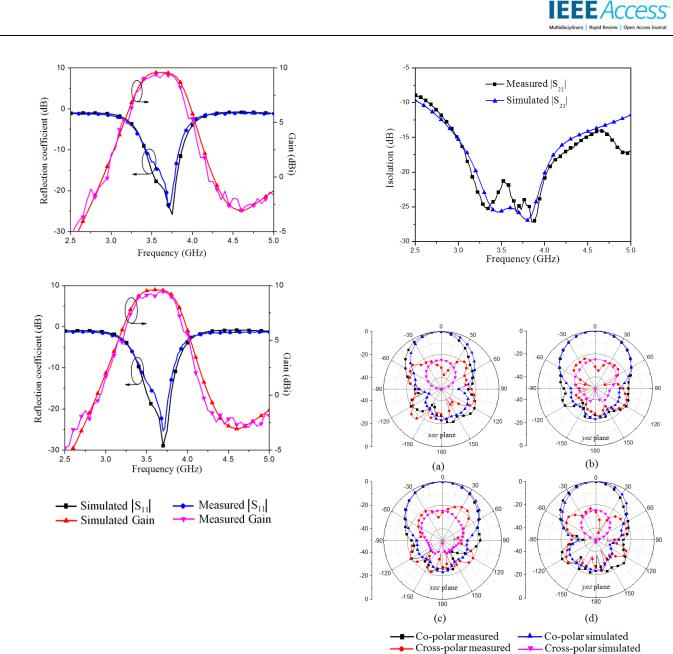
The simulated and measured reflection coefficients and gains for the two feed ports of the proposed dual-polarized antenna are shown in Fig. 6. The reflection coefficients of the antenna were measured using an Agilent N5230A network analyzer, while the antenna gain and radiation pattern were measured in a Satimo Starlab system. It can be seen that the simulated and measured results agree very well with each other. The small error is mainly due to fabrication tolerance and experimental imperfection. The measured 10 dB impedance bandwidths for both ports are 12%, which cover the LTE bands 42 and 43 (3.4–3.8 GHz). With reference to the gain curves, a good bandpass filtering response has been achieved. It is seen that the antenna has a flat gain curve within the passband, with an average value of ~9 dBi. The gain drops significantly near the passband edge, leading to high frequency selectivity. Fig. 7 shows the simulated and measured isolations between the two feed ports. It is seen that the measured results also agree well with the simulations. At the central operating frequency of 3.6 GHz, the isolation between the two ports is better than 23 dB. This indicates that the coupling between the two polarizations is weak.
VOLUME XX, 2017 |
9 |
2169-3536 (c) 2018 IEEE. Translations and content mining are permitted for academic research only. Personal use is also permitted, but republication/redistribution requires IEEE permission. See http://www.ieee.org/publications_standards/publications/rights/index.html for more information.
This article has been accepted for publication in a future issue of this journal, but has not been fully edited. Content may change prior to final publication. Citation information: DOI 10.1109/ACCESS.2018.2803790, IEEE Access
(a)
FIGURE 7. Simulated and measured isolations between the two feed ports.
(b)
FIGURE 6. Simulated and measured reflection coefficients and gains.
(a) Port 1. (b) Port 2.
Figs. 8(a) and (b) show the simulated and measured radiation patterns of the antenna in the two orthogonal planes (xoz plane and yoz plane) at 3.6 GHz when port 1 is excited and the port 2 is terminated with a 50 Ω load. It is observed that broadside radiation characteristics are obtained. The maximum radiation occurs in the broadside (+z) direction. The measured co-polar fields are 25 dB stronger than the cross-polar counterparts. The measured front-to-back ratios are more than 25 dB. The simulated and measured results agree well with each other, exhibiting a maximum radiation in the broadside. Figs. 8(c) and (d) show the simulated and measured radiation patterns at 3.6 GHz when port 2 is excited, whereas port 1 is terminated with a 50 Ω load. The antenna exhibits a similarly radiation patterns as port 1 excitation. The cross-polarization levels are better than 25 dB in the two orthogonal planes. The measured front-to-back ratios are also more than 25 dB. The difference between the simulated and measured radiation patterns is mainly due to the influence of the fixtures, screws, and feed setup including SMA connectors and cables near the antenna under test.
FIGURE 8. Simulated and measured radiation patterns of the antenna at 3.6 GHz. (a) and (b) for Port 1. (c) and (d) for Port 2.
B. 4-ELEMENT DUAL-POLARIZED FILTERING ANTENNA ARRAY
Base on the filtering antenna discussed above, a 4-element dual-polarized linear array is designed. Fig. 9 shows the layout of the antenna array. A microstrip feed network is designed for both polarizations by utilizing a T-junction power divider. An antenna inter-elemental distance of 60 mm (about 0.72 λ0, where λ0 is the free space wavelength of the central operating frequency of 3.6 GHz) is chosen to emulate phased-array conditions where grating lobes would be minimized.
VOLUME XX, 2017 |
9 |
2169-3536 (c) 2018 IEEE. Translations and content mining are permitted for academic research only. Personal use is also permitted, but republication/redistribution requires IEEE permission. See http://www.ieee.org/publications_standards/publications/rights/index.html for more information.
This article has been accepted for publication in a future issue of this journal, but has not been fully edited. Content may change prior to final publication. Citation information: DOI 10.1109/ACCESS.2018.2803790, IEEE Access
60mm
(a)
y |
port2 |
z
 x
x
187mm
port1
270mm
(b)
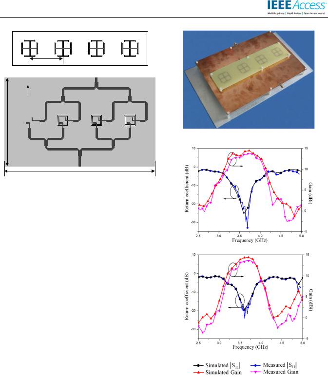
FIGURE 9. Layout of the 4-element dual polarized filtering antenna array: (a) Jerusalem-cross radiator and (b) feed network (light gray: top side; dark gray: bottom side).
Fig. 10 shows a photograph of the fabricated dualpolarized antenna array. The simulated and measured reflection coefficients and gains are illustrated in Fig 11. The measured 10-dB impedance bandwidth for ports 1 and 2 are 14% (3.33–3.83 GHz) and 10.5% (3.43–3.81 GHz), respectively. With reference to the gain curves, good bandpass filtering responses are achieved again. The measured average gains within the passband are ~14 dBi. It is worth mentioning that, for the element, due to rotational symmetry, the bandwidths of the two polarizations are expected to be the same. As for the array, the difference in bandwidth is likely a result of coupling between the elements. When port 1 is excited, the vertical arms of the Jerusalemcross radiator in y direction are activated (see Fig. 4). Because the vertical arms are closer to each other than the horizontal ones, the stronger mutual coupling potentially causes wider bandwidth.
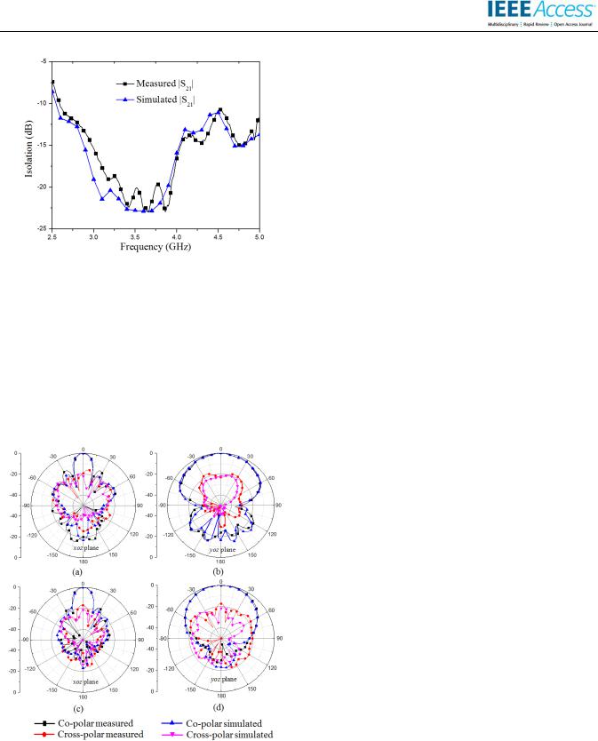
The simulated and measured isolation between the two ports of the antenna array are shown in Fig. 12. Reasonably good agreement has been achieved. The measured isolation between the two ports for exciting radiations with different polarizations is better than 22 dB at the central frequency of 3.6 GHz.
FIGURE 10. Photograph of the fabricated dual-polarized antenna array.
(a)
(b)
FIGURE 11. Simulated and measured reflection coefficients and gains of the antenna array for (a) Port 1 and (b) Port 2.
VOLUME XX, 2017 |
9 |
2169-3536 (c) 2018 IEEE. Translations and content mining are permitted for academic research only. Personal use is also permitted, but republication/redistribution requires IEEE permission. See http://www.ieee.org/publications_standards/publications/rights/index.html for more information.
This article has been accepted for publication in a future issue of this journal, but has not been fully edited. Content may change prior to final publication. Citation information: DOI 10.1109/ACCESS.2018.2803790, IEEE Access
FIGURE 12. Simulated and measured isolations between two feed ports.
Fig. 13 shows the measured and simulated radiation patterns at 3.6 GHz, which are in good agreement. As a linear array, the antenna exhibits fan-beam radiation patterns. When port 1 is excited, the measured 3-dB beamwidths are 11° and 44° in the xoz- and yoz-planes. When port 2 is excited, the measured 3-dB beamwidths are 12°and 52°in the xoz- and yoz-planes, respectively. The measured copolarization is at least 19 dB higher than the crosspolarization counterpart. The measured front-to-back ratios are over 27 dB.
FIGURE 13. Simulated and measured radiation patterns of the antenna array at 3.6 GHz. (a) and (b) for Port 1. (c) and (d) for Port 2.
V. CONCLUSION
This paper presented a detailed design of a novel dualpolarized antenna with embedded filtering circuits. By using a square-ring slot-coupled feed structure together with the printed Jerusalem-cross radiator, a second-order filtering performance has been achieved. The square ring slot has been adopted to implement the coupling mechanism, which is excited by two orthogonal microstrip feedlines to achieve dual polarizations. An antenna prototype operating at LTE band 42 and 43 (3.4–3.8 GHz) has been designed, fabricated, and measured. Measured results show that the antenna prototype provides second-order filtering and dual-polarized radiating performance simultaneously. For both feed ports, the antenna has an average gain of 9 dBi in the passband and the gain drops significantly near the passband edge leading to high frequency selectivity. The isolation between the two ports is better than 23 dB. Meanwhile, stable broadside radiation characteristics with low cross-polarization and low backward radiation levels have been obtained for both feed ports. Finally, to improve the antenna gain, a 4-element dualpolarized linear array has been designed. For both feed ports, measured results show that the antenna array has achieved a gain of 14 dBi, and maintains good filtering characteristics.
REFERENCES
[1]C.-T. Chuang and S.-J. Chung, “Synthesis and design of a new printed filtering antenna,” IEEE Trans. Antennas Propag., vol. 59, no. 3, pp. 1036–1042, Mar. 2011.
[2]C.-K. Lin and S.-J. Chung, “A compact filtering microstrip antenna with quasi-elliptic broadside antenna gain response,” IEEE Antennas Wireless Propag. Lett., vol. 10, pp. 381–384, May 2011.
[3]Z. H. Jiang and D. H. Werner, “A compact, wideband circularly polarized co-designed filtering antenna and its application for wearable devices with low SAR,” IEEE Trans. Antennas Propag., vol. 63, no. 9, pp. 3808–3818, Sep. 2015.
[4]X. Y. Zhang, W. Duan, and Y.-M. Pan, “High-gain filtering patch antenna without extra circuit,” IEEE Trans. Antennas Propag., vol. 63, no. 12, pp. 5883–5888, Dec. 2015.
[5]H. Chu, C. Jin, J.-X. Chen, and Y.-X. Guo, “A 3-D millimeter-wave filtering antenna with high selectivity and low cross-polarization,” IEEE Trans. Antennas Propag., vol. 63, no. 5, pp. 2375–2380, Mar. 2015.
[6]J. Shi X. Wu, Z. N. Chen, and X. Qing, “A compact differential filtering quasi-Yagi antenna with high frequency selectivity and low cross polarization levels,” IEEE Antennas Wireless Propag. Lett., vol. 14, pp. 1573–1576, 2015.
[7]X. W. Chen, F. X. Zhao, L. Y. Yan, and W. M. Zhang, “A compact filtering antenna with flat gain response within the passband”, IEEE Ant. & Wire. Prop. Lett., vol. 12,2013 pp. 857-860.
[8]B. G. Porter, L. L. Rauth, J. R. Mura, and S. S. Gearhart, “Dualpolarized slot-coupled patch antennas on duroid with teflon lenses for 76.5-GHz automotive radar systems,” IEEE Trans. Antennas Propag., vol. 47, pp. 1836–1842, Dec. 1999.
[9]Y. Wang and Z. Du, “Dual-polarized slot-coupled microstrip antenna array with stable active element pattern,” IEEE Trans. Antennas Propag., vol. 63, no. 9, pp. 4239–4244, Sep. 2015.
[10]R. Z. Li, C. Z. Hua, and Y. L. Lu, et al, “Dual-polarized aperturecoupled filtering antenna,” in Proc. iWEM, pp. 152–153, 2017.
[11]C. X. Mao, S. Gao, Y. Wang, F. Qin, Q. Chu, “Multi-mode resonator-fed dual polarized antenna array with enhanced bandwidth and selectivity”, IEEE Trans. Antennas Propag., vol. 63, no. 12, pp. 5492–5499, 2015.
VOLUME XX, 2017 |
9 |
2169-3536 (c) 2018 IEEE. Translations and content mining are permitted for academic research only. Personal use is also permitted, but republication/redistribution requires IEEE permission. See http://www.ieee.org/publications_standards/publications/rights/index.html for more information.

This article has been accepted for publication in a future issue of this journal, but has not been fully edited. Content may change prior to final publication. Citation information: DOI 10.1109/ACCESS.2018.2803790, IEEE Access
[12]W. Duan, X. Y. Zhang, Y.-M. Pan, J. X. Xu and Q. Xue, “Dualpolarized filtering antenna with high selectivity and low cross polarization,” IEEE Trans. Antennas Propag., vol. 64, no. 10, pp. 4188–4196, Dec. 2016.
[13]B.A. Munk, Frequency Selective Surfaces-Theory and Design. New York: Wiley, 2000.
[14]T. K. Wu, Frequency Selective Surfaces and Grid Array, WileyInterscience, 1995.
[15]O.-A. Nova, J.-C. Bohorquez, N.-M. Peña, G.-E. Bridges, L. Shafai, and C. Shafai, “Filter-antenna module using substrate integrated waveguide cavities,” IEEE Antennas Wireless Propag. Lett., vol. 10, pp. 59–62, Mar. 2011.
[16]J.-S. Hong and M. J. Lancaster, Microstrip Filters for RF/Microwave Applications. New York, NY, USA: Wiley, 2001.
[17]Y. Yusuf and X. Gong, “Compact low-loss integration of high-Q 3-D filters with highly efficient antennas,” IEEE Trans. Microw. Theory Techn.,vol. 59, no. 4, pp. 857–865, Apr. 2011.
VOLUME XX, 2017 |
9 |
2169-3536 (c) 2018 IEEE. Translations and content mining are permitted for academic research only. Personal use is also permitted, but republication/redistribution requires IEEE permission. See http://www.ieee.org/publications_standards/publications/rights/index.html for more information.