

диафрагмированные волноводные фильтры / aa11b764-f9f3-4cca-ba96-78143ee52fa8
.pdfCompact Arrays Fed by Substrate Integrated Waveguides
J. Lacik, T. Mikulasek, J. Puskely, Z. Raida, and D. Wolansky
Abstract − In this paper, we compare three different concepts of compact antenna arrays fed by substrate integrated waveguides (SIW). Antenna concepts differ in the type of radiators. Slots represent magnetic linear radiators, patches are electric surface radiators, and Vivaldi slots belong to travelling-wave antennas. Hence, the SIW feeders have to exploit different mechanisms of exciting antenna elements. Impedance and radiation properties of studied antenna arrays have been related to the normalized frequency. Antenna arrays have been mutually compared to show fundamental dependencies of final parameters of the designed antennas on state variables of antennas, on SIW feeder architectures and on related implementation details.
1 INTRODUCTION
Substrate integrated waveguides (SIW) have been proposed for a low-cost fabrication of waveguide structures [1]:
•SIW can be fabricated from conventional microwave substrates;
•Properties of SIW are comparable to the
parameters of conventional metallic waveguides. Thanks to SIW, active circuits, passive components, and radiating elements, can be
integrated into the same substrate.
SIW feeders are attractive to be used for the excitation of millimeter-wave antennas:
•Parasitic radiation of SIW feeders is negligible compared to microstrip transmission lines and coplanar waveguides;
•Integration of the feeder into a substrate to feed
antenna elements via apertures results in a compact architecture of the antenna array.
In the paper, we exploit SIW for an efficient feeding of three different antenna arrays:
•The array of slots represents a set of magnetic linear radiators;
•The array of patches is a system of electric surface radiators;
•The array of Vivaldi elements can be understood
as a set of travelling-wave sources.
All the three described compact arrays were designed for the operation in the Ka frequency band (see Table 1). Since central frequency of the operation of antenna arrays to be compared differs, frequency responses of antennas have been related to the normalized frequency and compared.
In Section 2, we briefly introduce the designed antenna arrays to be compared. Section 3 summarizes and compares outputs of simulations of antenna arrays. In Section 4, simulated results are experimentally verified. Section 5 concludes the paper.
|
Slot |
Vivaldi |
Patch |
|
|
|
|
fmin [GHz] |
26.5 |
31.0 |
29.0 |
fcentral [GHz] |
27.0 |
32.2 |
30.5 |
fmax [GHz] |
27.5 |
34.0 |
32.0 |
Table 1: Operational frequencies of studied SIW-fed antenna arrays.
2 DESIGNED ARRAYS
In the following paragraphs, we provide details of the design of the studied SIW-fed antenna arrays.
2.1 Slot array
In [2], we described the design of the slot array for operation in the bandwidth from fmin = 26.5 GHz to fmax = 27.5 GHz. The antenna was designed adopting Elliott’s procedure. The antenna array consisted of a transition between the metallic rectangular waveguide and the SIW, the 10-way feeding divider,
and the array of 10 linear |
slot arrays |
containing |
10 radiating elements. The |
antenna |
size was |
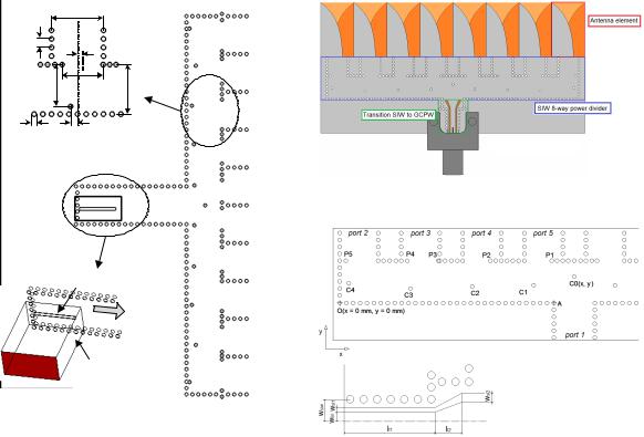
65 mm × 105 mm × 12 mm including a radome. The structure of the array is depicted in Figure 1.
The array was designed for the TACONIC substrate
TLY-5 (dielectric |
constant |
εr = 2.20, |
thickness |
h = 0.79 mm). The |
radome |
was of the |
dielectric |
constant εr, rad = 2.77 and thickness hrad = 2.00 mm. The feeding network consisted of a transition from
the rectangular waveguide to SIW and a 10-way
array of radiating slots
power divider
|
substrate |
|
flange |
metalized via holes |
|
aluminium plates |
||
UBR320 |
||
screws and nuts |
radome |
RWG-to-SIW transition antenna input
Figure 1: Slot array fed by SIW: radome removed (top), cut view (bottom).
________________________________________________________________________________________
Dept. of Radio Electronics, Brno University of Technology, Technicka 12, 616 00 Brno, Czech Republic, e-mail: raida@feec.vutbr.cz, tel.: +420.541.146.555, fax: +420.541.146.597.
978-1-4673-5692-3/13/$31.00 ©2013 IEEE
448
|
wSIW |
|
pvia |
port 2 |
|
rn |
||
|
pn |
sn |
port 3 |
|
wf |
|||
|
|||
|
|
port 4 |
|
dvia |
qn |
port 5 |
|
|
|
port 6
|
coupling slot |
|
TE |
|
10 |
port 1 |
air-filled |
|
RWG |
Figure 2: Structure of the rectangular waveguide to SIW transition and the power divider.
power divider (see Figure 2). The excitation power propagating in the rectangular waveguide was coupled to SIW through an aperture located in the output wall of the waveguide. The coupling slot was ls = 5.32 mm long and ws = 0.40 mm wide.
In the operation band, the designed antenna showed the reflection coefficient |S11| <−6 dB, the gain varied
from Gmin = 20.0 dB to Gmax = 22.9 dB, the side-lobe levels were SLL <−20 dB, and the front-to-back ratio
was F/B <−35 dB.
The antenna was designed to be used for point-to- point wireless communication.
2.2 Vivaldi array
In [3], we described the design of a Vivaldi array for operation in the bandwidth 26.5−40.0 GHz. The array was designed for a substrate of thickness h = 0.508 mm and dielectric constant εr = 2.2. The overall size of the array was 30.2 mm × 60.0 mm. The array elements were spaced 0.85 λ (at ~32 GHz) to obtain the in-phase feeding for each antenna element. The structure of the array is depicted in Figure 3.
Figure 4 shows the SIW feeding network conceived as an 8-way power divider with a wideband transition from SIW to a grounded coplanar waveguide (GCPW). The network exhibited a narrowband phase balance. Out of the band, the divider produced grating lobes due to reflections of the unbalance phase. In order to force the SIW feeding network to
Figure 3: Vivaldi array fed by SIW.
Figure 4: SIW feeding structure (top), SIW to GCPW transition (left).
divide the power properly to obtain an almost constant radiation pattern, we completed the network by tuning pins.
The impedance bandwidth of the array was 34 % (from 27 GHz to 38 GHz). The bandwidth related to the stable radiation pattern was about 10 % (from 31 GHz to 34 GHz). The developed antenna achieved a high gain G >14 dB, a narrow beam width in the E-plane θE <9.0° and sufficient side lobe suppression
SLL <−20 dB. |
The |
front-to-back ratio |
was |
F/B <−25 dB |
and the |
cross-polarization level |
was |
Xpol <−14 dB in the entire band.
The antenna was designed for microwave imaging, detection of buried objects, non-destructive testing, and tracking.
2.3 Patch array
For a body-centric communication in ISM band 5.8 GHz, we developed a two-pole filtering antenna based on a SIW resonator, which was coupled by a rectangular aperture to a patch (see Figure 5). The filtering antenna was requested to keep a constant level of gain in the main-lobe direction over the operating band. Thanks to the stability of field distribution in the resonator over the dominant-mode frequency band, the requirement was accomplished.
In the second step, antenna elements were grouped into a 2×2 array (see Figure 6). The array was developed as a filtering antenna with the synthesized frequency response of gain.
449
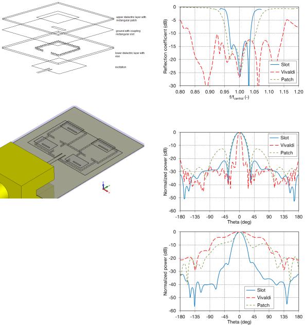
Figure 5: Multilayer schematics of a patch element fed by a SIW resonator via an aperture.
Figure 6: Patch array fed by SIW.
The array was designed to operate at 31 GHz. The feeding network consisted of two parallel SIW bandpass filters sharing a common cavity. The last cavity of each SIW filter was loaded by an aperture exciting a patch. The second SIW cavity was also loaded by an aperture exciting a patch to support radiation. The phase shift between serial patches was tuned to avoid the main lobe deflection. The filtering array reached the gain bandwidth 7.5 % (from 29.3 GHz to 31.8 GHz). The realized gain in the pass-band was 13.2 dB. Out of the pass-band, the realized gain decreased for more than 15 dB. In the pass-band, the total main lobe deflection was 2 ° in the E plane.
3 COMPARISON OF SIMULATIONS
Simulated reflection coefficients |S11| of all antenna arrays normalized to their central frequency are compared in Figure 7. Obviously, Vivaldi array has the widest bandwidth. The other arrays have comparable bandwidths about one-third.
The simulated radiation patterns of antenna arrays at their central frequencies are depicted in Figure 8. They indicate low side lobe level which does not exceed −20 dB in E-plane except the patch array. If we design larger antenna array we could suppress the side lobes better. The front-to-back ratios are below −20 dB. In the required frequency bands, the gains of the antenna array are within the range from 13 dB to
Figure 7: Frequency responses of reflection coefficient related to normalized frequency.
Figure 8: Normalized patterns at central frequencies; E-plane (top) and H-plane (bottom).
|
Slot |
Vivaldi |
Patch |
|
|
|
|
BWs11 [%] |
7.1 |
32.0 |
9.5 |
SLL E-plane [dB] |
<−20 |
<−20 |
<−12 |
F/B [dB] |
<−32 |
<−20 |
<−30 |
|
|
|
|
Gmin [dB] |
>20 |
>15 |
>13 |
Table 2: Simulated parameters of developed antennas.
20 dB. Table 2 summarizes the radiation parameters of the antenna arrays at operational frequencies.
450
4 |
EXPERIMENTAL VERIFICATIONS |
5 |
CONCLUSIONS |
Properties of simulated antenna arrays were |
The designs of a three different concepts of compact |
||
experimentally verified to demonstrate validity of |
antenna arrays using substrate integrated waveguides |
||
comparisons presented in Section 3. |
technology were presented in the paper. Feeding part |
||
|
In order to verify the presented design of the |
of the antenna arrays are based on SIW which makes |
|
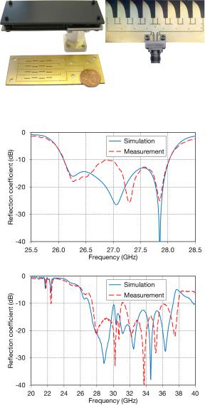
antenna arrays experimentally, we fabricated a small- |
the antennas low-profile, compact size, low-cost, and |
||
scale slot array consisting of 4×4 slots and Vivaldi |
easy to fabricate. |
||
antenna array (see Figure 9). |
|
All designed antennas have good radiation |
|
|
Figure 10 shows frequency response of reflection |
parameters. The antennas differ in the type of |
|
coefficient at the antenna inputs. Obviously, |
radiators and thus in use. |
||
simulations and measurements show acceptable |
|
The slot antenna array was designed for point-to- |
|
agreement. |
point wireless communication. The Vivaldi antenna |
||
|
The patch array is under construction. The |
could be used for microwave imaging, detection of |
|
prototype of the antenna and results of measurements |
buried objects, non-destructive testing and tracking. |
||
will be presented at the conference. |
And the patch antenna array as the filtering antenna |
||
|
|
could be used in communication systems with |
|
|
|
sensitive receivers requiring bandpass filters at the |
|
|
|
front-end. |
|
Figure 9: Prototypes of the slot array and the Vivaldi array.
Acknowledgments
Research described in this paper was financially supported by the Czech Science Foundation under grant no. P102/12/1274. Research is a part of the COST Action IC1102 VISTA supported by the grant of the Czech Ministry of Education LD12012. Measurements were performed at SIX Research Center.
References
[1] Xu, F.; Wu, K., Guided wave and leakage characteristics of substrate integrated waveguide.
IEEE Transactions on Microwave theory and techniques, 2005, vol. 53, no. 1, p. 66–73.
[2] Mikulasek, T.; Puskely, J.; Lacik, J., Design of radome-covered substrate integrated waveguide slot antenna array, In Proceedings of the 7th European Conference on Antennas and Propagation EuCAP 2013, Gothenburg (Sweden): EurAAP, 2013, p. 1437–1441.
[3] Puskely, J.; Mikulasek, T.; Raida, Z., Design of a compact wideband antenna array for microwave imaging applications, Radioengineering, 2013, vol. 22, no. 4, p. 123–131.
[4] Wolansky, D.; Hebelka, V.; Raida, Z., Two-pole filtering antenna for body centric communications, In Proceedings of Loughborough Antennas and Propagation Conference LAPC 2013, Loughborough (UK), 2013, p. 221–224.
Figure 10: Frequency response of reflection coefficient at the input of 4×4 slot array (top) and
8-element Vivaldi array (bottom).
451