

диафрагмированные волноводные фильтры / ea495a32-967f-4ebe-90fd-d79c5913c8df
.pdfPatch Antenna with Integrated Bandpass Filter
Xiaobang Shang1, Michael J. Lancaster2
School of Electrical, Electronic and Computer Engineering, the University of Birmingham, B15 2TT, U.K.
Email:1x.shang@bham.ac.uk,2m.j.lancaster@bham.ac.uk
Abstract
This paper presents a novel antenna that includes filtering functionality. The design approach is based on directcoupled resonator filter theory. In this approach, the filter can be integrated into the antenna itself using the antenna resonant elements as the resonators of the filter. The design principle can be applied to any desired frequency and physically realised using different types of antenna structures. In this example, a rectangular patch antenna integrated with four conventional square open-loop resonators is designed using a single layer microstrip to verify this antenna-filter design approach. In order to preserve the filter’s characteristic, the radiation quality factor of the patch antenna is chosen the same as the external quality factor of the filter, and the coupling between the patch antenna and the last open-loop resonator is calculated using the theory for two conventional coupled resonators. The simulation results demonstrate this filter antenna design approach works well.
1 Introduction
Conventionally, in a communication system, the antenna module is directly connected to a filter to remove spurious out of band signals using the traditional 50 interfaces. However, an extra matching circuit is required between the antenna and filter to address the mismatching problems such as a degraded filter performance, especially at band edges, and an increased insertion loss of the overall systems [1]. Recently, in an effort to reduce the weight and size of the RF front-end system and in the pursuit of improved performance, there is an increasing interest in integrating the antenna and filter in a single compact module which has both the filtering and radiating functions, such as the work presented in [1]-[7]. These reported antenna filter integration work generally follow two approaches: (i) introducing external matching network between the antenna and filter; (ii) integration of the matching in the antenna element itself by discovering suitable connection geometry [6].
In this work, the antenna-filter is designed by following the conventional coupled-resonator filter design theories, and the last resonator of the bandpass filter is replaced by a resonating patch antenna, which means the patch antenna achieves not only the radiation function but also acts as a resonator of the filter structure. This antenna filter integration approach based on coupled resonator filter theory was first reported in [6].
In order to preserve the filter characteristics, the radiation quality factor of the antenna is chosen as the external quality factor of the filter. The coupling between the antenna and the last open-loop resonator is characterised using coupling theory between two coupled resonators. This approach has consequences on the bandwidths available for the antenna-filter, but there are similar limitations in conventional matching.
2 Design of the Filter
A fifth order filter based on square open-loop resonators is designed to have a centre frequency of 3 GHz, a passband return loss of 20 dB and a fractional bandwidth of 3.4%. From these specifications, the filter’s corresponding coupling coefficients and external quality factors can be determined as: k12=k45=0.0295, k23=k34=0.0216, Qe1=Qe5=28.57 [9]. This filter is designed based on a 2.54 mm thick substrate with a relative dielectric constant İr of 9.8. The physical dimensions of the input/output coupling irises are determined by simulating a structure as shown in Fig. 1 (a) in Sonnet [8]. Each of square open-loop resonators is actually a folded half-wavelength resonator. For the fundamental mode, the maximum electric field exists at the open gap of the resonator, while the maximum magnetic field occurs at the opposite side [9].

Fig. 1 External quality factor calculation. (a) Simulated model in Sonnet for the external Q determination. (b) Simulation results of the structure.
Fig. 1 (b) shows the simulation results of the structure given in Fig. 1 (a). From the simulation results, the external quality factor can be calculated directly from the resonant frequency (f0) and the 3 dB bandwidth (¨f), as stated below [9]:
f0 |
(1) |
Qe 'f |
The resonant frequency of the simulated structure varies with the length of the open-loop resonator (L) and the gap s, as indicated in Fig. 1 (a). L and s should be adjusted to ensure that the simulated model is resonating at the filter’s centre frequency. The required external Q can be achieved by altering the tapping position p. To employ equation (1) for the external Q calculation, the coupling from the feed line on the right side must be very weak. The coupling coefficient is determined from the simulation of a structure as shown in Fig. 2 (a). The ports need to be weakly coupled to resonators for this approach to work. A sketch of S21 is given in Fig. 2 (b). The split resonant frequency can be observed from the two peaks of S21 and the nature of the coupling (electric or magnetic) can be determined from the phase information of S21.
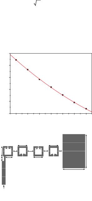
Fig. 2 (a) Two weakly coupled open-loop square resonator structure, and their simulation results (b). (c) Coupling coefficients as a function of coupling gap d for the structure in Fig. 2 (a).
The relationship between the coupling coefficient k and the resonant frequencies (f1, f2) is given by [9]
k |
f |
22 |
f12 |
(2) |
|
f22 |
f12 |
||||
|
|
||||
For the simulated structure, an increase of the coupling gap d leads to a reduction of the coupling coefficient. The middle frequency of these two resonant peaks (i.e. (f1+f2)/2) also varies with L. For synchronous tuned filter, where all the resonators have the same resonant frequency, the middle frequency of these two peaks should in accordance

with the filter centre frequency. The simulations are carried out for a range of coupling gaps d, and a fitted curve is obtained from these points, as shown in Fig. 2 (c). The required resonator gaps to achieve the desired coupling coefficients for the filter can be read directly from the constructed curve. These in conjunction with the input/out coupling dimensions are very good initial solution and can be further optimised using Sonnet. The final design of this filter with optimised dimensions is given in Fig. 3. Its corresponding S parameter results are given in Fig. 4.
Fig. 3 Layout of the fifth order Chebyshev bandpass filter. l1=6.34, l2=6.29, l3=6.29, d1=2.97, d2=3.64, s1=0.39, s2=0.34, s3=0.35, t1=1, t2=2.4, p=4.63, lf=3, Unit: mm.
3 Design of Antenna Filter
The approach described in Section 2 is followed to design the antenna-filter. The external quality factor of the input port is still achieved through tapped line, whereas at the other port it is accomplished through radiation of the patch antenna. In other words, if the radiation quality factor of the patch antenna matches the external quality factor of the filter, the filter characterises would be preserved. Since the antenna filter has the same specification as the filter, in terms of centre frequency and bandwidth, therefore the fifth resonator shown in Fig. 3 is replaced by a patch antenna and dimensions of the fourth resonator has been slightly altered to factor in the effect of the patch antenna. The dimensions of resonators 1 to 3 remain the same as the filter structure shown in Fig. 3.
S Parameter, dB
0 


-10
-20
-30
-40 |
S11(Filter_Sonnet) |


 S21(Filter_Sonnet)


S11(Filter antenna_CST)
2.85 |
2.90 |
2.95 |
3.00 |
3.05 |
3.10 |
3.15 |
Frequency, GHz
Fig. 4 Simulation results of the fifth order open-loop ring resonator filter and the antenna with filter.
(a) (b)
Fig. 5 (a) Simulated structure in CST [10] for radiation quality factor determination. (b) Configuration of the simulated structure for the coupling coefficients between the open-loop square resonator and the patch antenna.
The structure shown in Fig. 5 (a) is simulated to extract the radiation quality factor, in order to simply the problem, the loss of the substrate dielectric and coating metal is not taken into consideration in the simulations. Reference [11] introduced a one-port measurement method for calculating the unloaded Qu (i.e. Qr ) and external Q (i.e. Qe1) of a microwave resonator. This technique is employed in this work to calculate Qr from the S11 simulation results of the structure shown in Fig. 5 (a). The relationship between these quality factors is expressed below.
QL |
|
1 |
|
(3) |
|
1 |
|
1 |
|||
|
|
||||
|
Q |
Q |
|
||
|
|
|
|||
|
e1 |
|
r |
|
Additionally, the radiation quality factor Qr of a rectangular patch antenna can also be approximately evaluated as follows [12]
Qr |
c |
He |
(4) |
|
4 fr |
h |
|||
|
|
where h is the thickness of the dielectric substrate, fr is the operating frequency, c is the velocity of electromagnetic waves in free space and İe is the effective dielectric constant of the substrate. Qr obtained from equation (4) is consistent with the value calculated using equation (3) from the simulation results in CST.
The structure as shown in Fig. 5 (b) is simulated in CST to determine the separation between the patch and the fourth open-loop resonator. Similarly, a fitted curve is constructed, as shown in Fig. 6, from which the required coupling gap d to achieve k45 could be extracted.
Coupling coefficient, k
0.07
0.06
0.05
0.04
0.03
0.02
1.0 |
1.2 |
1.4 |
1.6 |
1.8 |
2.0 |
2.2 |
|
|
|
d, mm |
|
|
|
Fig. 6 Coupling coefficients between the patch and the open-loop resonator as a function of coupling gap d for the structure shown in Fig. 5 (b).
Fig. 7 Layout of the antenna filter structure, p=4.63, lf=3, t1=1, t2=2.4, l1=6.34, s1=0.39, d1=2.97, l2=6.29, s2=0.34, d2=3.64, l3=6.29, s3=0.35, d3=3.384, d4=2.39, lp=14.211, wp=21.5, Unit: mm.
Fig. 7 shows the configuration of the antenna-filter and the final dimensions. Fig. 4 shows the simulation results associated with the dimensions given in Fig. 7. As shown in Fig. 4, the antenna filter responses exhibit five reflection zeros. This demonstrates that the patch antenna is operating as a resonator of the filter structure. A deviation from the fifth pole filter’s response is observed and this is believed to be attributed to the open-loop resonators and patch antenna radiation, since the antenna-filter is simulated in CST with open add space boundaries. As pointed out in [13], the radiation of resonators would result in degradation in the roll-off at the lower band of the filter’s performance. The unwanted cross coupling between resonators, which is not accounted for in the design approach presented, may also have effect on the antenna-filter’s final responses.
(a) (b)
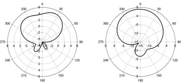
Fig. 8 (a) Simulated H-plane radiation patterns at 3 GHz. (b) Simulated E-plane radiation patterns at 3 GHz.
For this antenna filter, the simulated H-plane and E-plane radiation patterns at 3 GHz are shown in Fig. 8. According to CST simulations, the maximum gain in the H-plane is about 4.9 dBi at 30o, whereas the maximum gain in the E-plane is about 3.9 dBi at 0o.
References
[1]Chuang C. T., Chuang S. J.: ‘Synthesis and Design of a New Printed Filtering Antenna,’ IEEE Trans. Antennas and Propaga., 2011, 59, (3), pp. 1036-1042.
[2]Cheng H., Yusuf Y., Gong X.: ‘Vertically Integrated Three-Pole Filter/Antennas for Array Applications,’ IEEE Antennas and Wireless Propaga. Lett. , 2011, 10, pp. 278-281.
[3]Yusuf Y., Gong X.: ‘A New Class of 3-D Filter/Antenna Integration with High Quality Factor and High Efficiency,’ in 2010 IEEE MTT- S International Microwave Symposium Digest, pp. 892-895.
[4]Nova O., Bohorquez J. C., Pena N. M., Bridges G. E., Shafai L.: ‘Filter-Antenna Module Using Substrate Integrated Waveguide Cavities,’ IEEE Antennas and Wireless Propaga. Lett. , 2011, 10, pp. 59-62.
[5]Queudet F., Pele I., Froppier B., Mahe Y. and Toutain S.: ’Integration of Pass-Band Filters in Patch Antennas,’ in the 32nd European Microwave Conference, 2002, pp. 685-688
[6]Yang Y., Lancaster M. J.:’ Waveguide Slot Antenna with Integrated Filters,’ in the 32nd European Space Agency Workshop, 2010
[7]Nova O. A., Bohorquez J. C., Pena N. M.: ‘ An approach to filter-antenna integration in SIW technology,’ in 2011 IEEE Second Latin American Symposium on Circuits and Systems(LASCAS), pp. 1-4.
[8]em user’s manual, Sonnet Software, Inc., Version 12.52, 2012.
[9]Hong Jiasheng, Lancaster M. J.: ‘Microstrip Filters for RF/Microwave Applications’ (New York: John Wiley & Sons)
[10]CST Microwave Studio: CST Gmbh, Germany, 2006
[11]Kwok R. S., Liang J.F.: ‘Characterization of High-Q Resonators for Microwave-Filter Applications,’ IEEE Trans. Microw. Theory and Tech., 1999, 47, (1), pp. 111-114.
[12]Bahl I.I., Bhartia P.: ‘Microstrip Antennas’ (Artech House Inc., 1980)
[13]Cameron R. J., Kudsia C. M., Mansour R. R.: ‘Microwave Filters for Communication Systems: Fundamentals, Design and Applications’ (Wiley 2007). Chapter 14