

диафрагмированные волноводные фильтры / d2d99c7a-8e33-4365-bb62-70873c4f1ae4
.pdfAn Original Resonant Y-Junction for Compact Waveguide Diplexers
Simone Bastioli1, Luca Marcaccioli2, Roberto Sorrentino1
1University of Perugia, DIEI, Via G. Duranti 93, 06125 Perugia, Italy 2 RF Microtech s.r.l., Via G. Duranti 93, 06125 Perugia, Italy
Abstract — This paper presents an innovative resonant Y-junction for the design of compact rectangular waveguide diplexers. The junction contains an elliptic ridge which serves as common dual-mode resonator for both channel filters. The junction itself constitutes therefore the first resonators of the filters, thus allowing for considerable size reduction with respect to the conventional diplexer implementation. The orientation of the input branch and the insertion of irises and ridge taps are used to control the coupling coefficients within the junction. An X-band diplexer employing the proposed junction in combination with H-plane cavity filters has been designed, manufactured, and successfully tested.
Index Terms — Bandpass filters, diplexers, rectangular waveguides, waveguide filters, waveguide junctions.
I. INTRODUCTION
Diplexers are widely used in microwave and mm-wave communications to separate/combine two frequency channels sharing a common feeding line. In many applications, channels isolation, insertion loss and power handling are stringent electrical requirements. Waveguide technology is especially recommended to minimize the loss occurring between the antenna and the front-end, thus improving the radio-link performance. On the other hand, the waveguide implementation makes the diplexer one of the most cumbersome structures of the whole RF equipment. Therefore, geometrical and size constraints are further fundamental requirements.
Typical diplexer architectures employ a three-port junction between two separately designed filters [1]. Several H-plane and E-plane three-port junctions have been proposed [2]-[5], each of them having its specific properties in terms of electrical and mechanical features. The filters are usually connected at a proper distance from the junction, in such a way as to optimize the diplexer performance and to ease the design procedure [6]. In such implementations, however, the size of the whole diplexer is larger than the sum of the two filters.
In this work an original resonant three-port junction is proposed providing a compact solution for rectangular waveguide diplexers. The junction itself constitutes the first resonators of both channel filters; in this way the diplexer size is reduced to less than the sum of the two separate filters.
The structure of the junction is shown in Fig. 1: it consists of an H-plane Y-junction which contains at its center an elliptic ridge resonator similar to those introduced in [7], [8];
such a ridge serves as a common dual-mode resonator for the channel filters [9]. This junction can easily be used in connection with most waveguide filter architectures.
|
|
2 |
|
dH |
|
b |
|
dL |
|
|
|
1 |
g |
3 |
a |
|
|
Fig. 1. The resonant Y-junction.
The basic properties of the resonant Y-junction along with the design and experimental results of a diplexer based on the proposed approach are presented in this paper.
II. THE RESONANT Y-JUNCTION
The elliptic ridge resonator is the key element of the proposed junction. The ridge resonator concept has recently been introduced in [7], where rectangular ridges have been used as open-ended half-wave resonators embedded in a rectangular waveguide. The concept has been then extended to square ridge resonators to obtain dual-mode structures [8].
Similarly to the square ridge resonator, the elliptic ridge supports two modes resonating along orthogonal directions within the gap g between the ridge and the opposite waveguide wall. When the gap is sufficiently smaller than the rectangular waveguide height, the electromagnetic field therein confined is distributed as a quasi-TEM field. The ridge behaves indeed as a dual-mode open-ended parallel plate resonator embedded into the waveguide junction, and its resonant frequencies fL and fH can be approximated as:
f L ≈ |
c |
, |
f H |
≈ |
c |
(1) |
2d L |
2d H |
|||||
|
|
|
|
|
|
where c is the free-space light speed, while dL and dH are the major and the minor axes of the elliptic ridge, respectively. Fig. 2 shows the electric field distribution of the two resonant modes. As expected, due to the non pure TEM behavior of the field and to the fringing field effects, the resonant frequencies may differ from those in (1), especially when the gap of the ridge increases.
978-1-4244-2804-5/09/$25.00 ♥ 2009 IEEE |
1233 |
IMS 2009 |
|
2 |
x |
2 |
|
|
||
|
|
y |
z |
+ |
|
|
- |
- |
3 |
3 |
|
|
|
|
+ |
1 |
|
|
1 |
|
|
(a) |
(b) |
Fig. 2. Electric field Ey distribution (CST MWS): (a) mode resonating at fL along the major axis; (b) mode resonating at fH along the minor axis.
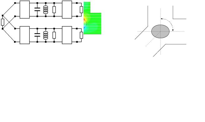
A top view of the resonant Y-junction is shown in Fig. 3: the input branch, referred to as port 1, is slant with respect to both output branches (namely port 2 and 3), that are orthogonal one to each other. The ellipse axes are oriented along the output branch axes. Because of the input branch orientation (referred to as θ in Fig. 3), the fundamental TE10 mode at port 1 excites both resonant modes. Each resonant mode, for symmetry reasons, can only excite the TE10 mode of the output branch whose axis is directed along the mode resonance. Specifically, the resonant mode shown in Fig. 2a
can only excite the TE10 mode at port 3, whereas the resonant mode shown in Fig. 2b excites the TE10 mode at port 2. Each output port can therefore be assigned to a prescribed frequency channel. As expected, a rectangular ridge would also have the same effect; nevertheless, the elliptic shape presents no corners and is therefore expected to be more suited to interface with the slant input branch.
The resonant Y-junction can be described using the equivalent circuit of Fig. 4. The load GS represents the fundamental TE10 mode of port 1; similarly, the loads GL(H) and GL(L) represent the fundamental mode at port 2 and 3. The parallel resonators L(L)C(L) and L(H)C(H), along with the frequency independent suscettances B(L) and B(H), correspond to the ridge resonant modes. As commonly done in filtering networks, B(L) and B(H) are introduced to account for possible shifts of the resonant frequencies fL and fH, respectively. The admittance inverters JS1(L) and JS1(H) represent the coupling coefficients between the TE10 mode at port 1 and the ridge resonant modes; similarly, the admittance inverters J1L(L) and J1L(H) represent the coupling between the resonant modes and the TE10 mode at the corresponding output ports. The resonant Y-junction can therefore be used as a diplexer with first order channel filters.
For practical design, it is essential to control the coupling coefficients in the junction, i.e. the admittance inverters of the corresponding equivalent circuit. To this purpose, additional elements have to be added to the basic structure of the junction. As done in [7] for rectangular ridge resonators, inductive irises or ridge taps may be used to decrease or increase the coupling levels over a wide range.
Port 2 axis
90°
Port 3 axis
θ
Port 1 axis
Fig. 3. Top view of the resonant Y-junction.
|
C(H) |
L(H) |
B(H) |
Port 2 |
Port 1 |
JS1(H) |
|
J1L(H) |
G(H)L |
|
|
|
|
|
GS |
(L) |
(L) |
(L) |
|
|
C |
L |
B |
Port 3 |
|
JS1(L) |
|
J1L(L) |
G(L)L |
Fig. 4. Equivalent circuit of the resonant Y-junction.
In particular, two elements (irises or ridge taps) realized at the port 2 and 3 allow for independent control of the output coupling coefficients (J1L(H) and J1L(L)). In order to control the input coupling coefficients (JS1(H) and JS1(L)) it is necessary to add an element at port 1 as well as to work on the inclination θ of the input branch; while the introduced element increases or
decreases both input coupling coefficients, the angle θ is used to vary the ratio between the two coefficients. Specifically, as θ tends to 0 the coupling coefficient JS1(H) vanishes, because the mode of the elliptic ridge resonating along the minor axis is not excited by the TE10 mode at port 1 when θ =0. Similarly, as θ tends to π/2, JS1(L) vanishes.
Fig. 5 illustrates the resonant Y-junctions with inductive
irises (a) and ridge taps (b). In order to demonstrate the design flexibility given by these elements, Fig. 6 shows the responses of three different resonant junctions designed with WR-90 interconnections, resonating at fL=9.3 and fH=10.7 GHz: Fig. 6a and 6b show the utility of irises and ridge taps to realize narrowand wide-band responses, respectively. In these cases the bandwidth of the channel filters is the same, being the angle θ of the input branch at nearly π/4. Fig. 6c demonstrates the possibility to realize also channel filters having unequal bandwidths, obtained by properly varying the input branch orientation.
1234

(a) |
(b) |
Fig. 5. Resonant Y-junctions employing irises (a), and ridge taps (b).
2
3
1
(a)
2
3
1
(b)
2
3
1
(c)
Fig. 6. Full-wave simulations (HFSS) of three resonant Y-junctions: (a) narrow-band channels; (b) wide-band channels; (c) asymmetric channels.
III. DIPLEXER DESIGN
The resonant Y-junction can be used as first block of diplexers employing channel filters of arbitrary order.
The design is carried out starting from the equivalent circuit of Fig. 4; by replacing the loads GL(H) and GL(L) with the equivalent circuits of two channel filters (each starting from its second resonator), the equivalent circuit of a whole diplexer is obtained. As example, Fig. 7 illustrates the equivalent circuit of a diplexer employing third order filters.
|
H |
H H |
C |
H |
H |
H |
C |
H |
H |
H |
H |
|
C |
L B1 |
|
L B2 |
|
L |
B3 |
GL |
|||
GS |
KS1H |
K12H |
|
|
|
|
K23H |
|
|
|
K34H |
|
CL L B1L |
CL L B2L |
CL L B3L |
GLL |
|||||||
|
KS1L |
K12L |
|
|
|
|
K23L |
|
|
|
K34L |
Fig. 7. Equivalent circuit of a diplexer: the dotted boxes indicate the subcircuits corresponding to the resonant Y-junction and to the channel filters.
The diplexer equivalent circuit can initially be dimensioned with the values of two filters individually synthesized, and then optimized to compensate for filter interaction. The equivalent sub-circuits corresponding to the resonant Y-junction and to the channel filters can be extracted and their physical structure individually designed by means of fullwave simulators. Eventually, the structures are connected together and only a minor optimization is necessary to account for higher order modes effect and waveguide dispersion.
To demonstrate the validity of the approach, an X-band diplexer employing H-plane cavity filters has been designed and manufactured. The frequency channels have 250 MHz bandwidth around the frequencies fL=10.055 and fH=10.525 GHz. The return loss in both pass-bands is 20 dB, and the channel isolation is 60 dB. This is accomplished by using fifth order filtering functions with one transmission zero located above the pass-band (for the lower frequency channel filter) or below the pass-band (for the higher frequency filter).
The diplexer, designed in standard WR-90 (a=22.86 mm, b=10.16 mm), is shown in Fig. 8a. Both channel filters make use of iris-coupled cavities and have the same topology; a doublet made by a TE102 and a TE101 mode cavities connected in parallel is used to generate the transmission zero, as proposed in [10]. With this configuration, the transmission zero can be located either above or below the pass-band depending on the resonant frequencies of the two cavities. Observe that the coupling with the resonant modes of the elliptic ridge is adjusted by means of inductive irises, as discussed in Sec. II. Fig. 8b shows an equivalent diplexer design using a conventional Y-junction; the dashed boxes highlight the diplexer part which is replaced by the resonant Y-junction. The advantage in terms of compactness is evident.
The gap g of the elliptic ridge resonator is one third of the waveguide height b; the computed Q-factor at 10.5 GHz is 4000 considering aluminum surfaces (σAl=36 MS/m). Observe that waveguide cavities have a Q-factor of 6000 considering the same material and frequency; the resonant Y-junction will produce therefore only a modest increment of insertion loss with respect to the conventional diplexer configuration (for this design we computed roughly 0.03 dB of loss increment at both channel center frequencies).
The manufactured aluminum prototype is shown in Fig. 9. Fig. 10 shows the measurement results, obtained after a minor
1235

(a)
(b)
Fig. 8. (a) Structure of the designed diplexer; (b) comparison between diplexers using or not using the resonant Y-junction as first stage.
Fig. 9. Manufactured X-band diplexer with WR-90 interface.
tuning, along with the full-wave simulation (HFSS): as required, 20 dB of return loss within the pass-bands, as well as 65 dB channels isolation, have been obtained. The measured insertion loss is roughly 0.35 dB at both channel center frequencies (0.23 dB is the simulated insertion loss).
IV. CONCLUSIONS
A resonant Y-junction is proposed as an innovative solution for the design of compact rectangular waveguide diplexers. The key element is an elliptic ridge resonator: such a ridge behaves as a common dual-mode resonator for two channel filters. The resonant Y-junction can be used as the first block of rectangular waveguide diplexers: it integrates the first resonators of both channel filters, thus allowing for considerable size reduction with respect to the conventional diplexer implementations. Inductive irises, ridge taps, and the
Fig. 10. Comparison between measurement (solid lines) and HFSS simulation (dashed lines).
input branch orientation, enable the synthesis of both narrowand wide-band channel filters, as well as filters having unequal bandwidths. The excellent experimental results of a manufactured X-band diplexer validate the proposed junction.
REFERENCES
[1]J. Uher, J. Bornemann, U. Rosenberg, Waveguide Components for Antenna Feed Systems: Theory and CAD, Artech House, Boston – London, 1993.
[2]Y. Rong, H.-W. Yao, K. A. Zaki, T. G. Dolan, “Millimeter-wave Ka-band H-plane diplexers and multiplexers,” IEEE Trans. Microwave Theory & Tech., vol. 47, no. 12, Dec. 1999.
[3]J. M. Rebollar, J. R. Montejo-Garai, A. Ohoro, “Asymmetric H- plane T-junction for broadband diplexer applications,” IEEE AP-S Int. Symp. Dig., pp. 2032-2035, July 2000.
[4]Ke-Li Wu, H. Wang “A rigorous modal analysis of H-plane waveguide T-junction loaded with a partial-height post for wideband applications,” IEEE Trans. Microw. Theory & Tech., vol. 49, no. 5, May 2001.
[5]T. Shen, K.A. Zaki, T.G. Dolan, “Rectangular waveguide diplexers with a circular waveguide common port”, IEEE Trans. Microw. Theory & Tech., vol. 51, no. 2, pp. 578-582, Feb. 2003.
[6]A. Morini, T. Rozzi, “Constraints to the optimum performance and bandwidth limitations of diplexers employing symmetric three-port junctions,” IEEE Trans. Microwave Theory & Tech., vol. 44, no. 2, pp. 242–248, Feb. 1996.
[7]S. Bastioli, L. Marcaccioli, R. Sorrentino, “Waveguide Pseudoelliptic filters using slant and transverse rectangular ridge resonators,” IEEE Trans. Microwave Theory & Tech., vol. 56, no. 12, pp. 3129–3136, Dec. 2008.
[8]S. Bastioli, L. Marcaccioli, R. Sorrentino, “A novel class of
compact dual-mode rectangular waveguide filters using square ridge resonators,” 38th European Microwave Conference Proc., pp. 626-629, Oct. 2008, Amsterdam, The Netherlands.
[9]U. Rosenberg, “Multiplexing and double band filtering with common-multimode cavities,” IEEE Trans. Microwave Theory & Tech., vol. 38, no. 12, pp. 1862–1871, Dec. 1990.
[10]S. Amari, U. Rosenberg, “The doublet: a new building block for modular design of elliptic filters,” 32nd European Microwave Conference Proceedings, Oct. 2002, Milan, Italy.
1236