

диафрагмированные волноводные фильтры / 35ef9ed1-ec82-45bc-8e84-d4298f8bac1d
.pdfProceedings of the 46th European Microwave Conference
Transmission Zero Realization in E-Plane Filters by Means of I/O Resonator Tapping
Efstratios Doumanis1, George Goussetis2, J. Huurinainen2
1Nokia, Dublin, Ireland efstratios.doumanis@nokia.com
2Heriot Watt University, Edinburgh, United Kingdom g.goussetis@ieee.org
Abstract— A new topology for E-plane filters compatible with the traditional low-cost single metal insert in a split-block housing is proposed. Improved out-of-band rejection is achieved by virtue of the transmission zeros. The overall length of the input and output resonators is reduced by ~45%, resulting in saving the length of a resonator. A synthesis procedure is outlined. A 4pole filter is demonstrated that implements 2 out-of- band TZs. The technique is well suited to be combined with an extracted pole technique further improving the out-of-band characteristics of the filters. The same 4pole filter is then adopted to accommodate for extra 4 TZs by means of extraction. The simulated loss of the two 4 pole filter presented is 0.22 dB and 0.24 dB, respectively.
Keywords—e-plane; e-plane resonators; waveguide; filters; transmission zeros;tapping; extraction.
I. INTRODUCTION
E-plane direct-coupled filters is a well-established technology [1]–[5], for microwave and millimeter-wave applications. Their advantageous characteristics include low cost, low dissipation loss, direct design avoiding tuning, easy integration with other microwave elements. However the attenuation in the second stopband may often be too low and too narrow for many applications such as multiplexers. E- plane technology can easily incorporate ridge waveguide. The ridged waveguide filter configuration has been reported to achieve improved stopband performance [6]. Introducing ridges in the resonators of E-plane filters slightly improved the stopband performance within the same waveguide housing, but the improvement is limited [6]. An improved out-of-band rejection has been demonstrated in [7] by integrating bandstop structures into the coupling elements of the filters.
The out-of-band characteristics of the filters can be effectively improved by the generation of transmission zeros in the stopband [8]. Very stringent specifications in the port isolation between the transmit and receive bands in diplexer applications has led to the use of asymmetric filtering characteristics. They can be employed to reduce the number of required resonators to achieve the out-of-band rejection levels by placing finite transmission zeros in the opposite frequency bands. In, [9] a folded configuration is proposed that allows cross-coupling between the resonators in order to produce a pseudo-elliptic response, at the cost of fabrication simplicity. Transmission zeros by extraction were introduced in [10] by resonators printed on the same metal insert and within a uniform waveguide housing but this was at a cost of larger total length. More recently, 2nd order filters with parallel
coupled asymmetrical ridge waveguide resonators were demonstrated to produce selectively located transmission zeros [11].
II. OPERATION PRINCIPLE & DESIGN GUIDELINES
A simple technique has been utilized in coplanar waveguide technology in [12], and in planar bandpass filters in [13] to introduce transmission zeros in the stopband of the filters. In this contribution, we propose a simple implementation of this technique in E-plane technology. In this way two out-of-band transmission zeros by means of the input/output tap coupling of the first and last resonators of the filter can be generated. This is achieved by folding the first/last resonator and adjusting the length between the input excitation and the short-ended part of the resonator. TZs can be generated in the lower or upper stop-bands of the filter by properly choosing this length. Sharp cut-off is achieved by placing the transmission zeros close the passband. Asymmetric responses are obtained. Furthermore, employing the technique introduced in [10] for E-Plane filters, extra TZs are introduced by extraction.
A. TZ generation by Tapping into the I/O Resonators
This section describes the application of the tap coupling utilizing a single folded resonator. It is demonstrated that by fixing the overall length of the resonator and adjusting the position of the input tapping it is possible to maintain the frequency characteristics of the resonance and alter the frequency characteristics of the TZ. That way one can design the first and last resonators of a filter fixing the frequency of the resonators and choosing the frequency of the TZs independently.
A schematic layout of a single folded E-Plane resonator is shown in Fig. 1. The input of the structure is a waveguide port where its input impedance is normalized in a commercial fullwave EM simulator (Ansys HFSS) to a small value (0.02 Ohms) in order to achieve the required weak input coupling. The output weak coupling is achieved with a long septum. Fig. 2 plots the magnitude of the transmission coefficient for a single folded E-plane resonator with weak external coupling. By adjusting the position of the resonator that the tapping occurs, the same resonant frequency with different frequencies for the transmission zero is achieved. The overall length of the resonator remains fixed whereas the length of Lr1b as depicted in Fig. 1b reduces. The resonant frequency is at 8.70 GHz for all the 4 cases studied. The transmission zero frequency is shifted upwards from 9.26 to 9.48 GHz.
978-2-87487-043-9 © 2016 EuMA |
767 |
4 –6 Oct 2016, London, UK |
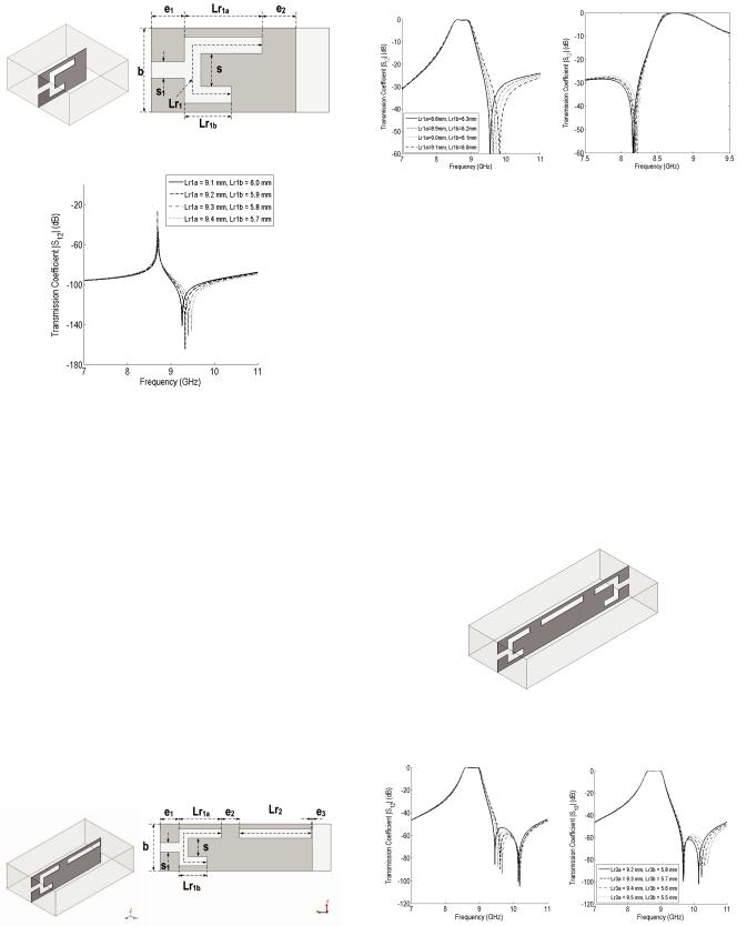
Fig. 1. Weakly excited single folded E-plane resonator and dimensions.
Fig. 2. Resonance characteristics of a single folded E-plane resonator. Simulated transmission coefficient with weak external coupling.
Employing the folded resonator as discussed in the previous section, the layout of a 2nd order filter is shown in Fig. 3. The first resonator is folded and the input coupling is achieved through tapping at a portion of the resonator’s length. Figure 4 plots the simulated performance of two 2nd order filters that exhibit an out-of-band TZ in the lower and upper passband. The filters are designed with same center frequency, ripple bandwidth and in-band return loss. The first design exhibits a transmission zero in the upper stopband of the filter and the second one in the lower stopband. The physical length of the folded resonator Lr1 as depicted in Fig. 3, is approximately 25% larger as compared to the length of the second resonator Lr2 resonating at the same frequency. The length in the filter that the first resonator occupies (i.e., Lr1a) stands for approximately ~45 % less as compared to a second resonator. Thus, by utilizing two of these resonators, at the input and output of a filter, it can save in length almost the entire length of a resonator. The results in Fig. 4 demonstrate that the tapping allows to generate and control a TZ in both the lower and upper stopband of the filter.
Fig. 3. Layout of the 2nd order filter topology with associated dimensions. The first resonator is folded and tapping is employed to generate a transmission zero.
Fig. 4. Simulated response of the 2pole filter with (left) a TZ at the upper stopband and (right) at the lower stopband; parametric study of the length of the first resonator (left) for the upper band TZ and of the first resonator (right) for the lower band TZ. This graph demonstrates that the tapping allows to generate and control a TZ in both the lower and upper stopbands of the filter.
B. TZ generation and independent control
Figure 5 shows the configuration of a 3pole filter with the first and last resonators in folded form. This configuration is capable of generating two out-of-band TZs by means of tapping at the first and last resonators. A parametric study of the length of the first resonator (left) low frequency TZ and of the last resonator (right) high frequency TZ is conducted. Figure 6 shows the simulated performance of the 3rd order filter with the two transmission zeros by tapping of the study and demonstrates the independent control of the frequency of each transmission zero. As shown in Fig. 6 (left), the high frequency TZ is kept fixed whereas the high frequency TZ is shifted. The situation is reversed in Fig. 6 (right). The filters are designed with same center frequency, ripple bandwidth and in-band return loss.
Fig. 5. Layout of the 3rd order filter topology with input and output folded resonators and tapping into both I/O resonators.
Fig. 6. Simulated performance of a 3rd order filter with two transmission zeros by tapping (Fig. 5); parametric study of the length of the first resonator (left) low frequency TZ and of the last resonator (right) high frequency TZ. Independect control of the frequency of each transmission zero.
768
III. DESIGN EXAMPLES
Here we explain the design method of band-pass filters composed of open-ended half-wavelength resonators applying the pole generation technique mentioned above. Basic design methodology is the same as conventional E-Plane filter design [3]. The physical dimensions of the filter are derived based on the synthesis process. The following step is to decide the positions of the tap coupling and the lengths of the coupled lines in accordance with the desired frequencies of the attenuation poles. In the next step, the physical length of the folded resonators is derived to be approximately 25 % greater than the length of the middle resonators. Subsequently, following the results shown in Figs. 1 and 2 the design for a fixed frequency (centre frequency of the filter) and the frequency of TZ follows. This procedure is followed in the next two examples.
A. Two pole filter with TZ below and above the passband
This example demonstrates that the proposed technique is capable of generating TZs at both sides of the passband. Two 2pole filters are designed. The filters are designed with same center frequency, ripple bandwidth and in-band return loss. Figure 7 demonstrates the simulated response of the two design examples. By adjusting the relevant position of the tapping to the first folded resonator, the frequency of the TZ can be positioned both in the upper and lower stopbands.
(a)
(b)
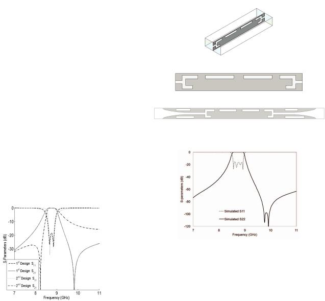
Fig. 8. Fig 8. Layout of the 4th order filter topology (top) Perspective view (bottom) Side view
Fig. 7. Simulated performance of the two 2nd order filter designs.
B. Four pole filter with TZs by tapping
Fig 8a shows the layout of the 4th order filter with tapping at the input and output resonators. The filter has been designed to have two TZs at the upper passband to increase the selectivity. This scenario suits well a duplexer scenario where the second duplex filter is positioned in frequency at the upper side of the band. Fig. 9 shows the simulated performance of
the filter. There are two TZs at frequencies of fTZ1=9.77 GHz and fTZ2=9.92 GHz. The analysis does not include loss. The
simulated in-band insertion loss of the filter with a copper septum (0.1 mm thick) is 0.22 dB.
Fig. 9. Simulated performance of the 4th order filter with two TZs at the upper stopband of the filter.
C. Four pole filter with TZs by tapping and extraction
Figure 8c shows the layout of the 4th order filter with tapping at the input and output resonators and the extra portion that includes the resonators for extraction. The filter has been designed to have two TZs by tapping at the upper passband to increase the selectivity and an extra 4 TZs by extrapolation. This extra 4 TZs are positioned two in the lower stopband and two in the upper passband. This scenario suits well most of the asymmetric filtering scenarios since there are numerous TZs placed on each side of the passband and can assist in increasing the rejection levels at any frequency around the main passband. Fig. 9 shows the simulated performance of the filter. There are two TZs at frequencies of fTZ1=9.78 GHz (9.77 GHz) and fTZ2=9.88 GHz (9.92 GHz). The additional 4 TZs are fTZ=7.54 GHz, fTZ=7.84 GHz, fTZ=9.57 GHz and fTZ=10.38 GHz. The analysis includes loss. The simulated inband insertion loss of the filter with a copper septum (0.1 mm thick) is now 0.24 dB. In practice with minimum additional loss (as compared to the first 4 pole filter), this filter has a significantly improved rejection due to the extra 4 TZs. There is an optimization involved after the inclusion of the extra portion of the new filter. The new 4 pole filter demonstrates improved out-of-band performance. Figure 11shows the inband group delay of the filter and Fig. 12 shows the wideband
769

response of the filter. Following the notations in Figs. 1 and 3, the dimensions of the filter in Fig. 10 are given in Table 1.
Table 1: Dimensions of the filter in Fig. 10.
|
Symbol |
mm |
|
Lr1a, Lr1b |
9.282, 6.0 |
Filter |
Lr4a, Lr4b |
9.27, 5.8 |
Lr2, Lr3 |
16.585, 16.585 |
|
Dimensions |
e2, e3, e4 |
4.609, 5.743, 4.591 |
|
s1 |
2.0 |
|
matching section length |
21.7 |
|
a, b |
22.86, 10.16 |
Fig. 10. Simulated response of the 4th order filter with two TZs by tapping and extra 4 TZs by extrapolation. The TZs are placed by extrapolation are positionoed both ways of the pass-band, 2 below and 2 above.
Fig. 11. Simulated group delay response of the 4th order filter with two TZs by tapping and extra 4 TZs by extrapolation.
Fig. 12. Simulated wideband response of the 4th order filter with two TZs by tapping and extra 4 TZs by extrapolation.
IV. CONCLUSION
Inline E-plane filters with selectively located transmission zeros by means of I/O resonator tapping are proposed. Numerical results are presented to validate the proposed structure. Parametric curves and a synthesis procedure for the proposed filters is outlined. By utilizing the proposed technique, two TZs can be generated and the length of an entire resonator can be saved of the overall filter length. The proposed topology is compatible with the standard single thin all-metal insert in a split-block housing and therefore maintains the low-cost characteristics and compatibility with traditional circuit fabrication techniques. Additional TZs are included by means of extrapolation that makes the proposed filters attractive solution due to the low-cost, low-loss and high performance.
REFERENCES
[1]Vahldieck R., Bornemann J., Arndt F., Grauerholz D., “W-Band Low- Insertion-Loss E-Plane Filter”, IEEE Transactions on Microwave Theory and Techniques, pp. 133 -135, Vol. 32, Issue 1, Jan 1984.
[2]Jia-Sheng Hong, “Design of E-plane filters made easy”, IEE Proceedings Microwaves, Antennas and Propagation (H), pp. 215-218, Vol. 136, Issue 3, June 1989.
[3]D. Budimir, G. Goussetis, “Design of asymmetrical RF and microwave bandpass filters by computer optimization”, IEEE Transactions on Microwave Theory and Techniques, pp. 1174 -1178, Vol. 51, No. 4, April 2003.
[4]G. Goussetis and D. Budimir, “Novel Periodically Loaded E-plane Filters”, IEEE Microwave and Wireless Components Letters, pp 193195, Vol.13, No. 6, June 2003.
[5]G. Goussetis, A.P. Feresidis, D. Budimir, and J.C. Vardaxoglou, “Compact Ridge Waveguide Filter with Parallel and Series Coupled Resonators,” Microwave and Optical Technology Letters, Vol. 45, No.1, pp. 22 -23, April 2005.
[6]D. Budimir, “Optimized E-plane bandpass filters with improved stopband performance,” IEEE Trans. Microwave Theory and Techniques, Vol. 45, No. 2, pp. 212-220, Feb. 1997.
[7]Z. Xu, J. Guo C. Qian and W. Dou, “Broad-band E-plane Filters With Improved stopband performance,” IEEE Microwave and Wireless Comp. Letter, Vol. 21, No. 7, pp. 350-352, Jul. 2011.
[8]Jia-Sheng Hong and M.J Lancaster, Microstrip filters for RF/Microwave applications, Wiley, ISBN 0-471-38877-7, 2001.
[9]E. Ofli, R. Vahldieck, and S. Amari, “Novel E-plane filters and diplexers with elliptic response for millimeter-wave applications,” IEEE Transactions on Microwave Theory and Techniques, vol. 53, no. 3 Part 1, pp. 843–851, 2005.
[10]D. Young, and I. Hunter, “Integrated E-Plane Filters with Finite Frequency Transmission Zeros,” proc. IEEE 24th European Microwave Conference, (Volume:1 ) Sep. 1994, pp 460-465.
[11]R. Lopez-Villarroya, G. Goussetis, J.S. Hong, J.L. Gomez-Tornero, “E- plane Filters with Selectively Located Transmission Zeros” 38th European Microwave Conference Proc, pp. 763-766, Oct. 2008.
[12]K. Wada, and I. Awai, “A Ȝ/2 CPW resonator BPF with multiple attenuation poles and its miniaturization,” IEEE Antenna Propag. Symp. Dig., pp 1139-1142, Jul. 1999.
[13]M. Matsuo, H. Yabuki and M. Makimoto, “The design of a halfwavelength resonator BPF with attenuation poles at desired frequencies,” IEEE Antenna Propag. Symp. Dig., pp 1181-1184, Jul. 2000.
770