

диафрагмированные волноводные фильтры / f63951d2-ebe6-468b-8fce-e4d11c12351e
.pdfE-PLANE FILTER DESIGN FOR SPACE APPLICATIONS WITH ADVANCED AND
STRINGENT PERFORMANCE REQUIREMENT
R. Lopez-Villarroya, G.Goussetis, J.-S. Hong
Heriot-Watt University, EH14 4AS, Edinburgh, UK, emails: G.Goussetis@hw.ac.uk, J.Hong@hw.ac.uk, rl49@hw.ac.uk
ABSTRACT
In this paper we will present our recent advances in E-plane filters with advanced performance characteristics. In particular, we are proposing different configurations, that produce size reduction, dispersion compensation and transmission zeros at finite frequencies. E-plane triplet filters, can produce finite transmission zeros without any further fabrication complexity. The concept is based on simultaneous series and parallel coupling of the resonators in a triplet. A single triplet has been demonstrated to produce a finite transmission zero, which can be employed for sharp roll-off. Larger order filters are proposed to be fabricated as series cascade of triplets. E-plane filters with slow wave periodically loaded resonators have also been produced. The structure maintains the fabrication simplicity of all-metal split-block housing but the periodic loading with ridges can reduce the length of the resonator. Following a proof of concept filter with two resonators, a 5-resonator prototype filter has been successfully designed, fabricated and measured. Numerical techniques for the design of this type of filter will be presented.
INTRODUCTION
E-plane filters configurations have received increased attention in the recent past. Adding metallic inserts centred in the E-plane of a split block waveguide housing is a well-established technique for realising low-cost and mass producible microwave configurations, such as bandpass filters and low-pass filters [1-13]. In this paper we summarise our recent activity in the area of E-plane filters. In particular we present analysis of a periodically loaded E-plane waveguide and its applications in lowpass filters, dispersion compensated waveguides as well as miniaturised bandpass filters. Moreover, we present recent results on novel E-plane bandpass filters topologies that allow selective location of transmission zeros at finite frequencies.
PERIODICALLY LOADED E-PLANE FILTERS
Electromagnetic Band Gap (EBG) structures have received increased attention in recent years. EBG structures have a frequency band in which no electromagnetic mode can propagate. Furthermore, at other frequencies, EBG structures have the property of reducing the phase velocity of EM modes, according to the slow wave effect. Typically, the EBG property emerges by virtue of periodic reactive loading of the guiding structure. In the general case, adopting an equivalent circuit approach, simple loads can be inductive (L), capacitive (C) or resonant (both L and C), in either series or shunt topology [1]. E-plane split-block housing topology offers a suitable platform for the realisation of waveguide loaded with periodic resonant loads, in the form of thin ridges (Fig. 1).

t
y |
-z |
b |
|
|
x |
|
|
a |
|
Lr |
Lw |
uc |
s |
|
|
b |
y |
z |
|
D |
|
|
Fig. 1: Layout of the E-pane EBG waveguide.
Propagation in this type of electromagnetic band gap waveguides is conveniently studied by an eiganevalue analysis of the unit cell, which assumes a transmission line of infinite length. A method involving a mode-mathcing full wave model and application of Floquet theorem for the boundary conditions at the two ends of the unit cell was described in [1], A simple transformation that brings the eigenvalue problem into its canonical form is proposed; allowing for fast and efficient calculation of the eigenvalues. Moreover, this technique directly yields the decomposition of the Floquet modal solutions into forward and backward propagating TE and TM modes in the hollow waveguide.
A. LOWPASS FILTERS
Electromagnetic band gap waveguides can be employed to produce a lowpass filters. The band gap corresponds to the stopband, provided that matching with the input and output is achieved. In order to achieve matching, in [1] the length of the first and last ridge waveguide section was empirically adjusted for an example of a lowpass filter with cutoff at 11.5GHz. A simple optimisation using a full-wave mode matching model for the finite structure was obtained. The full-wave response is reproduced in Fig. 2. It was demonstrated that a transmission zero is introduced as a result of the periodic loading resonance. This is identified in Fig. 3, as the sharp minimum at about 14.2GHz. In the eigenvalue solution, the transmission zero is identified by a sharp peak in the attenuation coefficient, α, in the band gap. The theoretical attenuation as calculated by e-αz is compared in Fig. 3. It is interesting to note that the attenuation coefficient derived for the infinite structure predicts to a good extend the response of the finite structure.
0.5 |
|
0.3 |
|
|
beta |
0.25 |
|
|
beta |
|
|
|
|
|
|
|
alfa |
0.2 |
|
|
|
|
|
0.25 |
|
0.15 |
|
Propag.(norm.)Const. |
|
0.1 |
Atten.(nep/mm)Coeff. |
|
0.05 |
||
|
|
||
0 |
|
0 |
|
5 |
10 |
15 |
|
Frequency (GHz)
Fig. 2, Full-wave dispersion diagram for periodically loaded X- band waveguides with ridge waveguide discontinuity (Lw=6 mm, Lr =2 mm, s =1 mm). Thickness of metal insert is t=0.1 mm.
Frequency (GHz)
|
8 |
10 |
12 |
14 |
16 |
|
0 |
|
|
|
|
(dB) |
-20 |
|
|
|
|
|
|
|
|
|
|
S-parameters |
-40 |
|
|
|
|
-60 |
|
Theor Atten. |
|
|
|
|
|
|
|
|
|
|
|
|
S11 (Theory) |
|
|
|
-80 |
|
S12 (Theory) |
|
|
Fig. 3, Simulated mode matching results for a fifth-order low-pass prototype. Dots shows S12 as estimated from the attenuation constant of the infinite structure.

To demonstrate an application of the proposed waveguide, this lowpass filter has been integrated with an E- plane bandpass filter in order to suppress the spurious harmonic resonance of the latter. A prototype has been fabricated and tested. The measured response and a photograph of the prototype are shown in Fig. 4. The stopband of the E-plane filter, which originally extended up to about 12.5GHz, now extends to about 15GHz, without any associated increase in the fabrication complexity.
|
|
|
freq (GHz) |
|
|
|
|
8 |
10 |
12 |
14 |
16 |
18 |
|
0 |
|
|
|
|
|
(dB) |
-20 |
|
|
|
|
|
|
|
|
|
|
|
|
S-parameter |
-40 |
|
|
|
|
|
-60 |
S12 |
(Experiment) |
|
|
|
|
|
|
S11 |
(Experiment) |
|
|
|
|
-80 |
|
|
|
|
|
Fig. 4, Measured response and photograph of the fabricated 3rd order E-plane filter integrated with the lowpass structure for suppression of spurious passband.
B. DISPERSION COMPENSATION
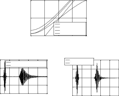
Due to the strongly dispersive nature of hollow waveguides, individual frequency components travel at different phase velocities. Hence the profile of short pulses in the time domain with associated rich frequency contents undergoes distortion as they propagate along these waveguides. This typically results in broadening the duration of the pulse and can be a limiting factor in cases where short pulses are required, in e.g. radar applications for high resolution sensing. With the introduction of periodic loading in the waveguide it is possible to produce an equivalent transmission line with significantly reduced dispersion within a frequency range. The ‘linearization’ of the dispersion relation suggests reduced distortion of signals with broad spectral characteristics. Here, by means of an example involving a 400ps gaussian pulse modulating a carrier at 9GHz and propagating along 80cm, we demonstrate how a carefully designed EBG waveguide of the type discussed in [2] can reduce these unwanted effects.
The dispersion relation for the TE10 mode of an X-band is plotted in Fig. 5, where for comparison the light line is also shown. The nonlinearity of the dispersion is evident, especially towards the cutoff. The dispersion of an E- plane EBG waveguide of the type discussed in [2] with (in mm) D= 4.0, s= 3.0, t= 0.1 and Lr= 2.0 is also shown in Fig. 5. Due to the introduction of the ridge waveguide sections, the cutoff frequency drops to 5.5 GHz in this case. Nevertheless, due to the slow wave effect the dispersion experienced is significantly more linear in the 7-11 GHz bandwidth compared to the hollow waveguide case. Fig. 6 shows a time domain representation of the pulse at the input and output of 80cm long rectangular hollow waveguides and the EBG waveguide with dispersion relations shown in Fig. 5.
|
15 |
|
|
|
|
(GHz) |
|
|
|
|
|
frequency |
10 |
|
|
|
|
|
|
free space |
|
||
|
|
TE10 (X band) |
|
||
|
|
|
|
||
|
|
|
TE10 (fc=5.5GHz) |
||
|
50 |
|
EBG |
|
|
|
0.1 |
0.2 |
0.3 |
0.4 |
|
|
|
|
beta (rad/mm) |
|
|
Fig 5: Dispersion relation of a rectangular X-band and a X-band EBG waveguide in the same housing with D=4.0, t=0.1, s=3.0, Lr=2.0.
amplitude (normalised)
1 |
input pulse |
|
|
|
|
input1 pulse |
|
|
|
|
||
|
|
|
|
|
output pulse (EBG) |
|
|
|
||||
|
output pulse (TE10 - X band) |
|
|
|
|
|||||||
|
(normalised) |
0 |
|
|
|
|
|
|||||
0.5 |
|
|
|
|
|
|
|
|
|
|
||
|
|
|
|
|
|
0.5 |
|
|
|
|
|
|
|
|
|
|
|
|
|
|
|
|
|
|
|
0 |
|
|
|
|
|
amplitude |
|
|
|
|
|
|
-0.5 |
|
|
|
|
|
-0.5 |
|
|
|
|
|
|
|
|
|
|
|
|
|
|
|
|
|
||
|
|
|
|
|
|
|
|
|
|
|
|
|
-10 |
2000 |
4000 |
6000 |
8000 |
10000 |
|
-10 |
|
|
|
|
|
|
|
time (psec) |
|
|
|
2000 |
4000 |
6000 |
8000 |
10000 |
||
|
|
|
|
|
|
|
|
|
time (psec) |
|
|
|
(a) |
(b) |
Fig 6: Time domain plot of the input pulse (dashed line) and the output pulse (solid line) through an h=80 cm long transmission line supporting (a) X-band TE10 mode (b) the EBG waveguide.
An alternative method to achieve matching of the periodic structure is by gradually increasing the gap between the two ridges towards the rectangular waveguide input and output ports. A tapered matching section was designed, for a waveguide consisting of 8 unit cells matched at both input and output. To validate the performance of the tapered matching, Fig. 7 shows the reflection and transmission coefficient from the finite structure shown in the inset consisting. As shown, a reflection coefficient at the level of 20dB is achieved. Experimental testing on this prototype is currently ongoing and will be reported shortly.

Frequency (GHz)
|
6.5 |
8 |
9.5 |
11 |
12.5 |
14 |
|
0 |
|
|
|
|
|
(dB) |
-20 |
|
|
|
|
|
parameters |
-40 |
|
s11 |
(HFSS) |
|
|
S- |
|
|
s12 |
(HFSS) |
|
|
|
|
|
|
|
||
|
|
|
s11 |
(MM) |
|
|
|
|
|
s12 |
(MM) |
|
|
|
-60 |
|
|
|
|
|
Fig 7: Schematic layout of a tapered periodic waveguide section and simulated reflection and transmission response.
C. BANDPASS FILTERS
The slow wave region of the periodically loaded waveguide can be employed to produce miniaturised resonators, In [3] was reported a 50% miniaturisation for a 2nd order filter, together with an improvement in the stopband performance. To demonstrate the versatility, here an example, a fifth-order X-band bandpass filter has been designed. In this example, the passband is between 8.5GHz and 9.0GHz and a Chebyshev response with ripple 0.5dB has been selected. The exact dimensions of the designed prototype are given in Table 1.
Table 1: Dimensions (in mm) of the conventional and periodic E-plane waveguide filters.
|
Ls1= Ls6 |
Ls2= Ls5 |
Ls3= Ls4 |
Lr1= Lr5 |
Lr2= r4 |
Lr3 |
Total |
|
|
|
|
|
13.2 |
13.2 |
13.2 |
|
|
Periodic |
2.00 |
6.65 |
7.55 |
s= 3.15 |
s= 2.94 |
s= 2.94 |
98.40 |
|
Lw= 1.2 |
Lw= 1.2 |
Lw= 1.2 |
||||||
|
|
|
|
|
||||
|
|
|
|
Lr= 1.2 |
Lr= 1.2 |
Lr= 1.2 |
|
|
Conventional |
1.25 |
4.96 |
5.85 |
19.86 |
20.38 |
20.38 |
129.98 |
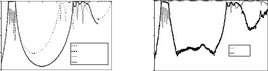
The length of each EBG resonator is 13.2mm and of the total filter is 98.4mm. The simulated response as obtained from a combination of the generalised transverse resonance technique and the mode-matching method [4] is shown in Fig. 8. For comparison of the performance, the response of a conventional E-plane filter is also superimposed. The dimensions of latter are also shown on Table 1. The length of the conventional resonator is about 20.0mm and the one of the total filter 130mm. This validates the estimated length reduction as obtained from the equivalent permittivity, although some adjustments are required to optimize the passband response. This will be the topic of a following publication. The superior stopband performance of the periodic filter is in good agreement with the nature of the ridge waveguide filters [4].
Frequency (GHz)
|
8 |
9 |
10 |
11 |
12 |
13 |
14 |
15 |
16 |
|
|
0 |
|
|
|
|
|
|
|
|
|
(dB) |
-20 |
|
|
|
|
|
|
|
|
|
|
|
|
|
|
|
|
|
|
|
|
eters |
-40 |
|
|
|
|
|
|
|
|
|
param |
|
|
|
|
|
|
|
|
|
|
|
|
|
|
|
|
S12 |
(conventional) |
|
||
S- |
-60 |
|
|
|
|
|
S12 |
(conventional) |
|
|
|
|
|
|
|
|
|
||||
|
|
|
|
|
|
|
|
|
|
|
|
|
|
|
|
|
|
S11 |
(periodic) |
|
|
|
|
|
|
|
|
|
S12 |
(periodic) |
|
|
|
-80 |
|
|
|
|
|
|
|
|
|
Frequency (GHz)
|
8 |
9 |
10 |
11 |
12 |
13 |
14 |
15 |
16 |
|
0 |
|
|
|
|
|
|
|
|
|
-20 |
|
|
|
|
|
|
|
|
(dB) |
|
|
|
|
|
|
|
|
|
eters |
-40 |
|
|
|
|
|
|
|
|
S-param |
|
|
|
|
|
|
|
|
|
|
|
|
|
|
|
S11 (dB) |
|
|
|
|
-60 |
|
|
|
|
|
S12 (dB) |
|
|
|
-80 |
|
|
|
|
|
|
|
|
Fig. 8, Solid/dashed lines: simulated response of the periodic/ |
Fig. 9, Measured response of the periodic filter prototype. |
conventional E-plane filter with dimensions shown in Table 1. |
|
In order to validate the design, the filter has been fabricated and measured. Brass has been milled for the waveguide housing and the E-plane circuit was routed on a copper foil of thickness 0.1mm. The measured reflection and transmission coefficients are shown in Fig. 9. Very good agreement between the simulated and the experimental results is observed. The noise level of the measurement equipment was about -60dB. The insertion loss in the passband at a frequency point of low reflection is 1dB, with about 0.5dB the loss of the empty waveguide. That suggests that near the midband frequency the ohmic losses are of the order to 0.5dB, which can be further reduced with a selection of higher conductivity metals.
E-PLANE FILTERS WITH TRANSMISSION ZEROS
Despite of their favourable characteristics, E-plane filters suffer from bulky size and stopband performance that may often be too low for many applications, such as multiplexers. Furthermore, many multi-channel or diplexer applications require filters with sharp cutoff, in order to accommodate for closely spaced frequency channels and avoid cross-talk. The requirement of steep attenuation slopes is very conveniently addressed with transmission zeros positioned close to the cutoff of the filter, rather than increasing the order of the filter, which in turn would increase the size and the losses. Similarly, the out-of-band rejection performance can be locally improved by selectively positioning transmission zeros. To address this requirement, Ofly et. Al. recently proposed a folded configuration that allows cross-coupling between the resonators in order to produce a pseudo-elliptic response [5], at the cost of fabrication simplicity.
In [3] a 3rd order E-plane filter compatible with the thin all-metal insert split-block housing E-plane topology was demonstrated to produce sharp higher frequency roll-off implementing a transmission zero. The topology in [6] involved both series and parallel coupled resonators and it was argued that the transmission zero emerges due to cross coupling between the three resonators. Economizing in size and complexity, the possibility to selectively position transmission zeros in a bandpass filter using a pair of parallel coupled resonators compatible with the lowcost and mass-producible characteristics of thin all-metal insert-block E-plane topology has been recently successfully reported.

b |
a |
|
|
|
|
|
Lr1 |
Ls10 |
su |
|
|
|
s1 |
|
|
b |
s |
|
|
|
s2sd |
|
|
|
Ls23 |
Lr2 |
Ls12 |
|
Fig. 10 Schematic layout of the open ended oven concept
In this case, the resonators are etched as half wavelength slots in the all-metal E-plane insert and are arranged symmetrically in the waveguide as shown in the schematic of Fig. 10. This coupling arrangement produces a transmission zero at finite frequencies. Moreover, it allows two free variables in controlling the coupling coefficient in the passband, namely the overlap length (horizontal), Ls12, and the vertical separation. Different combinations of the two parameters allow for selective positioning of the transmission zero. Basically, by increasing the overlap the transmission zero drops down. It is feasible and easy to produce both low and upper TZ prototypes by means of accurately setting the dimensions and locating the resonators.
Fig 11, Second order filters with passband centred at 8.9GHz and transmission zeros located in the upper stopband. Dimensions (in mm) (a) Lr1= Lr2= 16, s1= s2= 2.1, s= 1.7
Fig 12, Second order filters with passband centred approximately at 8.9GHz and transmission zeros located in the lower atopband. Varying dimensions (see main document).
In order to verify this idea, two second order filters with approximately the same passband response (tunned at 8.9 GHz and 0.35 GHz passband width) has been designed, see Fig 13a and 13b; further simulations with Ansoft HFSS commercial software, fabrication and measurement has been successfully carried out. Good agreement between simulations and measurements has been shown. See Fig 13c, 13d.

Frequency (GHz)
|
8 |
9 |
10 |
11 |
12 |
13 |
14 |
(d B ) |
0 |
|
|
|
|
|
|
|
|
|
|
|
|
|
|
nt |
-10 |
|
|
|
|
|
|
c o e ffic ie |
|
|
|
|
|
|
|
-20 |
|
|
|
|
|
|
|
sio n |
|
|
|
|
|
|
|
|
|
|
|
Upper Tz (Sim) |
|
||
m is |
-30 |
|
|
|
|
|
|
ns |
|
|
|
|
Lower TZ (Sim) |
|
|
T ra |
|
|
|
|
|
||
|
|
|
|
|
|
|
|
|
-40 |
|
|
|
|
|
|
|
|
|
|
(a) |
|
|
|
Frequency (GHz)
|
8.3 |
8.5 |
8.7 |
8.9 |
9.1 |
9.3 |
9.5 |
|
0 |
|
|
|
|
|
|
B ) |
-10 |
|
|
|
|
|
|
( d |
|
|
|
|
|
|
|
d e |
|
|
|
|
|
|
|
g n itu |
-20 |
|
|
|
|
|
|
|
|
|
|
|
S12 (Sim) |
|
|
M a |
|
|
|
|
|
|
|
-30 |
|
|
|
|
S12 (Exp) |
|
|
|
|
|
|
|
S11 (Sim) |
|
|
|
|
|
|
|
|
|
|
|
|
|
|
|
|
S11 (Exp) |
|
|
-40 |
|
|
|
|
|
|
|
|
|
|
(c) |
|
|
|
(b)
Frequency (GHz)
|
8.3 |
8.5 |
8.7 |
8.9 |
9.1 |
9.3 |
9.5 |
9.7 |
|
0 |
|
|
|
|
|
|
|
) |
-10 |
|
|
|
|
|
|
|
( d B |
|
|
|
|
|
|
|
|
|
|
|
|
|
|
|
|
|
d e |
|
|
|
|
|
|
|
|
a g n itu |
-20 |
|
|
|
|
|
|
|
|
S12 (Sim) |
|
|
|
|
|
|
|
M |
|
|
|
|
|
|
|
|
-30 |
S12 (Exp) |
|
|
|
|
|
|
|
|
|
|
|
|
|
|
||
|
|
S11 (Sim) |
|
|
|
|
|
|
|
|
S11 (Exp) |
|
|
|
|
|
|
|
-40 |
|
|
|
|
|
|
|
|
|
|
|
|
(d) |
|
|
|
Fig13. Simulated transmission response (a) of the two photographed (b) designed prototypes. (Lower TZ prototype on right hand side). Comparison between the simulated and measured transmission and reflection response for the low (c) and upper (d) TZ
prototypes. Dimensions in mm: Lower TZ prototype are Lr1= Lr2= 16, s1= s2= 2.1, s= 1.5 Ls12= 11.4 Upper TZ prototype are Lr1= Lr2= 16, s1= s2= 2.1, s= 1.7, Ls12= 8.4
CONCLUSION
E-plane technology offers possibilities to realise filters and other waveguide components with superior performance maintaining low cost, mass producibility and good fabrication tolerances. In this contribution we have demonstrated lowpass periodic E-plane waveguides which have successfully employed as lowpass filters as well as to miniaturise the resonators of Bandpass filters. Moreover, periodic E-plane inserts can be used for compensation of the dispersion during waveguide propagation, which can be particularly useful for transmission of pulses with short time domain profile along considerable lengths. In addition we have demonstrated that all metal single E-plane insert technology allows for the realisation of Bandpass filters with selectively located transmission zeros. Numerical and experimental results have been presented throughout to validate the performance.
REFERENCES
[1]G. Goussetis, A.P. Feresidis and P. Kosmas, “Efficient Analysis, Design and Filter Applications of EBG Waveguide with Periodic Resonant Loads,” IEEE Transactions on Microwave Theory and Techniques, Vol. 54, No. 11, pp. 3885-3892, November 2006
[2]G. Goussetis, N. Uzunoglou, J.-L. Gomez-Tornero, B. Gimeno, V.E. Boria, “An E-plane EBG Waveguide for Dispersion Compensated Transmission of Short Pulses”, IEEE Antenna and Propagation Symposium, Honolulu, Hawaii, 9-15 June, 2007
[3]G. Goussetis and D. Budimir, “Novel Periodically Loaded E-plane Filters”, IEEE Microwave and Wireless Components Letters, pp 193-195, Vol.13, No. 6, June 2003
[4]G. Goussetis and D.Budimir “Bandpass filters with improved stopband performance”, Microwave Conference, 2000 Asia-Pacific, vol, no., pp.529-532, 2000
[5]E. Ofli, R. Vahldieck, S. Amari, “Novel E-plane filters and diplexers with elliptic response for millimeter-wave applications,” IEEE Transactions Microwave Theory and Techniques, Vol. 53, No. 3, 1, pp. 843-851, March 2005
[6]G. Goussetis, A.P. Feresidis, D. Budimir, and J.C. Vardaxoglou, “Compact Ridge Waveguide Filter with Parallel and Series Coupled Resonators,” Microwave and Optical Technology Letters, Vol. 45, No. 1, pp. 22-23, April 2005
[7]Postoyalko, V.; Budimir, D.S., "Design of waveguide E-plane filters with all-metal inserts by equal ripple optimization", Microwave Theory and Techniques, IEEE Transactions on , vol.42, no.2, pp.217-222, Feb 1994
[8]Jia-Sheng Hong, “Design of E-plane filters made easy”, IEE Proceedings Microwaves, Antennas and Propagation (H), pp. 215 –218, Vol. 136, Issue 3, June 1989
[9]F. Arndt. “Status of the rigorous design of millimeter wave low insertion loss fin-line and metallic E-Plane filters”, J. Instr Eletron, Telecom. Eng. Vol. 34, pp 107-119, 1988
[10]Bornemann, J.; Arndt, F., "Metallic E-plane filter with cavities of different cutoff frequency," Electronics Letters , vol.22, no.10, pp.524-525, May 8 1986
[11]Vahldieck R., Bornemann J., Arndt F., Grauerholz D., “W-Band Low-Insertion-Loss E-Plane Filter”, IEEE Transactions on Microwave Theory and Techniques, pp. 133 -135, Vol. 32, Issue 1, Jan 1984
[12]Yi-Chi Shih, "Design of Waveguide E-Plane Filters with All-Metal Inserts," Microwave Theory and Techniques, IEEE Transactions on , vol.32, no.7, pp. 695-704, Jul 1984
[13]Shih, Y.C.; Itoh, T.; Bui, L.Q., "Computer-Aided Design of Millimeter-Wave E-Plane Filters," Microwave Symposium Digest, MTT-S International , vol.82, no.1, pp. 471-473, Jun 1982