

диафрагмированные волноводные фильтры / 8f4fc74e-8950-4981-acd6-e40b3f15c2cb
.pdfSee discussions, stats, and author profiles for this publication at: https://www.researchgate.net/publication/315379591
A Hybrid Stepped Impedance – Ring Resonator Loaded Waveguide Bandpass Filter with Dual Pole and Four Transmission Zeros
Conference Paper · March 2017
CITATIONS |
READS |
0 |
127 |
2 authors, including:
Amit Bage
National Institute of Technology, Hamirpur
40 PUBLICATIONS 141 CITATIONS SEE PROFILE
All content following this page was uploaded by Amit Bage on 19 March 2017.
The user has requested enhancement of the downloaded file.
Template for submitting papers to URSI-RCRS 2017 |
1 |
A Hybrid Stepped Impedance – Ring Resonator Loaded Waveguide Bandpass Filter with Dual Pole and Four Transmission Zeros
A.Bage, and S. Das
A.Bage is with the Indian Institute of Technology (Indian School of Mines), Dhanbad, Jharkhand 826004 India (corresponding author to provide phone: +91-326-2235496; fax: +91-326-2296622; e-mail: bageism@gmail.com).
S. Das is with the Electronics Engineering Department, University Indian Institute of Technology (Indian School of Mines), Dhanbad, Jharkhand 826004 India, (e-mail: sushrut_das@yahoo.com).
ABSTRACT
This paper presents a, hybrid stepped impedance–ring resonator loaded waveguide bandpass filter with dual pole and four transmission zeros. Two Roger RT/Duroid 5880 substrates, printed with ring resonator and stepped impedance resonator, have been placed on the transverse plane of a WR–90 waveguide at a distance 9.49 mm to achieve above filter characteristics. The structure has been simulated in HFSS (version 14). The simulated result shows 0.81 GHz 3–dB bandwidth at the center frequency 9.92GHz with transmission zeros location are 7.25/ 10.73/ 9.27 and 11.8 GHz.
Keywords:
Bandpass Filter, Transmission Zeros, Stepped Impedance Resonator, Waveguide.
1. INTRODUCTION
Waveguide filters play an important role in the microwave and mm wave systems, due to their numerous advantages like low insertion loss, high return loss, high power handling capability, and high quality factor. The disadvantages are weight, complexity in fabrication and high fabrication cost. To overcome these problems, direct coupled H–plane waveguide filters were proposed [1–4]. However they have poor out of band performance.
In present day communication systems, electromagnetic interference is a big concern. Unwanted radiations from nearby / far filed sources often get coupled to the system through the transmitting / receiving antenna and cause system malfunction. Therefore filters with sharp skirt selectivity and good stop band performances are often recommended for use. One of the ways to achieve sharp skirt and good stop band performance is to insert transmission zeros (TZs) in the stop band.
There are different techniques to insert TZs in the filter response. Perhaps the most common of them is to implement cross coupling between the resonators, in which positive and negative couplings are needed to generate TZs at finite frequencies [5]. Some other alternatives are use of higher order waveguide cavity modes [6], use of frequency selective surfaces in the transverse plane of the waveguide [7–8], and integration of planar structure into the evanescent mode waveguide [9]. In [10–11], E- plane waveguide based bandpass filters have been designed to achieve two TZs at both sides of the passband.
The objective of this paper is to propose a compact, dual pole waveguide bandpass filter with multiple stopband TZs. Hybrid rectangular ring resonator (RRR) – stepped impedance resonator (SIR) structure, printed on Roger RT/Duroid 5880 substrate, has been used for this purpose. Initially a single
RRR-SIR resonator has been designed to resonate at 9.92 GHz, with two TZs. At the final stage, two RRR-SIR resonators, with different dimensions, are placed at distance of 9.49 mm to achieve the dual pole bandpass characteristics with four TZs.
2.FILTER DESIGN THEORY
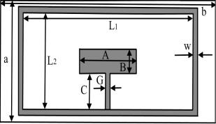
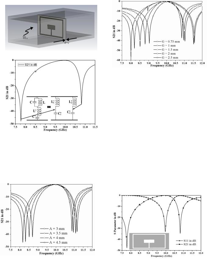
The proposed RRR-SIR structure is shown in Fig. 1 (a). To study its characteristics, the resonator has been placed on the transverse plane of a standard WR–90 rectangular waveguide, as shown in Fig. 1(b). The resonator has been designed on a Roger RT/Duroid 5880 substrate with relative permittivity 2.22, dielectric loss tangent 0.0009, substrate height 0.508 mm and copper thickness 0.035mm. The structure has been simulated in HFSS (Version 14) and the simulated |S21| response is shown in Fig. 1 (c) along with its equivalent circuit. In the equivalent circuit, L1' and C1' are responsible for lower attenuation pole whereas L2' and C2' are responsible for upper attenuation pole.
Fig. 1. (a) cross sectional view of the resonator.
Template for submitting papers to URSI-RCRS 2017 |
2 |
Fig. 1. (b) Single resonator loaded into the rectangular waveguide.
Fig. 1. (c) Simulated frequency response of |S21|.
To demonstrate the tunability of the TZs, the widths of the SIR have been varied individually and the corresponding responses are presented in Fig. 2. The results reveal that as “A” increases, the TZs shifts towards the lower frequencies where as “G” increases, the TZs shifts towards the higher frequencies. Therefore by adjusting “A” and “G” TZs can be located at the desired frequencies.
(a)
(b)
Fig. 2.Frequency response of |S21|with variations in (a) A [G=0.5] and (b) G [A=6]. Other parameters: B= 2, C= 3, w= 1,L1 = 18, L2 = 8.
3. FILTER DESIGN, RESULTS AND DISCUSSION
Results in section II reveal that the proposed unit cell provides a band pass response with two TZs, that can positioned at the desired locations by varying the widths of the SIR. This indicates that if two resonators are used, instead of one, and if the dimensions of these two resonators are kept different then there is a possibility of more stop band TZs. For target specific TZs, the dimensions of the SIRs can be chosen such that they result in TZs at the target frequencies.
To investigate the concept, two resonators of different dimensions have been considered and simulated individually. The dimensions of the resonators are optimized in such a way that the TZs are obtained at 7.75 GHz and 10.73 GHz for resonator 1 and 9.27 GHz and 12 GHz for resonator 2. During optimization care also has been taken so that both the structures resonate at the same frequency (9.92 GHz). The optimized dimensions are A = 6 mm, B = 2 mm, C = 3 mm, G = 0.5 mm, w = 0.5 mm, L1 = 18 mm, and L2 = 8 mm, for resonator 1 and A = 2.41 mm, B = 2 mm, C = 2 mm, G = 0.7 mm, w = 1 mm, L1 = 18 m, and L2 = 8 mm for resonator 2. The simulated frequency responses are shown in Fig. 3.
(a)

Template for submitting papers to URSI-RCRS 2017 |
3 |
(b) |
|
Fig. 3. Simulated frequency responses of unit cells with (a) resonator 1 and |
|
(b) resonator 2. |
Fig. 5 Simulated Frequency response of proposed filter. |
Next, the above resonators have been placed on the transverse plane of the waveguide to form the second order (i.e., dual pole) band pass filter, as shown in Fig. 4. The spacing between the resonators (9.49 mm) has been optimized for an acceptable result. Total length of the filter therefore becomes 10.5 mm, excluding the thickness of copper cladding (9.49+0.508+0.508 mm).
Fig. 4. Integration of first and second resonator into rectangular waveguide.
Simulated frequency response of the proposed filter is shown in Fig. 5, which reveals a band pass response with center frequency at 9.92 GHz and TZs at 7.25 GHz and 10.73 GHz, 9.27 GHz and 11.8 GHz. The simulated result also reveals that the filter has 0.81 GHz 3dB bandwidth at 9.92 GHz (fractional bandwidth 8.12%). A table has been tabulated in Table 1, which compares the characteristics of proposed filter with few other reported filters [1, 3, 7-8].
Table 1: comparison of the filter characteristcs
Reference |
Centre |
Insertion |
Return |
No. of |
Length |
|
Frequency |
Loss (dB) |
Loss |
TZs |
(mm) |
|
(GHz) |
|
(dB) |
|
|
[1] |
10.03 |
0.45 |
15.21 |
- |
20.33 |
[3] |
11.95 |
0.5 |
10 |
- |
15.02 |
[7] |
10 |
1.7 |
17 |
6 |
20.42 |
[8] |
10 |
0.58 |
20 |
6 |
19.875 |
Proposed |
9.92 |
0.15 |
18.5 |
4 |
10.5 |
|
4. CONCLUSION
This paper presents a new and efficient way to control and insert multiple TZs at the stop band of a waveguide band pass filter. The center frequency of the filter can be chosen by optimizing the rectangular ring resonator dimensions whereas the TZs can be located at the target specific frequencies by optimizing the SIR dimensions.
REFERENCES
1.A. Bage and S. Das, “A compact, wideband waveguide bandpass filter using complementary loaded split ring resonators,” Prog. In Electromag. Res. C, vol. 64, pp. 51–
59, 2016.
2.A. Bage and S. Das, “Wideband waveguide band-pass filter based on Broad Side Complementary Split Ring
Resonator,” Int. Conf. On Microw. and Photon. (ICMAP), pp. 1–2, 2015.
3.H. Bahrami, M. Hakkak, and Pirhadi, Analysis and design of highly compact bandpass waveguide filter utilizing complementary split ring resonators (CSRR), Prog. Electromagn. Res., vol. 80, pp. 107–122, 2008.
4.A. Bage, and S. Das, Studies of some non conventional split ring and complementary split ring resonators for waveguide band stop & band pass filter application, Int. conf. microw. and photonics (ICMAP), pp. 1 – 5, 2013.
5.J.-S. Hong and M. J. Lancaster, “Couplings of microstrip square open-loop resonators for cross-coupled planar microwave filters,” IEEE Trans. Microw. Theory Tech., vol. MTT–24, no. 12, pp. 2099–2109, Dec. 1976.
6.T. Shen, H.-T. Hsu, K. A. Zaki, A. E. Atia, and T. G. Dolan, “Full-wave design of canonical waveguide filters by optimization,” IEEE Trans. Microw. Theory Tech., vol. 51, no. 2, pp. 504–510, Feb. 2003.
7.M. Tsuji, H. Deguchi, and M. Ohira, “A new frequency selective window for constructing waveguide bandpass filters with multiple attenuation poles,” Prog. In
Electromag. Res. C, vol. 20, pp. 139–153, 2011.
8.M. Ohira, H. Deguchi, M. Tsuji, and H. Shigesawa,
“Novel Waveguide Filters With Multiple Attenuation
Template for submitting papers to |
URSI-RCRS 2017 |
4 |
Poles Using Dual-Behavior |
Resonance of Frequency- |
High Selectivity and Compact Size,” Int. Journal of RF |
Selective Surfaces,” IEEE Trans. Microw. Theory Tech., |
Microw. Comput. Aided Engg., vol. 17, pp. 451–456, |
|
vol. 53, No. 11, pp. 3320–3326, November 2005. |
2007. |
|
9.M. Ohira, T. Matsumoto, Z. Ma, H. Deguchi, and M. 11. J. Ye Jin, X. Q. Lin, Y. Jiang, and Q. Xue, “A Novel
Tsuji, “A |
new type of compact evanescent mode |
Compact -Plane Waveguide Filter with Multiple |
waveguide |
bandpass filter using planar dual-behavior |
Transmission Zeroes,” IEEE Trans. Microw. Theory |
resonators,” Proc. Asia-Pacific Microw. Conf., pp. 1023– |
Techn., vol. 63, no. 10, pp. 3374–3380, Oct. 2015. |
|
1026, 2011. |
|
|
10.J. Y. Jin, X. Q. Lin, Y. Jiang, L. Wang and Y. Fan, “A
Novel E-Plane Substrate Inserted Bandpass Filter with
View publication stats