

диафрагмированные волноводные фильтры / b7551a94-b869-49ac-b2f0-6b25dcccbf21
.pdfCOMPACT RIDGE WAVEGUIDE FILTER WITH PARALLEL AND SERIESCOUPLED RESONATORS
G. Goussetis,1 A. P. Feresidis,1 D. Budimir,2 and
J. C. Vardaxoglou1
1 Wireless Communications Research Group
Department of Electronic and Electrical Engineering
Loughborough University
Leicestershire, LE11 3TU, UK
2 Wireless Communications Research Group
Department of Electronic Systems
University of Westminster
115 New Cavendish Street
London, W1M 8JS, UK
Received 21 September 2004
ABSTRACT: A novel 3rd-order compact E-plane ridge waveguide filter is presented. Miniaturization is achieved upon introducing a configuration of parallel-coupled E-plane ridge waveguide resonators. Furthermore, the proposed filter allows for transmission zeros at finite frequencies. Fabrication simplicity and mass producibility of standard E-plane filters is maintained. The numerical and experimental results are presented to validate the proposed configuration. A miniaturisation factor of 2 and very sharp upper cutoff are achieved. © 2005 Wiley Periodicals, Inc. Microwave Opt Technol Lett 45: 22–23, 2005; Published online in Wiley InterScience (www.interscience.wiley.com). DOI 10.1002/ mop.20711
Key words: E-plane filters; transmission zeros; parallel coupling; compact filters
1. INTRODUCTION
All-metal inserts mounted in the E-plane of a split block waveguide housing is a well-established technique for realising low-cost and mass-producible microwave configurations, such as bandpass filters [1– 6]. However, despite their favourable characteristics, E-plane filters suffer from bulky size [2, 3]. Furthermore, many multichannel or diplexer applications require filters with sharp cutoff in order to accommodate for closely spaced frequency channels and avoid cross-talk. The requirement of steep attenuation slopes is very conveniently addressed by positioning transmission zeros close to the cutoff of the filter, rather than by increasing the order of the filter, which in turn would increase the size and the losses.
In this paper, we propose a novel configuration that significantly reduces the physical dimension of bandpass E-plane filters. The improvement is achieved upon introducing parallel coupling between the resonators of ridge waveguide filters. This results in a significant reduction of the total size of the filter. Furthermore, the topology allows for cross-coupling between the resonators, thus introducing transmission zeros at finite frequencies. The proposed filter is compatible with the low-cost and mass-producible fabrication process of conventional E-plane filters [1, 2] and can be directly integrated with low-pass (EBG) waveguide components for suppression of spurious harmonic resonances [5]. The performance of the proposed topology is demonstrated using a 3rd-order
Figure 1 Layout of the proposed topology for a 3rd-order filter
filter design. The simulated end experimental results are presented. A size reduction of 2:1 and sharp upper cutoff are achieved.
2. DESIGN
The full-wave transverse resonance technique has been implemented to solve the problem of electric-field distribution in a ridge waveguide with thin ridges and narrow gaps. This technique, in combination with the full-wave mode-matching method [5], has been employed for the design of standard half-wavelength resonators at the operating frequency [6]. The required couplings between resonators for specific filter performance have been determined according to well-established techniques [5].
In the proposed configuration, successive resonators are coupled in parallel. Resonators 1 (Lr1) and 2 (Lr2) are coupled along section Ls12, while resonators 2 (Lr2) and 3 (Lr3) are coupled along section Ls23. Furthermore, the first (Lr1) and third (Lr3) resonators are cross-coupled in series through the septum between them Ls13. This cross-coupling accounts for a finite transmission zero. Cascading triplets, as shown in Figure 1, would allow realisation of higher-order filters. Optimisation of the total structure has been carried out at the last stage of the design in order to ensure the specified return loss in the passband and the positioning of the transmission zero at the upper cutoff for sharp rolloff. A commercial TLM-based software package [7] has been employed for this final stage of the design.
3. NUMERICAL AND EXPERIMENTAL RESULTS
A 3rd-order filter was designed (Fig. 1), with the centre frequency at 9.0 GHz and 0.8-GHz bandwidth with 0.5-dB ripple. The filter has also been fabricated and measured, and the dimensions are given in Table 1. The simulated and measured results are shown in Figure 2. A picture of the fabricated prototype is shown in Figure 3. Good agreement between the simulation and the measurement
TABLE 1 Dimensions of the Designed Prototype
L L L
s10
s23
s13
L
L
s34
s12
0.50 |
Lr1 Lr3 |
15.00 |
|
s |
2.40 |
a |
22.86 |
5.50 |
Lr2 |
15.00 |
s1 |
s2 |
2.00 |
b |
10.16 |
4.00 |
|
— |
su |
sd |
1.88 |
t |
0.10 |
22 MICROWAVE AND OPTICAL TECHNOLOGY LETTERS / Vol. 45, No. 1, April 5 2005
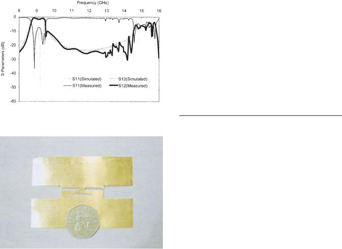
Figure 2 Simulated and measured results for the designed and fabricated prototype of a 3rd-order filter (dimensions as in Table 1)
Figure 3 Photograph of the fabricated prototype. [Color figure can be viewed in the online issue, which is available at www.interscience.wiley. com.]
has been achieved. Slight discrepancies are due to mechanical tolerances of the fabricate prototype, which was built using mechanical etching [6]. The total dimension of the filter is 35.0 mm, corresponding to 50% of the size of a conventional E-plane filter with same specifications. The upper 3-dB cutoff frequency is 9.49 GHz and more than 10-dB attenuation has been achieved at 9.5 GHz due to the finite transmission zero.
4. CONCLUSION
A novel parallel-coupled ridge waveguide-filter topology has been proposed. Miniaturisation by a factor of 2 was achieved upon introducing the parallel coupling of narrow-gap resonators. This topology also allows for cross couplings between resonators and hence the emergence of transmission zeros at finite frequencies. The finite transmission zero has provided a sharp upper cutoff. The simulated and experimental results have been presented. Good agreement between the measurement and the simulation has been observed.
REFERENCES
1.D. Budimir and G. Goussetis, Design of asymmetrical RF and microwave bandpass filters by computer optimization, IEEE Trans Microwave Theory Tech 51 (2003), 1174 –1178.
2.G. Goussetis and D. Budimir, Novel periodically loaded E-plane filters, IEEE Microwave Wireless Compon Lett 13 (2003), 193–195.
3.A. Kirilenko, L. Rud, V. Tkachenko, and D. Kulik, Evanescent-mode ridged waveguide bandpass filters with improved performance, IEEE Trans Microwave Theory Tech 50 (2002), 1324 –1327.
4.D. Budimir, Generalized filter design by computer optimization, Artech House, Boston, 1998.
5.G. Goussetis and D. Budimir, Compact ridged waveguide filters with improved stopband performance, IEEE MTT-S Int Microwave Symp Dig 2 (2003), 953–956.
6.G. Goussetis, D. Budimir, and J. Helszajn, Upper and lower bounds of 180° unit element of a ridge waveguide: Calculations and measure-
ments, Microwave Opt Technol Lett 31 (2001), 260 –261.
7.Microstripes v. 6.0, Flomerics Ltd., Electromagnetics division.
8.Protomat C60, LPKF Laser & Electronics AG.
© 2005 Wiley Periodicals, Inc.
AN APPROXIMATE PARALLEL-PLATE WAVEGUIDE MODEL OF A LOSSY MULTILAYERED MICROSTRIP LINE
G. A. Kouzaev,1 M. J. Deen,1 N. K. Nikolova,1 and A. Rahal2
1 Department of Electrical and Electronic Engineering McMaster University
1280 Main St. W.
Hamilton ON, L8S 4K1 Canada
2 Nanowave Technologies Inc. Etobicoke ON, M8W 4W3 Canada
Received 16 September 2004
ABSTRACT: An analytical model of a lossy microstrip line that is valid at frequencies up to 40 GHz is proposed. The line consists of a two-layer dielectric substrate and lossy strip. The model is based on the theory of the TM mode of a lossy parallel-plate waveguide filled with a medium of effective permittivity. © 2005 Wiley Periodicals, Inc. Microwave Opt Technol Lett 45: 23–26, 2005; Published online in Wiley InterScience (www.interscience.wiley.com). DOI 10.1002/mop. 20712
Key words: multilayered microstrip lines; conductor loss
1. INTRODUCTION
Multilayered microstrip lines are now used in many microwave hybrid and monolithic integrated circuits (IC) [1–5]. They are composed of multilayer substrates and lossy conductors (Fig. 1). These lines have been studied mainly via numerical methods [5, 6]. Very few papers have reported measured loss in such transmission lines [7]. An analytical quasistatic model was proposed [8] in which the effective dielectric constant and the characteristic impedance are obtained by conformal mapping. In [9], the loss is computed by the use of the incremental inductance rule that is applicable only to thick (compared to skin depth) conductors. Monolithic multilayered transmission lines, however, are produced by thin-film technology, and they are used in applications where the frequency band is from zero to several tens of Gigahertz. At low frequencies, the electromagnetic field penetrates the conductors, and the models based on the skin effect and the incremental inductance rule do not provide adequate accuracy. At high frequencies, the models should also take into account the modal dispersion caused by the multilayered cross section. In [10], such a wide-frequency model (0 –100 GHz) of a monolayer microstrip transmission line has been developed using a parallel-plate waveguide approach. The fundamental mode is approximated by the TMz-mode, with z the direction of propagation of a lossy parallel-plate waveguide filled with a medium of frequency-depen-
MICROWAVE AND OPTICAL TECHNOLOGY LETTERS / Vol. 45, No. 1, April 5 2005 |
23 |