

диафрагмированные волноводные фильтры / 1fbce6e2-573c-4ff2-8964-6a49935b4497
.pdfFigure 4 The gain of the AEP of E-plane notch phased array and the beam steering gain. [Color figure can be viewed in the online issue, which is available at www.interscience.wiley.com]
volume of 45°. And the measured ARC also shows a good agreement with the simulation result.
Using the proposed method, the gain of E-plane notch phased array antenna is calculated. In Figure 4, the gain of the AEP in proposed method and the measured AEP are shown respectively and also compared with the approximated gain of the AEP using the simulated ARC from unit cell analysis and the results of the measured ARC in [4]. Through the simulation of the fully excited array for the beam steering angle ( 45°, 30°, 15°, and 0°), we can see the gain of the AEP in proposed method has a similar behavior to the beam steering gain.
In the respect of time consuming, computation time for E-plane phased array antenna using proposed method takes 1 hour (h) 31 min (m) 50 seconds (s) using HFSS commercial software, but computation time for unit cell analysis at all scan angles and using approximated equation with the ARCs takes 2 h 22 m 30 s with a computer (Pentium4 1.6 GHz, 1 G RAM). Therefore the proposed method allows a significant reduction (almost 50 m) of computing time with respect to method in [4].
4. CONCLUSION
In this letter, the new method for beam steering gain estimation of linear phased array antenna is proposed. As an example, the E-plane notch phased array antenna is designed and the converged result of the AEP and the minimum number of array having the characteristics similar to the AEP of infinite array are presented. Considering the converged gain of the AEP and the directivity of ideal elements, we can easily estimate the beam steering gain of the finite E-plane notch phased array antenna without calculation or measurement of the ARC.
The proposed method permits the prediction of the gain variation with the beam scan angle of a linear phased array and can be applicable to planar phased array antenna.
REFERENCES
1.J. Shin and D.H. Schaubert, A parameter study of Stripline-Fed Vivaldi notch antenna arrays, IEEE Trans Antennas Propagat 47 (1999).
2.H. Holter, Element for wide-band and very wide-angle phased arrays,
Antenna Propagat Soc, 2001 IEEE Int Symp 2 (2001), 440 – 443.
3. M. Kragalott, W.R. Pickles, and M.S. Kluskens, Design of a 5:1
bandwidth stripline notch array from FDTD analysis, IEEE Trans Antennas Propagat 48 (2000).
4.D.M. Pozar, Active element pattern, IEEE Trans Antennas Propagat 42 (1994).
5.W.L. Stutzman and G.A. Thiele, Antenna theory and design, Wiley, New York, 1981.
6.J.-Y. Kim, J.-H. So, J.-S. Lim, and Chang-Yul Cheon, Design of wide-band/wide-scan E-plane notch phased array considering active element pattern, Antenna Propagat Soc, 2003 IEEE Int Symp 2 (2003), 476 – 479.
© 2007 Wiley Periodicals, Inc.
ULTRA-WIDEBAND BANDPASS FILTER WITH A COMPACT TWO-LAYERED STRUCTURE
Xinan Qu,1 Shun-Shi Zhong,1 and Jie Liu2
1 School of Communication and Information Engineering, Shanghai University, Shanghai 200072, People’s Republic of China
2 Powerwave Technologies Inc., Shanghai 200331, People’s Republic of China
Received 29 September 2006
ABSTRACT: A novel ultra-wideband (UWB) bandpass filter with a compact size is proposed. By using a two-layered substrate configuration and an H-shaped slot on the ground, a vertical-coupled microstrip resonator structure is formed. Three resonant peaks of the proposed structure are extracted around the lower end, the center, and the upper end of the UWB passband. The compact two-layered filter has an overall length of about a half guided wavelength at the center UWB frequency and exhibits promising performance for UWB applications. © 2007 Wiley Periodicals, Inc. Microwave Opt Technol Lett 49: 1049 –1051, 2007; Published online in Wiley InterScience (www.interscience.wiley.com). DOI 10.1002/mop.22351
Key words: ultra-wideband (UWB); bandpass filter; two-layered
1. INTRODUCTION
Since the Federal Communications Commission (FCC) released the unlicensed ultra-wideband (UWB) frequencies (3.1–10.6 GHz) for commercial use in February 2002, the passive filters for UWB applications have been receiving great interests [1]. Since many techniques widely used for broadband microwave filter design cannot be directly applied to the filters with a 110% fractional bandwidth, some new structures have been proposed in the last several years. A microstrip ring filter with a passband from 3 to 10 GHz was presented in Ref. 2. The filter suffered unexpected passbands below 3 GHz and near 13 GHz. In Ref. 3, a full band UWB filter was derived from high pass filters but the reported insertion loss around 10 GHz was about 4.7 dB. The microstrip- to-CPW transition with a frequency-dependent characteristic was analyzed in Ref. 4 and the UWB bandpass filters using this configuration showed good in-band performances [5–7].
In this letter, a two-layered structure is selected to form a novel compact UWB bandpass filter. By using a two-layered structure, the overall length of the filter has been decreased to about a half guided wavelength at the center frequency of the operating band. With an H-shaped slot on the ground, the filter achieves tightened vertical coupling and exhibits a UWB bandpass characteristic. The simulation of the proposed filter is carried out on HFSS, which is based on the finite element method (FEM). The design of the UWB filter is presented and the results of test filter are discussed.
DOI 10.1002/mop |
MICROWAVE AND OPTICAL TECHNOLOGY LETTERS / Vol. 49, No. 5, May 2007 |
1049 |
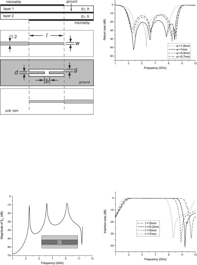
Figure 1 The geometry of the proposed filter
2. FILTER DESIGN
Figure 1 shows the geometry of the proposed UWB filter on the substrates both with r 3.48 and h 0.508 mm. The two 50 microstrip feeding lines of 1.2 mm wide are located on the top surface of the layer 1 and the bottom surface of the layer 2, respectively. The two w-wide microstrip line resonators are connected to the feeding lines. An H-shaped slot is located on the ground, forming two short-circuited CPWs. The arm width of the H-shaped slot is g. The signal strip width of the two CPWs is d and the width of the gap between the two strips is b. The H-shaped slot and the microstrip line resonators have the same length l.
The resonant response of the proposed resonator structure using weak I/O couplings is shown in Figure 2, which is obtained using
Figure 3 The return losses of the filter with different w, other parameters use the optimized values
HFSS. It is observed that three resonant peaks are extracted and almost equally spaced within the UWB passband. Figure 3 shows the simulated return losses of the filter with different width w. When w equals 1 mm, the filter has the best return loss in the UWB band, better than 18 dB in the passband. Since the vertical coupling achieves very tight coupling degree [6], the simulated results show an excellent return loss performance in the UWB band. Figure 4 plots the insertion losses of the filter with different length l. As l decreases, the lower end frequency of the passband increases slowly and the upper end one increases quickly. This means that the filters with different length l have different bandwidth. Moreover, the lower end frequency can also be shifted up by decreasing the width d or by increasing the width g. It is noted that the higher end frequency of the passband is almost unchanged when d or g varies [4]. In this design, a filter with l 14.2 mm, g 1 mm, b 2 mm, w 1 mm, and d 0.3 mm achieves the best simulated performance, as shown in Figures 3 and 4 using the solid lines. The simulated results show that the bandpass filter has a very good in-band performance.
3. EXPERIMENTAL RESULTS
As shown in Figure 5, a test UWB bandpass filter was fabricated and measured. The two substrate layers are combined using plastic
|
Figure 4 The insertion losses of the filter with different l, other param- |
Figure 2 The resonant response of the proposed resonator structure |
eters use the optimized values |
1050 |
MICROWAVE AND OPTICAL TECHNOLOGY LETTERS / Vol. 49, No. 5, May 2007 |
DOI 10.1002/mop |
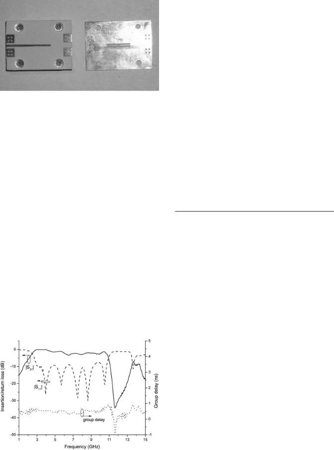
Figure 5 Photograph of the proposed filter
bolts. The measured return loss, insertion loss, and group delay are plotted in Figure 6. The measured results show that the filter has a passband from 2.6 to 10.7 GHz, a little wider than the released UWB band. The measured return loss is lower than the simulated one and the measured insertion loss is about 2–3.3 dB from 6 to 10 GHz. The discrepancies are mainly caused by the connection of the SMA connectors during the measurement. The measured group delay is about 0.31– 0.77 ns. Five transmission poles in the passband and a transmission zero at 11.6 GHz are showed in the measured results, which are in good agreement with the theoretical prediction. The overall length of the proposed UWB filter is 14.2 mm, about a half guided wavelength at 6.85 GHz, which is smaller than that reported in Refs.6, 7.
4. CONCLUSION
A novel full band UWB bandpass filter using a two-layered substrate is presented. By using the vertical coupling through an H-shaped slot on the ground between the microstrip line resonator and short-circuited CPW on the ground, a UWB filter with an overall length of about a half guided wavelength at the center UWB frequency has been achieved. By improving the qualities of fabrication and measurement, the proposed filter is promising to be developed into a compact multilayered bandpass filter for the UWB applications.
ACKNOWLEDGMENT
Xinan Qu thank Prof. K. Li of National Institute of Information and Communications Technology of Japan and P. Cai and X.-H.
Figure 6 Measured results
Guan of Shanghai University for their inspiring discussions on microwave planar filters.
REFERENCES
1.Revision of part 15 of the commission’s rules regarding ultra-wideband transmission systems, First note and Order, Federal Communications Commission, ET-Docket 98 –153, February 14, 2002, Available at http://www.fcc.gov/Bureaus/Engineering Technology/Orders/2002/ fcc02048.pdf.
2.H. Ishida and K. Araki, Design and analysis of UWB band pass filter with ring filter, IEEE MTT-S Int Microwave Symp Dig, Fort Worth, TX, 2004, pp. 1307–1310.
3.W.-T. Wong, Y.-S. Lin, C.-H. Wang, and C.H. Chen, Highly selective microstrip bandpass filters for ultra-wideband (UWB) applications,
Asia-Pacific Microwave Conference Suzhou, China, 2005, pp. 1– 4.
4.L. Zhu and W. Menzel, Broad-band microstrip-to-cpw transition via frequency-dependent electromagnetic coupling, IEEE Trans Microwave Theory Tech 52 (2004), 1517–1522.
5.K. Li, D. Kurita, and T. Matsui, A novel UWB bandpass filter and its application to UWB pulse generation, IEEE International Conference on Ultra-Wideband, Zurich, Switzerland, 2005, pp. 446 – 451.
6.H. Wang and L. Zhu, Ultra-wideband bandpass filter using back-to-back microstrip-to-cpw transition structure, Electron Lett 41 (2005), 1337– 1338.
7.H. Wang, L. Zhu, and W. Menzel, Ultra-wideband bandpass filter with hybrid microstrip/cpw structure, IEEE Microwave Wireless Component Lett 15 (2005), 844 – 846.
© 2007 Wiley Periodicals, Inc.
COUPLED-MODE ANALYSIS OF NONLINEAR FIBER COUPLERS WITH DIFFERENT CORE PARAMETERS
Min Liu
College of Communication Engineering, Chongqing University,
Chongqing 400044, People’s Republic of China
Received 30 September 2006
ABSTRACT: A nonlinear two-core fiber coupler with unequal cores (phase-mismatched) is analyzed by using coupled-mode theory. Based on the solutions of the coupled-mode equations, it is demonstrated that even though there is a difference in core diameter, the unequal-core fiber coupler (phase-mismatched) can function as a twin-core fiber coupler (phasematched) by increasing the refractive index of the small core. © 2007 Wiley Periodicals, Inc. Microwave Opt Technol Lett 49: 1051–1053, 2007; Published online in Wiley InterScience (www.interscience.wiley.com). DOI 10.1002/mop.22350
Key words: directional coupler; two-core fiber; pulse switching; unequal cores
1. INTRODUCTION
Since Snyder pioneered the study of coupled-mode theory in cylindrical optical-fiber systems in 1972 [1], the optical coupling between two parallel optical waveguides has been a matter of scientific concern. Two-core fiber couplers, especially, have been investigated extensively since the success of producing a two-core fiber functioning as a directional coupler in 1980 [2]. The wavelength and polarization selectivity of two-core fibers can find many applications. The nonlinear properties of the two-core fiber coupler were also inspected with the realization of an ultrafast all-optical switch [3]. Many useful devices can be constructed from two-core couplers, such as optical switches and wavelength-selectors.
DOI 10.1002/mop |
MICROWAVE AND OPTICAL TECHNOLOGY LETTERS / Vol. 49, No. 5, May 2007 |
1051 |