

- •1 System and Memory
- •1.1 Introduction
- •1.2 Features
- •1.3 Functional Description
- •1.3.1 Address Mapping
- •1.3.2 Embedded Memory
- •1.3.3 External Memory
- •1.3.5 Peripherals
- •2 Interrupt Matrix (INTERRUPT)
- •2.1 Overview
- •2.2 Features
- •2.3 Functional Description
- •2.3.1 Peripheral Interrupt Source
- •2.3.2 CPU Interrupt
- •2.3.3 Allocate Peripheral Interrupt Sources to Peripheral Interrupt on CPU
- •2.3.4 CPU NMI Interrupt Mask
- •2.3.5 Query Current Interrupt Status of Peripheral Interrupt Source
- •2.4 Registers
- •3 Reset and Clock
- •3.1 System Reset
- •3.1.1 Introduction
- •3.1.2 Reset Source
- •3.2 System Clock
- •3.2.1 Introduction
- •3.2.3 CPU Clock
- •3.2.4 Peripheral Clock
- •3.2.7 Audio PLL
- •3.3 Register Summary
- •3.4 Registers
- •4.1 Overview
- •4.2 Peripheral Input via GPIO Matrix
- •4.2.1 Summary
- •4.2.2 Functional Description
- •4.2.3 Simple GPIO Input
- •4.3 Peripheral Output via GPIO Matrix
- •4.3.1 Summary
- •4.3.3 Simple GPIO Output
- •4.4 Direct I/O via IO_MUX
- •4.4.1 Summary
- •4.4.2 Functional Description
- •4.5 RTC IO_MUX for Low Power and Analog I/O
- •4.5.1 Summary
- •4.5.2 Analog Function Description
- •4.7 Pad Hold Feature
- •4.8 I/O Pad Power Supplies
- •4.8.1 VDD_SDIO Power Domain
- •4.9 Peripheral Signal List
- •4.10 IO_MUX Pad List
- •4.11 RTC_MUX Pin List
- •4.12 Register Summary
- •4.12.1 GPIO Matrix Register Summary
- •4.12.2 IO MUX Register Summary
- •4.12.3 RTC IO MUX Register Summary
- •4.13 Registers
- •4.13.1 GPIO Matrix Registers
- •4.13.2 IO MUX Registers
- •4.13.3 RTC IO MUX Registers
- •5 DPort Registers
- •5.1 Introduction
- •5.2 Features
- •5.3 Functional Description
- •5.3.1 System and Memory Register
- •5.3.2 Reset and Clock Registers
- •5.3.3 Interrupt Matrix Register
- •5.3.4 DMA Registers
- •5.3.5 MPU/MMU Registers
- •5.3.7 Peripheral Clock Gating and Reset
- •5.4 Register Summary
- •5.5 Registers
- •6 DMA Controller (DMA)
- •6.1 Overview
- •6.2 Features
- •6.3 Functional Description
- •6.3.1 DMA Engine Architecture
- •6.3.2 Linked List
- •6.4 UART DMA (UDMA)
- •7 SPI Controller (SPI)
- •7.1 Overview
- •7.5 Parallel QSPI
- •7.5.1 Communication Format of Parallel QSPI
- •7.6.1 SPI Interrupts
- •7.6.2 DMA Interrupts
- •7.7 Register Summary
- •7.8 Registers
- •8 SDIO Slave Controller
- •8.1 Overview
- •8.2 Features
- •8.3 Functional Description
- •8.3.1 SDIO Slave Block Diagram
- •8.3.3 Register Access
- •8.3.6 SDIO Bus Timing
- •8.3.7 Interrupt
- •8.4 Register Summary
- •8.5 SLC Registers
- •8.6 SLC Host Registers
- •8.7 HINF Registers
- •9 SD/MMC Host Controller
- •9.1 Overview
- •9.2 Features
- •9.3 SD/MMC External Interface Signals
- •9.4 Functional Description
- •9.4.1 SD/MMC Host Controller Architecture
- •9.4.2 Command Path
- •9.4.3 Data Path
- •9.5 Software Restrictions for Proper CIU Operation
- •9.6 RAM for Receiving and Sending Data
- •9.6.1 Transmit RAM Module
- •9.6.2 Receive RAM Module
- •9.8 The Structure of a Linked List
- •9.9 Initialization
- •9.9.1 DMAC Initialization
- •9.9.2 DMAC Transmission Initialization
- •9.9.3 DMAC Reception Initialization
- •9.11 Interrupt
- •9.12 Register Summary
- •9.13 Registers
- •10 Ethernet Media Access Controller (MAC)
- •10.1 Overview
- •10.2 EMAC_CORE
- •10.2.1 Transmit Operation
- •10.2.2 Receive Operation
- •10.3 MAC Interrupt Controller
- •10.4 MAC Address Filtering
- •10.4.1 Unicast Destination Address Filtering
- •10.4.2 Multicast Destination Address Filtering
- •10.4.3 Broadcast Address Filtering
- •10.4.4 Unicast Source Address Filtering
- •10.4.5 Inverse Filtering Operation
- •10.4.6 Good Transmitted Frames and Received Frames
- •10.5 EMAC_MTL (MAC Transaction Layer)
- •10.6 PHY Interface
- •10.6.1 MII (Media Independent Interface)
- •10.6.3 Station Management Agent (SMA) Interface
- •10.6.4 RMII Timing
- •10.7 Ethernet DMA Features
- •10.8 Linked List Descriptors
- •10.8.1 Transmit Descriptors
- •10.8.2 Receive Descriptors
- •10.9 Register Summary
- •10.10 Registers
- •11 I2C Controller (I2C)
- •11.1 Overview
- •11.2 Features
- •11.3 Functional Description
- •11.3.1 Introduction
- •11.3.2 Architecture
- •11.3.3 I2C Bus Timing
- •11.3.7 Interrupts
- •11.4 Register Summary
- •11.5 Registers
- •12 I2S Controller (I2S)
- •12.1 Overview
- •12.2 Features
- •12.3 The Clock of I2S Module
- •12.4 I2S Mode
- •12.4.1 Supported Audio Standards
- •12.4.2 Module Reset
- •12.4.3 FIFO Operation
- •12.4.5 Receiving Data
- •12.5.1 LCD Master Transmitting Mode
- •12.5.2 Camera Slave Receiving Mode
- •12.5.3 ADC/DAC mode
- •12.6 I2S Interrupts
- •12.6.1 FIFO Interrupts
- •12.6.2 DMA Interrupts
- •12.7 Register Summary
- •12.8 Registers
- •13 UART Controller (UART)
- •13.1 Overview
- •13.2 UART Features
- •13.3 Functional Description
- •13.3.1 Introduction
- •13.3.3 UART RAM
- •13.3.5 UART Data Frame
- •13.3.7 Flow Control
- •13.3.8 UART DMA
- •13.3.9 UART Interrupts
- •13.3.10 UHCI Interrupts
- •13.4 Register Summary
- •13.4.1 UART Register Summary
- •13.5 Registers
- •13.5.1 UART Registers
- •13.5.2 UHCI Registers
- •14 LED PWM Controller (LEDC)
- •14.1 Introduction
- •14.2 Functional Description
- •14.2.1 Architecture
- •14.2.3 Channels
- •14.2.4 Interrupts
- •14.3 Register Summary
- •14.4 Registers
- •15 Remote Control Peripheral (RMT)
- •15.1 Introduction
- •15.2 Functional Description
- •15.2.1 RMT Architecture
- •15.2.3 Clock
- •15.2.4 Transmitter
- •15.2.5 Receiver
- •15.2.6 Interrupts
- •15.3 Register Summary
- •15.4 Registers
- •16 Motor Control PWM (PWM)
- •16.1 Introduction
- •16.2 Features
- •16.3 Submodules
- •16.3.1 Overview
- •16.3.2 PWM Timer Submodule
- •16.3.3 PWM Operator Submodule
- •16.3.4 Capture Submodule
- •16.4 Register Summary
- •16.5 Registers
- •17 Pulse Count Controller (PCNT)
- •17.1 Overview
- •17.2 Functional Description
- •17.2.1 Architecture
- •17.2.2 Counter Channel Inputs
- •17.2.3 Watchpoints
- •17.2.4 Examples
- •17.2.5 Interrupts
- •18 Timer Group (TIMG)
- •18.1 Introduction
- •18.2 Functional Description
- •18.2.2 64-bit Time-base Counter
- •18.2.3 Alarm Generation
- •18.2.4 MWDT
- •18.2.5 Interrupts
- •18.3 Register Summary
- •18.4 Registers
- •19 Watchdog Timers (WDT)
- •19.1 Introduction
- •19.2 Features
- •19.3 Functional Description
- •19.3.1 Clock
- •20 eFuse Controller
- •20.1 Introduction
- •20.2 Features
- •20.3 Functional Description
- •20.3.1 Structure
- •20.3.3 Software Reading of System Parameters
- •20.3.4 The Use of System Parameters by Hardware Modules
- •20.3.5 Interrupts
- •20.4 Register Summary
- •20.5 Registers
- •21 Two-wire Automotive Interface (TWAI)
- •21.1 Overview
- •21.2 Features
- •21.3 Functional Protocol
- •21.3.1 TWAI Properties
- •21.3.2 TWAI Messages
- •21.3.3 TWAI Errors
- •21.3.4 TWAI Bit Timing
- •21.4 Architectural Overview
- •21.4.1 Registers Block
- •21.4.2 Bit Stream Processor
- •21.4.3 Error Management Logic
- •21.4.4 Bit Timing Logic
- •21.4.5 Acceptance Filter
- •21.5 Functional Description
- •21.5.1 Modes
- •21.5.2 Bit Timing
- •21.5.3 Interrupt Management
- •21.5.4 Transmit and Receive Buffers
- •21.5.5 Receive FIFO and Data Overruns
- •21.5.6 Acceptance Filter
- •21.5.8 Error Code Capture
- •21.5.9 Arbitration Lost Capture
- •21.6 Register Summary
- •21.7 Registers
- •22 AES Accelerator (AES)
- •22.1 Introduction
- •22.2 Features
- •22.3 Functional Description
- •22.3.1 AES Algorithm Operations
- •22.3.2 Key, Plaintext and Ciphertext
- •22.3.3 Endianness
- •22.3.4 Encryption and Decryption Operations
- •22.3.5 Speed
- •22.4 Register Summary
- •22.5 Registers
- •23 SHA Accelerator (SHA)
- •23.1 Introduction
- •23.2 Features
- •23.3 Functional Description
- •23.3.1 Padding and Parsing the Message
- •23.3.2 Message Digest
- •23.3.3 Hash Operation
- •23.3.4 Speed
- •23.4 Register Summary
- •23.5 Registers
- •24 RSA Accelerator (RSA)
- •24.1 Introduction
- •24.2 Features
- •24.3 Functional Description
- •24.3.1 Initialization
- •24.3.2 Large Number Modular Exponentiation
- •24.3.4 Large Number Multiplication
- •24.4 Register Summary
- •24.5 Registers
- •25 Random Number Generator (RNG)
- •25.1 Introduction
- •25.2 Feature
- •25.3 Functional Description
- •25.5 Register Summary
- •25.6 Register
- •26 External Memory Encryption and Decryption (FLASH)
- •26.1 Overview
- •26.2 Features
- •26.3 Functional Description
- •26.3.1 Key Generator
- •26.3.2 Flash Encryption Block
- •26.3.3 Flash Decryption Block
- •26.4 Register Summary
- •26.5 Register
- •27 Memory Management and Protection Units (MMU, MPU)
- •27.1 Introduction
- •27.2 Features
- •27.3 Functional Description
- •27.3.1 PID Controller
- •28 Process ID Controller (PID)
- •28.1 Overview
- •28.2 Features
- •28.3 Functional Description
- •28.3.1 Interrupt Identification
- •28.3.2 Information Recording
- •28.3.3 Proactive Process Switching
- •28.4 Register Summary
- •28.5 Registers
- •29 On-Chip Sensors and Analog Signal Processing
- •29.1 Introduction
- •29.2 Capacitive Touch Sensor
- •29.2.1 Introduction
- •29.2.2 Features
- •29.2.3 Available GPIOs
- •29.2.4 Functional Description
- •29.2.5 Touch FSM
- •29.3.1 Introduction
- •29.3.2 Features
- •29.3.3 Outline of Function
- •29.3.4 RTC SAR ADC Controllers
- •29.3.5 DIG SAR ADC Controllers
- •29.4.1 Introduction
- •29.4.2 Features
- •29.4.4 Cosine Waveform Generator
- •29.5 Register Summary
- •29.5.1 Sensors
- •29.5.2 Advanced Peripheral Bus
- •29.6 Registers
- •29.6.1 Sensors
- •29.6.2 Advanced Peripheral Bus
- •30 ULP Coprocessor (ULP)
- •30.1 Introduction
- •30.2 Features
- •30.4 Instruction Set
- •30.4.2 ST – Store Data in Memory
- •30.4.3 LD – Load Data from Memory
- •30.4.4 JUMP – Jump to an Absolute Address
- •30.4.5 JUMPR – Jump to a Relative Offset (Conditional upon R0)
- •30.4.7 HALT – End the Program
- •30.4.8 WAKE – Wake up the Chip
- •30.4.10 WAIT – Wait for a Number of Cycles
- •30.4.12 I2C_RD/I2C_WR – Read/Write I²C
- •30.4.13 REG_RD – Read from Peripheral Register
- •30.5 ULP Program Execution
- •30.6 RTC_I2C Controller
- •30.6.1 Configuring RTC_I2C
- •30.6.2 Using RTC_I2C
- •30.7 Register Summary
- •30.7.1 SENS_ULP Address Space
- •30.7.2 RTC_I2C Address Space
- •30.8 Registers
- •30.8.1 SENS_ULP Address Space
- •30.8.2 RTC_I2C Address Space
- •31 Low-Power Management (RTC_CNTL)
- •31.1 Introduction
- •31.2 Features
- •31.3 Functional Description
- •31.3.2 Digital Core Voltage Regulator
- •31.3.4 Flash Voltage Regulator
- •31.3.5 Brownout Detector
- •31.3.6 RTC Module
- •31.3.9 Predefined Power Modes
- •31.3.10 Wakeup Source
- •31.3.12 RTC Timer
- •31.3.13 RTC Boot
- •31.4 Register Summary
- •31.5 Registers
- •Glossary
- •Abbreviations for Peripherals
- •Abbreviations for Registers
- •Revision History

11 I2C Controller (I2C)
11 I2C Controller (I2C)
11.1Overview
An I2C (Inter-Integrated Circuit) bus can be used for communication with several external devices connected to the same bus as ESP32. The ESP32 has dedicated hardware to communicate with peripherals on the I2C bus.
11.2Features
The I2C controller has the following features:
•Supports both master mode and slave mode
•Supports multi-master and multi-slave communication
•Supports standard mode (100 kbit/s)
•Supports fast mode (400 kbit/s)
•Supports 7-bit addressing and 10-bit addressing
•Supports continuous data transmission with disabled Serial Clock Line (SCL)
•Supports programmable digital noise filter
11.3Functional Description
11.3.1 Introduction
I2C is a two-wire bus, consisting of an SDA and an SCL line. These lines are configured to open the drain output. The lines are shared by two or more devices: usually one or more masters and one or more slaves.
Communication starts when a master sends out a start condition: it will pull the SDA line low, and will then pull the SCL line high. It will send out nine clock pulses over the SCL line. The first eight pulses are used to shift out a byte consisting of a 7-bit address and a read/write bit. If a slave with this address is active on the bus, the slave can answer by pulling the SDA low on the ninth clock pulse. The master can then send out more 9-bit clock pulse clusters and, depending on the read/write bit sent, the device or the master will shift out data on the SDA line, with the other side acknowledging the transfer by pulling the SDA low on the ninth clock pulse. During data transfer, the SDA line changes only when the SCL line is low. When the master has finished the communication, it will send a stop condition on the bus by raising SDA, while SCL will already be high.
The ESP32 I2C peripheral can handle the I2C protocol, freeing up the processor cores for other tasks.
Espressif Systems |
284 |
ESP32 TRM (Version 5.0) |
Submit Documentation Feedback

11 I2C Controller (I2C)
11.3.2 Architecture
An I2C controller can operate either in master mode or slave mode. The I2C_MS_MODE register is used to select the mode. Figure 11-1 shows the I2C Master architecture, while Figure 11-2 shows the I2C Slave architecture.
Figure 111. I2C Master Architecture
Figure 112. I2C Slave Architecture
The I2C controller contains the following units:
•RAM, the size of which is 32 x 8 bits, and it is directly mapped onto the address space of the CPU cores, starting at address REG_I2C_BASE+0x100. Each byte of I2C data is stored in a 32-bit word of memory (so, the first byte is at +0x100, the second byte at +0x104, the third byte at +0x108, etc.) Users need to set register I2C_NONFIFO_EN.
•A CMD_Controller and 16 command registers (cmd0 ~ cmd15), which are used by the I2C Master to control data transmission. One command at a time is executed by the I2C controller.
•SCL_FSM: A state machine that controls the SCL clock. The I2C_SCL_HIGH_PERIOD_REG and I2C_SCL_ LOW_PERIOD_REG registers are used to configure the frequency and duty cycle of the signal on the SCL line.
•SDA_FSM: A state machine that controls the SDA data line.
Espressif Systems |
285 |
ESP32 TRM (Version 5.0) |
Submit Documentation Feedback

11I2C Controller (I2C)
•DATA_Shifter which converts the byte data to an outgoing bitstream, or converts an incoming bitstream to byte data. I2C_RX_LSB_FIRST and I2C_TX_LSB_FIRST can be used for configuring whether the LSB or MSB is stored or transmitted first.
•SCL_Filter and SDA_Filter: Input noise filter for the I2C_Slave. The filter can be enabled or disabled by configuring I2C_SCL_FILTER_EN and I2C_SDA_FILTER_EN. The filter can remove line glitches with pulse width less than I2C_SCL_FILTER_THRES and I2C_SDA_FILTER_THRES ABP clock cycles.
11.3.3 I2C Bus Timing
Figure 113. I2C Sequence Chart
Figure 11-3 is an I2C sequence chart. When the I2C controller works in master mode, SCL is an output signal. In contrast, when the I2C controller works in slave mode, the SCL becomes an input signal. The values assigned to I2C_SDA_HOLD_REG and I2C_SDA_SAMPLE_REG are still valid in slave mode. Users need to configure the values of I2C_SDA_HOLD_TIME and I2C_SDA_SAMPLE_TIME, according to the host characteristics, for the I2C slave to receive data properly. Table 11-1 shows available settings of SCL low and high level cycles when SCL is configured to direct output mode. The settings determine the SCL output frequency fscl.
Table 111. SCL Frequency Configuration
I2C_SCL_FILTER_EN |
I2C_SCL_FILTER_THRES |
SCL_Low_Level_Cycles |
SCL_High_Level_Cycles |
0 |
Don’t care |
|
I2C_SCL_HIGH_PERIOD+7 |
|
|
|
|
1 |
[0,2] |
I2C_SCL_LOW_PERIOD+1 |
I2C_SCL_HIGH_PERIOD+8 |
|
|
|
|
[3,7] |
|
I2C_SCL_HIGH_PERIOD+6+I2C_SCL_FILTER_THRES |
|
|
|
||
|
|
|
|
80 MHz
fscl = SCL_Low_Level_Cycles + SCL_High_Level_Cycles
According to the I2C protocol, each transmission of data begins with a START condition and ends with a STOP condition. Data is transmitted by one byte at a time, and each byte has an ACK bit. The receiver informs the transmitter to continue transmission by pulling down SDA, which indicates an ACK. The receiver can also indicate it wants to stop further transmission by pulling up the SDA line, thereby not indicating an ACK.
Figure 11-3 also shows the registers that can configure the START bit, STOP bit, SDA hold time, and SDA sample time.
Notice: If the I2C pads are configured in open-drain mode, it will take longer for the signal lines to transition from a low level to a high level. The transition duration is determined together by the pull-up resistor and capacitor. The output frequency of SCL is relatively low in open-drain mode.
Espressif Systems |
286 |
ESP32 TRM (Version 5.0) |
Submit Documentation Feedback

11 I2C Controller (I2C)
11.3.4 I2C cmd Structure
Figure 114. Structure of The I2C Command Register
The Command register is active only in I2C master mode, with its internal structure shown in Figure 11-4.
CMD_DONE: The CMD_DONE bit of every command can be read by software to tell if the command has been handled by hardware.
op_code: op_code is used to indicate the command. The I2C controller supports four commands:
•RSTART: op_code = 0 is the RSTART command to control the transmission of a START or RESTART I2C condition.
•WRITE: op_code = 1 is the WRITE command for the I2C Master to transmit data.
•READ: op_code = 2 is the READ command for the I2C Master to receive data.
•STOP: op_code = 3 is the STOP command to control the transmission of a STOP I2C condition.
•END: op_code = 4 is the END command for continuous data transmission. When the END command is given, SCL is temporarily disabled to allow software to reload the command and data registers for subsequent events before resuming. Transmission will then continue seamlessly.
A complete data transmission process begins with an RSTART command, and ends with a STOP command.
ack_value: When receiving data, this bit is used to indicate whether the receiver will send an ACK after this byte has been received.
ack_exp: This bit is to set an expected ACK value for the transmitter.
ack_check_en: When transmitting a byte, this bit enables checking the ACK value received against the ack_exp value. Checking is enabled by 1, while 0 disables it.
byte_num: This register specifies the length of data (in bytes) to be read or written. The maximum length is 255, while the minimum is 1. When the op_code is RSTART, STOP or END, this value is meaningless.
Espressif Systems |
287 |
ESP32 TRM (Version 5.0) |
Submit Documentation Feedback

11 I2C Controller (I2C)
11.3.5 I2C Master Writes to Slave
Figure 115. I2C Master Writes to Slave with 7bit Address
In all subsequent figures that illustrate I2C transactions and behavior, both the I2C Master and Slave devices are assumed to be ESP32 I2C peripheral controllers for ease of demonstration.
Figure 11-5 shows the I2C Master writing N bytes of data to an I2C Slave. According to the I2C protocol, the first byte is the Slave address. As shown in the diagram, the first byte of the RAM unit has been populated with the Slave’s 7-bit address plus the 1-bit read/write flag. In this case, the flag is zero, indicating a write operation. The rest of the RAM unit holds N bytes of data ready for transmission. The cmd unit has been populated with the sequence of commands for the operation.
For the I2C master to begin an operation, the bus must not be busy, i.e. the SCL line must not be pulled low by another device on the I2C bus. The I2C operation can only begin when the SCL line is released (made high) to indicate that the I2C bus is free. After the cmd unit and data are prepared, I2C_TRANS_START bit in I2C_CTR_REG must be set to begin the configured I2C Master operation. The I2C Master then initiates a START condition on the bus and progresses to the WRITE command which will fetch N+1 bytes from RAM and send them to the Slave. The first of these bytes is the address byte.
When the transmitted data size exceeds I2C_NONFIFO_TX_THRES, an I2C_TX_SEND_EMPTY_INT interrupt will be generated. After detecting the interrupt, software can read TXFIFO_END_ADDR in register RXFIFO_ST_REG, get the last address of the data in the RAM and refresh the old data in the RAM. TXFIFO_END_ADDR will be refreshed each time interrupt I2C_TX_SEND_EMPTY_INT or I2C_TRANS_COMPLETE_INT occurs.
When ack_check_en is set to 1, the Master will check the ACK value each time it sends a data byte. If the ACK value received does not match ack_exp (the expected ACK value) in the WRITE command, then the Master will generate an I2C_ACK_ERR_INT interrupt and stop the transmission.
During transmission, when the SCL is high, if the input value and output value of SDA do not match, then the Master will generate an I2C_ARBITRATION_LOST_INT interrupt. When the transmission is finished, the Master will generate an I2C_TRANS_COMPLETE_INT interrupt.
After detecting the START bit sent from the Master, the Slave will start receiving the address and comparing it to its own. If the address does not match I2C_SLAVE_ADDR, then the Slave will ignore the rest of the transmission. If they do match, the Slave will store the rest of the data into RAM in the receiving order. When the data size exceeds I2C_NONFIFO_RX_THRES, an I2C_RX_REC_FULL_INT interrupt is generated. After detecting the
Espressif Systems |
288 |
ESP32 TRM (Version 5.0) |
Submit Documentation Feedback

11 I2C Controller (I2C)
interrupt, software will get the starting and ending addresses in the RAM by reading RXFIFO_START_ADDR and RXFIFO_END_ADDR bits in register RXFIFO_ST_REG, and fetch the data for further processing. Register RXFIFO_START_ADDR is refreshed only once during each transmission, while RXFIFO_END_ADDR gets refreshed every time when either I2C_RX_REC_FULL_INT or I2C_TRANS_COMPLETE_INT interrupt is generated.
When the END command is not used, the I2C master can transmit up to (14*255-1) bytes of valid data, and the cmd unit is populated with RSTART + 14 WRITE + 1 STOP.
There are several special cases to be noted:
•If the Master fails to send a STOP bit, because the SDA is pulled low by other devices, then the Master needs to be reset.
•If the Master fails to send a START bit, because the SDA or SCL is pulled low by other devices, then the Master needs to be reset. It is recommended that the software uses a timeout period to implement the reset.
•If the SDA is pulled low by the Slave during transmission, the Master can simply release it by sending it nine SCL clock signals at the most.
It is important to note that the behaviour of another I2C master or slave device on the bus may not always be similar to that of the ESP32 I2C peripheral in the masteror slave-mode operation described above. Please consult the datasheets of the respective I2C devices to ensure proper operation under all bus conditions.
The ESP32 I2C controller uses 7-bit addressing by default. However, 10-bit addressing can also be used. In the master, this is done by sending a second I2C address byte after the first address byte. In the slave, the I2C_SLAVE_ADDR_10BIT_EN bit in I2C_SLAVE_ADDR_REG can be set to activate a 10-bit addressing mode. I2C_SLAVE_ADDR is used to configure the I2C Slave address, as per usual. Figure 11-6 shows the equivalent of I2C Master operation writing N-bytes of data to an I2C Slave with a 10-bit address. Since 10-bit Slave addresses require an extra address byte, both the byte_num field of the WRITE command and the number of total bytes in RAM increase by one.
Figure 116. I2C Master Writes to Slave with 10bit Address
When the END command is not used, the I2C master can transmit up to (14*255-2) bytes of valid data to Slave with 10-bit address.
One way many I2C Slave devices are designed is by exposing a register block containing various settings. The I2C Master can write one or more of these registers by sending the Slave a register address. The ESP32 I2C Slave controller has hardware support for such a scheme.
Espressif Systems |
289 |
ESP32 TRM (Version 5.0) |
Submit Documentation Feedback
11 I2C Controller (I2C)
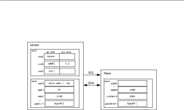
Specifically, on the Slave, I2C_FIFO_ADDR_CFG_EN can be set so that the I2C Master can write to a specified register address inside the I2C Slave memory block. Figure 11-7 shows the Master writing N-bytes of data byte0 ~ byte(N-1) from the RAM unit to register address M (determined by addrM in RAM unit) with the Slave. In this mode, Slave can receive up to 32 bytes of valid data. When Master needs to transmit extra amount of data, segmented transmission can be enabled.
Figure 117. I2C Master Writes to addrM in RAM of Slave with 7bit Address
If the data size exceeds the capacity of a 14-byte read/write cmd, the END command can be called to enable segmented transmission. Figure 11-8 shows the Master writing data to the Slave, in three segments. The first segment shows the configuration of the Master’s commands and the preparation of data in the RAM unit. When the I2C_TRANS_START bit is enabled, the Master starts transmission. After executing the END command, the Master will turn off the SCL clock and pull the SCL low to reserve the bus and prevent any other device from transacting on the bus. The controller will generate an I2C_END_DETECT_INT interrupt to notify the software.
Espressif Systems |
290 |
ESP32 TRM (Version 5.0) |
Submit Documentation Feedback
11 I2C Controller (I2C)
Figure 118. Master Writes to Slave with 7bit Address in Three Segments
After detecting an I2C_END_DETECT_INT interrupt, the software can refresh the contents of the cmd and RAM blocks, as shown in the second segment. Subsequently, it should clear the I2C_END_DETECT_INT interrupt and resume the transaction by setting the I2C_TRANS_START bit. To stop the transaction, it should configure the cmd, as the third segment shows, and enable the I2C_TRANS_START bit to generate a STOP bit, after detecting the I2C_END_DETECT_INT interrupt.
Please note that the other masters on the bus will be starved of bus time between two segments. The bus is only released after a STOP signal is sent.
Note: When there are more than three segments, the address of an END command in the cmd should not be altered into another command by the next segment.
Espressif Systems |
291 |
ESP32 TRM (Version 5.0) |
Submit Documentation Feedback
11 I2C Controller (I2C)
11.3.6Master Reads from Slave
Figure 119. Master Reads from Slave with 7bit Address
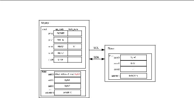
Figure 11-9 shows the Master reading N-bytes of data from an Slave with a 7-bit address. At first, the Master needs to send the address of the Slave, so cmd1 is a WRITE command. The byte that this command sends is the slave address plus the R/W flag, which in this case is 1 and, therefore, indicates that this is going to be a read operation. The Slave starts to send data to the Master if the addresses match. The Master will return ACK, according to the ack_value in the READ command, upon receiving every byte. As can be seen from Figure 11-9, READ is divided into two segments. The Master replies ACK to N-1 bytes in cmd2 and does not reply ACK to the single byte READ command in cmd3, i.e., the last transmitted data. Users can configure it as they wish.
When storing the received data, Master will start from the first address in RAM. Byte0 (Slave address + 1-bit R/W marker bit) will be overwritten.
When the END command is not used, the Master can receive up to (13*255) bytes of valid data. The cmd unit is populated with RSTART + 1 WRITE + 13 READ + 1 STOP.
Figure 11-10 shows the Master reading data from a slave with a 10-bit address. This mode can be enabled by setting I2C_SLAVE_ADDR_10BIT_EN bit and preparing data to be sent in the slave RAM. In the Master, two bytes of RAM are used for a 10-bit address. Finally, the I2C _TRANS_START bit must be set to enable one transaction.
Espressif Systems |
292 |
ESP32 TRM (Version 5.0) |
Submit Documentation Feedback

11 I2C Controller (I2C)
Figure 1110. Master Reads from Slave with 10bit Address
Figure 11-11 shows the Master reading data from a specified address in the Slave. This mode can be enabled by setting I2C_FIFO_ADDR_CFG_EN and preparing the data to be read by the master in the Slave RAM block. Subsequently, the address of the Slave and the address of the specified register (that is, M) have to be determined by the master. Finally, the I2C_TRANS_START bit must be set in the Master to initiate the read operation, following which the Slave will fetch N bytes of data from RAM and send them to the Master.
Figure 1111. Master Reads N Bytes of Data from addrM in Slave with 7bit Address
Figure 11-12 shows the Master reading N+M bytes of data in three segments from the Slave. The first segment shows the configuration of the cmd and the preparation of data in the Slave RAM. When the I2C_TRANS_START bit is enabled, the Master starts the operation. The Master will refresh the cmd after executing the END command. It will clear the I2C_END_DETECT_INT interrupt, set the I2C_TRANS_START bit and resume the transaction. To stop the transaction, the Master will configure the cmd, as the third segment shows, after detecting the I2C_END_DETECT_INT interrupt. After setting the I2C_TRANS_START bit, Master will send a STOP bit to stop the transaction.
Espressif Systems |
293 |
ESP32 TRM (Version 5.0) |
Submit Documentation Feedback