

2 Pins
2.4Strapping Pins
There are five strapping pins:
•MTDI
•GPIO0
•GPIO2
•MTDO
•GPIO5
Software can read the values of these five bits from register ”GPIO_STRAPPING”.
During the chip’s system reset release (power-on-reset, RTC watchdog reset and brownout reset), the latches of the strapping pins sample the voltage level as strapping bits of ”0” or ”1”, and hold these bits until the chip is powered down or shut down. The strapping bits configure the device’s boot mode, the operating voltage of VDD_SDIO and other initial system settings.
Each strapping pin is connected to its internal pull-up/pull-down during the chip reset. Consequently, if a strapping pin is unconnected or the connected external circuit is high-impedance, the internal weak pull-up/pull-down will determine the default input level of the strapping pins.
To change the strapping bit values, users can apply the external pull-down/pull-up resistances, or use the host MCU’s GPIOs to control the voltage level of these pins when powering on the chip.
After reset release, the strapping pins work as normal-function pins.
Refer to Table 2-3 for a detailed boot-mode configuration by strapping pins.
Table 2-3. Strapping Pins
Voltage of Internal LDO (VDD_SDIO)
|
Pin |
|
Default |
3.3 V |
|
1.8 |
V |
|
||||
|
MTDI |
|
Pull-down |
|
0 |
|
1 |
|
|
|||
|
|
|
|
|
|
|
|
|
|
|
|
|
|
|
|
|
Booting Mode |
|
|
|
|
|
|||
|
Pin |
|
Default |
SPI Boot |
|
Download Boot |
|
|||||
|
GPIO0 |
|
Pull-up |
|
1 |
|
0 |
|
|
|||
|
|
|
|
|
|
|
|
|
|
|
|
|
|
GPIO2 |
|
Pull-down |
Don’t-care |
|
0 |
|
|
||||
|
|
|
|
|
|
|
|
|
|
|||
|
|
Enabling/Disabling Debugging Log Print over U0TXD During Booting |
|
|||||||||
|
Pin |
|
Default |
U0TXD Active |
|
U0TXD Silent |
|
|||||
|
MTDO |
|
Pull-up |
|
1 |
|
0 |
|
|
|||
|
|
|
|
|
|
|
|
|
|
|
|
|
|
|
|
|
Timing of SDIO Slave |
|
|
|
|
|
|||
|
|
|
|
FE Sampling |
|
|
FE Sampling |
|
RE Sampling |
|
RE Sampling |
|
|
Pin |
|
Default |
FE Output |
|
|
RE Output |
|
FE Output |
|
RE Output |
|
|
MTDO |
|
Pull-up |
0 |
|
|
0 |
|
1 |
|
1 |
|
|
|
|
|
|
|
|
|
|
|
|
|
|
|
GPIO5 |
|
Pull-up |
0 |
|
|
1 |
|
0 |
|
1 |
|
|
|
|
|
|
|
|
|
|
|
|
|
|
Espressif Systems |
20 |
ESP32 Series Datasheet v4.3 |
Submit Documentation Feedback
2 Pins
Note:
•FE: falling-edge, RE: rising-edge.
•Firmware can configure register bits to change the settings of “Voltage of Internal LDO (VDD_SDIO)” and “Timing of SDIO Slave”, after booting.
•For ESP32 chips that contain an in-package flash or PSRAM, users need to note the logic level of MTDI. For example, ESP32-U4WDH contains an in-package flash that operates at 3.3 V, therefore, the MTDI should be low.
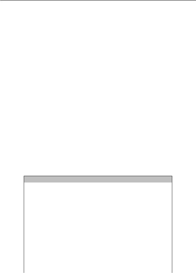
Regarding the timing requirements for the strapping pins, there are such parameters as setup time and hold time. For more information, see Table 2-4 and Figure 2-5.
Table 2-4. Description of Timing Parameters for the Strapping Pins
Parameter |
Description |
|
|
|
|
Min (ms) |
|||
tSU |
Setup time is the time reserved for the power rails to stabilize before |
0 |
|||||||
the CHIP_PU pin is pulled high to activate the chip. |
|||||||||
|
|
|
|||||||
|
|
|
|
|
|
|
|
||
|
Hold time is the time reserved for the chip to read the strapping pin |
|
|
||||||
tH |
values after CHIP_PU is already high and before these pins start |
1 |
|||||||
|
operating as regular IO pins. |
|
|
|
|
|
|||
|
|
|
|
|
|
|
|
|
|
|
tSU |
|
tH |
|
|
||||
|
|
|
|
|
|
|
|
|
|
|
|
|
|
|
|
|
|
|
|
VIL_nRST
CHIP_PU
VIH
Strapping pin
Figure 2-5. Visualization of Timing Parameters for the Strapping Pins
Espressif Systems |
21 |
ESP32 Series Datasheet v4.3 |
Submit Documentation Feedback

2 Pins
2.5Pin Mapping Between Chip and Flash/PSRAM
Table 2-5 lists the pin-to-pin mapping between the chip and the in-package flash/PSRAM. The chip pins listed here are not recommended for other usage.
For the data port connection between ESP32 and off-package flash/PSRAM please refer to Table 2-6.
Table 2-5. Pin-to-Pin Mapping Between Chip and In-Package Flash/PSRAM
|
ESP32-U4WDH |
|
|
In-Package Flash (4 MB) |
|
|
||
|
SD_DATA_1 |
|
|
IO0/DI |
|
|
||
|
|
|
|
|
|
|
|
|
|
GPIO17 |
|
|
IO1/DO |
|
|
||
|
|
|
|
|
|
|
|
|
|
SD_DATA_0 |
|
|
IO2/WP# |
|
|
||
|
|
|
|
|
|
|
|
|
|
SD_CMD |
|
|
IO3/HOLD# |
|
|
||
|
|
|
|
|
|
|
|
|
|
SD_CLK |
|
|
CLK |
|
|
||
|
|
|
|
|
|
|
|
|
|
GPIO16 |
|
|
CS# |
|
|
||
|
|
|
|
|
|
|
|
|
|
GND |
|
|
VSS |
|
|
||
|
|
|
|
|
|
|
|
|
|
VDD_SDIO1 |
|
|
VDD |
|
|
||
|
ESP32-D0WDR2-V3 |
In-Package PSRAM (2 MB) |
|
|
||||
|
SD_DATA_1 |
|
|
SIO0/SI |
|
|
||
|
|
|
|
|
|
|
|
|
|
SD_DATA_0 |
|
|
SIO1/SO |
|
|
||
|
|
|
|
|
|
|
|
|
|
SD_DATA_3 |
|
|
SIO2 |
|
|
||
|
|
|
|
|
|
|
|
|
|
SD_DATA_2 |
|
|
SIO3 |
|
|
||
|
|
|
|
|
|
|
|
|
|
SD_CLK |
|
|
SCLK |
|
|
||
|
|
|
|
|
|
|
|
|
|
GPIO162 |
|
|
CE# |
|
|
||
|
GND |
|
|
VSS |
|
|
||
|
|
|
|
|
|
|
|
|
|
VDD_SDIO1 |
|
|
VDD |
|
|
||
Table 2-6. Pin-to-Pin Mapping Between Chip and Off-Package Flash/PSRAM |
||||||||
|
|
|
|
|
|
|
|
|
|
|
Chip Pin |
|
Off-Package Flash |
|
|
|
|
|
|
SD_DATA_1/SPID |
|
IO0/DI |
|
|
|
|
|
|
|
|
|
|
|
|
|
|
|
SD_DATA_0/SPIQ |
|
IO1/DO |
|
|
|
|
|
|
|
|
|
|
|
|
|
|
|
SD_DATA_3/SPIWP |
|
IO2/WP# |
|
|
|
|
|
|
|
|
|
|
|
|
|
|
|
SD_DATA_2/SPIHD |
|
IO3/HOLD# |
|
|
|
|
|
|
|
|
|
|
|
|
|
|
|
SD_CLK |
|
CLK |
|
|
|
|
|
|
|
|
|
|
|
|
|
|
|
SD_CMD |
|
CS# |
|
|
|
|
|
|
|
|
|
|
|
|
|
|
|
GND |
|
VSS |
|
|
|
|
|
|
|
|
|
|
|
|
|
|
|
VDD_SDIO |
|
VDD |
|
|
|
|
|
|
|
|
|
|
|
|
|
|
|
Chip Pin |
|
Off-Package PSRAM |
|
|
|
|
|
|
SD_DATA_1 |
|
SIO0/SI |
|
|
|
|
|
|
|
|
|
|
|
|
|
|
|
SD_DATA_0 |
|
SIO1/SO |
|
|
|
|
|
|
|
|
|
|
|
|
|
|
|
SD_DATA_3 |
|
SIO2 |
|
|
|
|
|
|
|
|
|
|
|
|
|
|
|
SD_DATA_2 |
|
SIO3 |
|
|
|
|
|
|
|
|
|
|
|
|
|
|
|
SD_CLK/GPIO173 |
|
SCLK |
|
|
|
|
|
|
|
|
|
Cont’d on next page |
|
|
|
Espressif Systems |
22 |
|
ESP32 Series Datasheet v4.3 |
|||||
Submit Documentation Feedback

2 Pins
Table 2-6 – cont’d from previous page
Chip Pin |
Off-Package PSRAM |
GPIO162 |
CE# |
GND |
VSS |
|
|
VDD_SDIO |
VDD |
|
|
Note:
1.As the in-package flash/PSRAM in ESP32-U4WDH/ESP32-D0WDR2-V3 operates at 3.3 V, VDD_SDIO must be powered by VDD3P3_RTC via a 6 Ω resistor. See Figure 2-3 ESP32 Power Scheme.
2.If GPIO16 is used to connect to PSRAM’s CE# signal, please add a pull-up resistor at the GPIO16 pin. See
ESP32-WROVER-E Datasheet > Figure Schematics of ESP32-WROVER-E.
3.SD_CLK and GPIO17 pins are available to connect to the SCLK signal of external PSRAM.
•If SD_CLK pin is selected, one GPIO (i.e., GPIO17) will be saved. The saved GPIO can be used for other purposes. This connection has passed internal tests, but relevant certification has not been completed.
•Or GPIO17 pin is used to connect to the SCLK signal. This connection has passed relevant certification, see certificates for ESP32-WROVER-E.
Please select the proper pin for your specific applications.
Espressif Systems |
23 |
ESP32 Series Datasheet v4.3 |
Submit Documentation Feedback