- •Product Overview
- •Features
- •Applications
- •1 ESP32 Series Comparison
- •1.1 Nomenclature
- •1.2 Comparison
- •2 Pins
- •2.1 Pin Layout
- •2.2 Pin Overview
- •2.2.1 Restrictions for GPIOs and RTC_GPIOs
- •2.3 Power Supply
- •2.3.1 Power Scheme
- •2.4 Strapping Pins
- •2.5 Pin Mapping Between Chip and Flash/PSRAM
- •3 Functional Description
- •3.1 CPU and Memory
- •3.1.2 Internal Memory
- •3.1.4 Address Mapping Structure
- •3.1.5 Cache
- •3.2 System Clocks
- •3.2.1 CPU Clock
- •3.2.2 RTC Clock
- •3.3.1 Power Management Unit (PMU)
- •3.4 Timers and Watchdogs
- •3.4.1 General Purpose Timers
- •3.4.2 Watchdog Timers
- •3.5 Cryptographic Hardware Accelerators
- •3.6.1 2.4 GHz Receiver
- •3.6.2 2.4 GHz Transmitter
- •3.6.3 Clock Generator
- •3.7 Bluetooth
- •3.7.1 Bluetooth Radio and Baseband
- •3.7.2 Bluetooth Interface
- •3.7.3 Bluetooth Stack
- •3.8.1 General Purpose Input / Output Interface (GPIO)
- •3.8.2 Serial Peripheral Interface (SPI)
- •3.8.3 Universal Asynchronous Receiver Transmitter (UART)
- •3.8.4 I2C Interface
- •3.8.5 I2S Interface
- •3.8.6 Remote Control Peripheral
- •3.8.7 Pulse Counter
- •3.8.8 LED PWM Controller
- •3.8.9 Motor Control PWM
- •3.8.10 SD/SDIO/MMC Host Controller
- •3.8.11 SDIO/SPI Slave Controller
- •3.8.13 Ethernet MAC Interface
- •3.9 Analog Peripherals
- •3.9.3 Touch Sensor
- •3.10 Peripheral Pin Configurations
- •4 Electrical Characteristics
- •4.1 Absolute Maximum Ratings
- •4.2 Recommended Power Supply Characteristics
- •4.4 RF Current Consumption in Active Mode
- •4.7 Bluetooth Radio
- •4.8 Bluetooth LE Radio
- •4.8.1 Receiver
- •4.8.2 Transmitter
- •5 Packaging
- •6 Related Documentation and Resources
- •A.1. Notes on ESP32 Pin Lists
- •A.2. GPIO_Matrix
- •A.3. Ethernet_MAC
- •Revision History

1ESP32 Series Comparison
1ESP32 Series Comparison
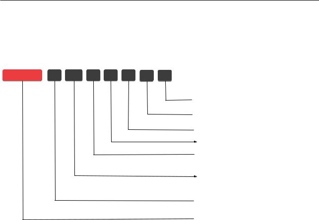
1.1Nomenclature
ESP32 |
D 0 WD R2 H Q6 V3 |
 &KLS UHYLVLRQ Y RU QHZHU
3DFNDJH
 Q6 4)1 1 $ 4)1
 +LJK WHPSHUDWXUH
,Q SDFNDJH PSRAM
R2: 2 MB PSRAM
 &RQQHFWLRQ
:' :L )L E J Q %OXHWRRWK %OXHWRRWK /( GXDO PRGH
,Q SDFNDJH flash
0 1R LQ SDFNDJH ƊDVK 2 0% ƊDVK0% ƊDVK
&RUH
 D/U 'XDO FRUH
S 6LQJOH FRUH
 &KLS 6HULHV
Figure 1-1. ESP32 Series Nomenclature
1.2Comparison
Table 1-1. ESP32 Series Comparison
|
|
|
In-Package |
|
VDD_SDIO |
|
Ordering code1 |
Core |
Chip Revision2 |
Flash/PSRAM |
Package |
Voltage |
|
ESP32-D0WD-V3 |
Dual core |
v3.0/v3.14 |
— |
QFN 5*5 |
1.8 V/3.3 V |
|
ESP32-D0WDR2-V3 |
Dual core |
v3.0/v3.14 |
2 |
MB PSRAM |
QFN 5*5 |
3.3 V |
ESP32-U4WDH |
Dual core3 |
v3.0/v3.14 |
4 |
MB flash (80 MHz) |
QFN 5*5 |
3.3 V |
ESP32-D0WDQ6-V3 (NRND) |
Dual core |
v3.0/v3.14 |
— |
QFN 6*6 |
1.8 V/3.3 V |
|
ESP32-D0WD (NRND) |
Dual core |
v1.0/v1.15 |
— |
QFN 5*5 |
1.8 V/3.3 V |
|
ESP32-D0WDQ6 (NRND) |
Dual core |
v1.0/v1.15 |
— |
QFN 6*6 |
1.8 V/3.3 V |
|
ESP32-S0WD (NRND) |
Single core |
v1.0/v1.15 |
— |
QFN 5*5 |
1.8 V/3.3 V |
|
1All above chips support Wi-Fi b/g/n + Bluetooth/Bluetooth LE Dual Mode connection. For details on chip marking and packing, see Section 5 Packaging.
2The differences between ESP32 chip revisions and the way to distinguish the revisions used in each chip are described in ESP32 Series SoC Errata.
3 ESP32-U4WDH will be produced as dual-core instead of single core. See PCN-2021-021 for more details.
4 The chips will be produced with chip revision v3.1 inside. See PCN20220901 for more details.
5 The chips will be produced with chip revision v1.1 inside. See PCN20220901 for more details.
Espressif Systems |
11 |
ESP32 Series Datasheet v4.3 |
Submit Documentation Feedback
