

1. From design unit, assembling unit and constructing unit:
1) Latest designing documents which have been modified during construction, 2) assembling and adjusting periodincluding drawings, presentation documents, processes documents, executing documents and monitoring log of designing unit
2)Acceptance reports of components
3)Acceptance reports of underground works
4) Manufacturer’s documents including processes, drawings, diagrams and other documents related with equipment
2.From testing unit
1)Test reports of automatic firefighting equipments
2)Test reports of surge arresters
3.From calibration unit
1)Reports of measurements
2)Reports of calibrations
3)Reports of principle diagrams test
4)Test reports of safety systems
5)Test reports of air ventilating systems
4.From testing and checking unit.
1)Testing and initial checking reports of the metal conduits
2)Testing and initial checking reports of main parts of generator In addition, Article 17 of this Guideline must be referred to.
Chapter 3 Personnel Preparation
Article 15. General requirements for personnel preparation
Personal preparation is required to be carried out for electric industry related enterprises and agencies
to arrange management and working staff properly for operation of power plant and power grid facilities. The required processes for personal preparation are as follows:
1. Education and experience requirements
Article 21 “Conditions for being granted electricity activity licenses”of Decree No.: 105/2005/NDCP “Decree on detailed regulations and guidelines on implementation of the electricity Law” (August 17, 2005) stipulate as follows:
1.Organizations, individuals engaged in electricity generation must satisfy the following criteria:
a)Possessing technology, equipment, auxiliary, workshop and constructions as approved design for construction, installation then being checked and accepted in accordance with existing technical standards;
12
b)Technical and production managers must have university degrees specialized in power sector or concerned qualification and worked at least five (05) years in power generation field.
c)The staffs that directly operate power generation must be trained and checked on operating procedures and safe procedures.
2.Units engaged in electricity transmission and distribution must satisfy the following criteria:
a)Possessing technology, equipment, auxiliary, workshop and constructions as approved design for construction, installation then being checked and accepted in accordance with existing technical standards, meeting requirements of maintenance, repair and check of transmission lines, transformers, switchgears, reactive power stations in power transmission and distribution network;
b)Technical managers must have university degrees specialized in power sector or concerned qualification and worked at least five (05) years in power transmission and distribution field;
2. Organizing and Auditing personal preparation
Leaders of electric companies, enterprises and agencies belong to electric industrymust organize and audit regularly the personnel preparation.
In the above connection, rules or programs of personal preparation andstaff training are required to be set up particularly for each power unit of power industry because the specific requirements of each power unit are different. These rules must meet the following basic criteria:
-Health condition must be suitable for profession and checked periodically.
-Staff must have basic knowledgesand/or experiences which are satisfactory with working requirements of assigned position.
-For staff of a specific position, it is required to have additional specific training and qualification of quality after the training.
Article 16. Knowledge test for personnel
Article 5.1.8 to Article 5.1.11 and Article 8.1 to Article 8.4 of QCVN 01 (2008)must be referred to regarding requirements of boiler tester. This regulation stipulates the requirements for health, training, checking, testing, certification, qualifications for the job titles related to boiler and pressure vessel, specifically the job titles of operating, repairing of boiler and pressure vessel, pressure welders.Staffs have been tested and certificatedwith occupational qualification and safety card in accordance with new job titles which are tasked with the operation and maintenance of boilers and pressure equipment.
Chapter 4 Plan for Repair of Equipment, Plant and Construction
Article 17. Keeping of necessary documents
Regarding the provisions of this article, reference shall be made to the documents listed in Article 50 of Part 4 for hydropower plant, Article 100 of Part 5 for thermal power plant and Article 249 of Part 6 for network facilities.
13
Article 18. Provision of related standards
Operation units of power plant and network facilities must prepare all of the standards and regulations related to inspection, repair, maintenance and operation of their facilities at least one set at each unit.
The documents to be prepared are, but not limited to, the following: 1. Hydro power
Number |
Issued |
|
|
|
|
|
Title |
|
|
|
|
|
|
|
|
|
|
|
|||||||||
TCVN1615-75 |
1975 |
Descriptor on Electric Diagram. Switchgear Equipments |
|
|
|||||||||
|
|
|
|
||||||||||
TCVN1987-1994 |
1994 |
Three phase asynchronous squirrel cage electrical motors from 0,55 |
|
||||||||||
to 90kW |
|
|
|
|
|
|
|
|
|
|
|
||
|
|
|
|
|
|
|
|
|
|
|
|
|
|
|
|
|
|
||||||||||
TCVN1988-77 |
1977 |
Electrical equipment for voltages up to 1000V. Enclosures. Degrees |
|
||||||||||
of protection. |
|
|
|
|
|
|
|
|
|
|
|||
|
|
|
|
|
|
|
|
|
|
|
|
||
|
|
|
|
|
|
|
|
||||||
TCVN2331-78 |
1978 |
Electrical |
rotary |
machines Determination |
of |
moment of inertia |
of |
||||||
rotary part. Test methods. |
|
|
|
|
|
|
|
|
|||||
|
|
|
|
|
|
|
|
|
|
||||
|
|
|
|
||||||||||
TCVN2280-78 |
1978 |
Three phase asynchronous electrical motors from 100W and higher |
|
||||||||||
power. Test methods. |
|
|
|
|
|
|
|
|
|
||||
|
|
|
|
|
|
|
|
|
|
|
|||
|
|
|
|
|
|
||||||||
TCVN2283-78 |
1978 |
Transformers for welding. General requirements. |
|
|
|
||||||||
|
|
|
|
||||||||||
TCVN3623-81 |
1981 |
Switching devices for voltages up to 1000V. General requirements. |
|
||||||||||
|
|
|
|
||||||||||
TCVN3662-81 |
1981 |
Metal-enclosed switchgear and control gear for voltages up to 10kV |
|
||||||||||
inclusive. Technical requirements |
|
|
|
|
|
|
|||||||
|
|
|
|
|
|
|
|
||||||
|
|
|
|
|
|||||||||
TCVN3682-81 |
1981 |
Rotating electrical machines. Types. Terms and Definitions |
|
|
|||||||||
|
|
|
|
|
|||||||||
TCVN3684-81 |
1981 |
Electrical equipment. Common concepts. Terms and Definitions |
|
|
|||||||||
|
|
|
|
|
|
|
|||||||
TCVN3685-81 |
1981 |
Cables wires and cords. Terms and Definitions |
|
|
|
|
|||||||
|
|
|
|
||||||||||
TCVN3689-82 |
1982 |
Electrical switch device. Common concepts. Terms and Definitions |
|
||||||||||
|
|
|
|
|
|||||||||
TCVN3725-82 |
1982 |
Electrical apparatus for voltages up to 1000V. Test methods. |
|
|
|||||||||
|
|
|
|
|
|
|
|
|
|||||
TCVN 3787-83 |
1983 |
Electrical relays. Terms and Definitions |
|
|
|
|
|
|
|||||
|
|
|
|
|
|||||||||
TCVN 3788-83 |
1983 |
Overhead line hardware. Basic concepts. Terms and Definitions |
|
|
|||||||||
|
|
|
|
|
|
|
|
||||||
TCVN 3816-83 |
1983 |
Electrical |
small |
motors |
for |
generalindustrial application. General |
|
||||||
requirements. |
|
|
|
|
|
|
|
|
|
|
|||
|
|
|
|
|
|
|
|
|
|
|
|
||
|
|
|
|
|
|
|
|
|
|
|
|||
TCVN 4160-90 |
1990 |
Electromagnetic |
Stators |
for |
voltages |
uo |
to |
1000V. |
G |
|
|||
requirements. |
|
|
|
|
|
|
|
|
|
|
|||
|
|
|
|
|
|
|
|
|
|
|
|
||
|
|
|
|
|
|
|
|
|
|
|
|
|
|
TCVN 4255:2008 |
2008 |
Degrees of protection provided by enclosures ( IP Code ) |
|
|
|||||||||
(IEC 60529:2001) |
|
|
|||||||||||
|
|
|
|
|
|
|
|
|
|
|
|
|
|
|
|
|
|
|
|
|
|
|
|
||||
TCVN 4306-86 |
1986 |
Electrical |
articles |
for |
tropical |
applications. |
General |
tec |
|
||||
specifications |
|
|
|
|
|
|
|
|
|
|
|||
|
|
|
|
|
|
|
|
|
|
|
|
||
|
|
|
|
|
|
|
|||||||
TCVN 4697-89 |
1989 |
Transformers nomenclature of quality indices |
|
|
|
|
|||||||
|
|
|
|
|
|
|
|
|
|
|
|
|
|
TCVN 4911:89 |
1989 |
Low – voltage electromagnetic contactors. Assembly sizes |
|
|
|||||||||
(ST SEV 1118-78) |
|
|
|||||||||||
|
|
|
|
|
|
|
|
|
|
|
|
|
|
|
|
|
|
|
|
|
|
|
|
||||
TCVN 4912-89 |
1989 |
Electrical |
apparatus |
for |
voltages up |
to |
1000V. |
Requirements |
|
||||
assembling sizes |
|
|
|
|
|
|
|
|
|
|
|||
|
|
|
|
|
|
|
|
|
|
|
|
||
|
|
|
|
|
|
|
|
|
|||||
TCVN 5064:1994 |
1994 |
Bare wires for overhead power lines |
|
|
|
|
|
|
|||||
|
|
|
|
|
|
|
|
|
|
|
|
|
|
14

Number |
Issued |
|
|
|
|
|
Title |
|
|
|
|
|
|
|
|
|
|
||
|
|
|
|
|
|
|
|
|
|
|
|
|
|
|
|
|
|
|
|
TCVN 5064:1994 / |
1994 |
Bare wires for overhead power lines |
|
|
|
|
|
|
|
|
|
|
|||||||
SD1: 1995) |
|
|
|
|
|
|
|
|
|
|
|||||||||
|
|
|
|
|
|
|
|
|
|
|
|
|
|
|
|
|
|
||
|
|
|
|
|
|
|
|
|
|
|
|||||||||
TCVN 5169:1993 |
1993 |
Porcelain through |
insulators of |
voltages |
of |
6 |
to |
|
35kV. Techn |
|
|||||||||
requirements |
|
|
|
|
|
|
|
|
|
|
|
|
|
|
|
||||
|
|
|
|
|
|
|
|
|
|
|
|
|
|
|
|
|
|||
|
|
|
|
|
|
|
|
|
|||||||||||
TCVN 5582:1991 |
1991 |
Cables, |
wires |
and |
cords. Determination |
of mechanical |
characteristic |
|
|||||||||||
of insulation and covering |
|
|
|
|
|
|
|
|
|
|
|
|
|||||||
|
|
|
|
|
|
|
|
|
|
|
|
|
|
||||||
|
|
|
|
|
|
|
|
|
|
|
|
|
|||||||
TCVN 5768:1993 |
1993 |
Switches for voltages above 1000V |
|
|
|
|
|
|
|
|
|
|
|||||||
|
|
|
|
|
|
|
|
|
|||||||||||
TCVN 5844:1994 |
1994 |
Power |
electric cables |
with voltage up |
to |
35kV. General |
techni |
|
|||||||||||
requirements |
|
|
|
|
|
|
|
|
|
|
|
|
|
|
|
||||
|
|
|
|
|
|
|
|
|
|
|
|
|
|
|
|
|
|||
|
|
|
|
||||||||||||||||
TCVN 5926-3:2007 |
2007 |
Low – voltage fuses – Part 3: Supplementary requirements for fuses for |
|
||||||||||||||||
use by |
unskilled |
persons |
( fuses mainly |
for |
household |
and |
|
similar |
|||||||||||
(IEC 60529:2001) |
|
||||||||||||||||||
|
applications ) |
|
|
|
|
|
|
|
|
|
|
|
|
|
|
|
|||
|
|
|
|
|
|
|
|
|
|
|
|
|
|
|
|
|
|||
|
|
|
|
||||||||||||||||
TCVN 5935-1995 |
1995 |
Extruded solid dielectric insulated power cables for rated voltages from |
|
||||||||||||||||
(IEC 502-1983) |
1kV up to 30kV |
|
|
|
|
|
|
|
|
|
|
|
|
|
|
||||
|
|
|
|
|
|
|
|
|
|
|
|
|
|
|
|||||
|
|
|
|
|
|
|
|
|
|
||||||||||
TCVN 5936-1:1995 |
1995 |
Test methods |
for insulations and |
sheaths |
of |
electric |
cables |
and cords |
|||||||||||
(IEC 540:1982) |
( Elastomeric and thermoplastic compounds |
|
|
|
|
|
|
|
|
|
|||||||||
|
|
|
|
|
|
|
|
|
|
||||||||||
|
|
|
|
|
|
|
|
|
|
|
|||||||||
TCVN 6099-1:2007 |
2007 |
High-voltage |
test |
techniques. |
Part |
1: |
general |
definition |
an |
||||||||||
(IEC 60060-1:1989) |
requirements |
|
|
|
|
|
|
|
|
|
|
|
|
|
|
|
|||
|
|
|
|
|
|
|
|
|
|
|
|
|
|
|
|
||||
|
|
|
|
|
|
|
|
|
|
|
|
|
|
|
|
|
|
|
|
TCVN 6099-2:2007 |
2007 |
High-voltage test techniques. Part 2: measuring systems |
|
|
|
|
|
||||||||||||
(IEC 60060-2:1994) |
|
|
|
|
|
||||||||||||||
|
|
|
|
|
|
|
|
|
|
|
|
|
|
|
|
|
|
||
|
|
|
|
|
|
|
|
|
|||||||||||
TCVN 6099-3:2007 |
2007 |
High-voltage |
test techniques. Part |
3: definitions |
and |
requirements |
for |
||||||||||||
(IEC 60060-3:2006) |
on-site testing |
|
|
|
|
|
|
|
|
|
|
|
|
|
|
|
|||
|
|
|
|
|
|
|
|
|
|
|
|
|
|
|
|
||||
|
|
|
|
|
|
|
|
|
|
|
|
|
|
|
|
|
|
|
|
TCVN 6306-1:2006 |
2006 |
Power transformers. Part 1: general |
|
|
|
|
|
|
|
|
|
|
|
||||||
(IEC 60076-1:2000) |
|
|
|
|
|
|
|
|
|
|
|
||||||||
|
|
|
|
|
|
|
|
|
|
|
|
|
|
|
|
|
|
||
|
|
|
|
|
|
|
|
|
|
|
|
|
|
|
|
|
|
|
|
TCVN 6306-2:2006 |
2006 |
Power transformers. Part 2: temperature rise |
|
|
|
|
|
|
|
|
|
||||||||
(IEC 60076-2:1993) |
|
|
|
|
|
|
|
|
|
||||||||||
|
|
|
|
|
|
|
|
|
|
|
|
|
|
|
|
|
|
||
|
|
|
|
|
|
|
|
|
|
||||||||||
TCVN 6306-3:2006 |
2006 |
Power |
transformers. |
Part3: insulation |
levels, |
|
dielectric tests, |
a |
|||||||||||
(IEC 60076-3:2000) |
external clearances in air |
|
|
|
|
|
|
|
|
|
|
|
|
||||||
|
|
|
|
|
|
|
|
|
|
|
|
|
|||||||
|
|
|
|
|
|
|
|
|
|
|
|
|
|
|
|
|
|
|
|
TCVN 6306-5:2006 |
2006 |
Power transformers. Part 5: ability to withstand short circuit |
|
|
|
||||||||||||||
(IEC 60076-5:2006) |
|
|
|
||||||||||||||||
|
|
|
|
|
|
|
|
|
|
|
|
|
|
|
|
|
|
||
|
|
|
|
|
|
|
|
|
|
|
|
|
|
|
|
|
|
|
|
TCVN 6306-11:2009 |
2009 |
Power transformers. Part 11: dry-type transformers |
|
|
|
|
|
|
|
||||||||||
(IEC 60076-11:2004) |
|
|
|
|
|
|
|
||||||||||||
|
|
|
|
|
|
|
|
|
|
|
|
|
|
|
|
|
|
||
|
|
|
|
||||||||||||||||
TCVN 6434-1:2008 |
2008 |
Electrical accessories – Circuit-breakers for overcurrent protection for |
|||||||||||||||||
household and similar |
installations– Part |
1: circuitbreakers- |
for a.c. |
||||||||||||||||
(IEC 60898-1:2003) |
|||||||||||||||||||
|
operation |
|
|
|
|
|
|
|
|
|
|
|
|
|
|
|
|||
|
|
|
|
|
|
|
|
|
|
|
|
|
|
|
|
|
|||
|
|
|
|
|
|
|
|
|
|
||||||||||
TCVN 6447:1998 |
1998 |
Electric |
cables – |
XLPE |
insulated – Aerial |
bundled |
for |
workin |
|||||||||||
voltages up to 0,6/1kV |
|
|
|
|
|
|
|
|
|
|
|
|
|
||||||
|
|
|
|
|
|
|
|
|
|
|
|
|
|
|
|||||
|
|
|
|
|
|
|
|
|
|
|
|
|
|
|
|
|
|
|
|
TCVN 6592-1:2001 |
2001 |
Low – voltage switchgear and controlgear – Part 1: general rules |
|
|
|
||||||||||||||
(IEC 60947-1:1999) |
|
|
|
||||||||||||||||
|
|
|
|
|
|
|
|
|
|
|
|
|
|
|
|
|
|
||
|
|
|
|
|
|
|
|
|
|
|
|
|
|
|
|
|
|
|
|
TCVN 6592-2:2000 |
2000 |
Low – voltage switchgear and controlgear – Part 2: circuit-breakers |
|
|
|||||||||||||||
(IEC 947-2:1995) |
|
|
|||||||||||||||||
|
|
|
|
|
|
|
|
|
|
|
|
|
|
|
|
|
|
||
|
|
|
|
|
|
|
|
|
|
|
|
|
|
|
|
|
|
|
|
15

Number |
Issued |
|
|
Title |
|
|
|
|
|
|
|
|
|||
|
|
|
|
|
|
|
|||||||||
TCVN 6592-4-1:2001 |
|
Low – voltage switchgear and |
controlgear– Part 4: Contactors |
and |
|
||||||||||
2001 |
motor-starters. Section one: electromechanical |
contactors |
and |
motor- |
|
||||||||||
(IEC 6592-4-1:1990) |
|
||||||||||||||
|
starters |
|
|
|
|
|
|
|
|
|
|
|
|||
|
|
|
|
|
|
|
|
|
|
|
|
|
|
||
|
|
|
|
|
|
|
|
|
|
|
|
||||
TCVN 6610-1:2007 |
|
Polyvinyl |
chloride |
insulated |
cables |
of |
rated |
voltages |
up |
|
|||||
2007 |
including 450/750V |
|
|
|
|
|
|
|
|
|
|
||||
(IEC 60227-1:1998) |
|
|
|
|
|
|
|
|
|
|
|||||
|
- Part 1: General requirements. |
|
|
|
|
|
|
|
|
|
|||||
|
|
|
|
|
|
|
|
|
|
|
|
||||
|
|
|
|
|
|
|
|
|
|
|
|
||||
TCVN 6610-2:2007 |
|
Polyvinyl |
chloride |
insulated |
cables |
of |
rated |
voltages |
up |
|
|||||
2007 |
including 450/750V |
|
|
|
|
|
|
|
|
|
|
||||
(IEC 60227-2:2003) |
|
|
|
|
|
|
|
|
|
|
|||||
|
- Part 2: Test methods. |
|
|
|
|
|
|
|
|
|
|||||
|
|
|
|
|
|
|
|
|
|
|
|
||||
|
|
|
|
|
|
|
|
|
|
|
|
||||
TCVN 6610-3:2007 |
|
Polyvinyl |
chloride |
insulated |
cables |
of |
rated |
voltages |
up |
|
|||||
2007 |
including 450/750V |
|
|
|
|
|
|
|
|
|
|
||||
(IEC 227-3:1997) |
|
|
|
|
|
|
|
|
|
|
|||||
|
- Part 3: Non-sheathed cables for fixed wiring |
|
|
|
|
|
|
||||||||
|
|
|
|
|
|
|
|
|
|||||||
|
|
|
|
|
|
|
|
|
|
|
|
||||
TCVN 6610-4:2007 |
|
Polyvinyl |
chloride |
insulated |
cables |
of |
rated |
voltages |
up |
|
|||||
2007 |
including 450/750V |
|
|
|
|
|
|
|
|
|
|
||||
(IEC 227-4:1992) |
|
|
|
|
|
|
|
|
|
|
|||||
|
- Part 4: sheathed cables for fixed wiring |
|
|
|
|
|
|
|
|||||||
|
|
|
|
|
|
|
|
|
|
||||||
|
|
|
|
|
|
|
|
|
|
|
|
||||
TCVN 6610-5:2007 |
|
Polyvinyl |
chloride |
insulated |
cables |
of |
rated |
voltages |
up |
|
|||||
2007 |
including |
|
|
450/750V |
|
|
|
|
- |
|
|||||
(IEC 60227-5:2003) |
|
|
|
|
|
|
|
||||||||
|
Part 5: flexible cables ( cords) |
|
|
|
|
|
|
|
|
|
|||||
|
|
|
|
|
|
|
|
|
|
|
|
||||
|
|
|
|
|
|
|
|
|
|
|
|
||||
TCVN 6610-6:2000 |
|
Polyvinyl |
chloride |
insulated |
cables |
of |
rated |
voltages |
up |
|
|||||
2000 |
including |
|
|
450/750V |
|
|
|
|
- |
|
|||||
(IEC 227-6:1985) |
|
|
|
|
|
|
|
||||||||
|
Part 6: lift cables and cables for flexible connections |
|
|
|
|
|
|||||||||
|
|
|
|
|
|
|
|
||||||||
|
|
|
|
|
|||||||||||
TCVN |
6613-1:2000 |
2000 |
Tests on electric cables under fire conditions– Part 1: Test on a single |
|
|||||||||||
(IEC 332-1:1993) |
vertical insulated wire or cables |
|
|
|
|
|
|
|
|
|
|||||
|
|
|
|
|
|
|
|
|
|
||||||
TCVN 6614-1-2:2008 |
|
Common test methods for insulating and sheathing materials of electric |
|
||||||||||||
(IEC60811-1-2:1985) |
2008 |
cables and optical cables – Part 1-2: methods for general application– |
|
||||||||||||
|
|
|
thermal ageing methods |
|
|
|
|
|
|
|
|
|
|||
|
|
|
|
|
|
|
|
|
|
|
|
|
|
||
TCVN 6615-1:2000 |
2000 |
Switches for appliances – Part 1: General requirements. |
|
|
|
|
|
||||||||
(IEC 1058-1:1996) |
|
|
|
|
|
||||||||||
|
|
|
|
|
|
|
|
|
|
|
|
|
|||
|
|
|
|
|
|
|
|
|
|
|
|
|
|
||
TCVN 6627-1:2008 |
2008 |
Rotating electrical machines – Part 1: Rating and performance |
|
|
|
||||||||||
(IEC 60034-1:2004) |
|
|
|
||||||||||||
|
|
|
|
|
|
|
|
|
|
|
|
|
|||
|
|
|
|
|
|||||||||||
TCVN 6627-2:2001 |
|
Rotating electrical machines – Part 2: methods for determining losses |
|
||||||||||||
2001 |
and efficiency of rotating electrical |
machinery from |
tests |
( excluding |
|
||||||||||
(IEC 34-2:1972) |
|
||||||||||||||
|
machines for traction vehicles) |
|
|
|
|
|
|
|
|
|
|||||
|
|
|
|
|
|
|
|
|
|
|
|
||||
|
|
|
|
|
|||||||||||
|
|
|
Rotating electrical machines – Part 2: methods for determining losses |
|
|||||||||||
TCVN 6627-2A:2001 |
2001 |
and efficiency of rotating electrical |
machinery from |
tests |
( excluding |
|
|||||||||
(IEC 34-2A:1974) |
machines for traction vehicles)easurement of |
losses |
by |
|
|||||||||||
|
|
||||||||||||||
|
|
|
calorimetric method |
|
|
|
|
|
|
|
|
|
|
||
|
|
|
|
|
|
|
|
|
|
||||||
TCVN 6627-3:2000 |
2000 |
Rotating |
electrical |
machines– |
Part |
3: |
Specific |
requirements |
|
||||||
(IEC 34-3:1988) |
turbine-type synchronous machines |
|
|
|
|
|
|
|
|
||||||
|
|
|
|
|
|
|
|
|
|||||||
|
|
|
|
|
|||||||||||
TCVN |
6627-5:2008 |
|
Rotating electrical machines – Part 5: Degrees of protection provided |
|
|||||||||||
2008 |
by the integral design of rotating |
Electrical machines |
( |
IP |
code)– |
||||||||||
(IEC 60034-5:2000) |
|||||||||||||||
|
Classification |
|
|
|
|
|
|
|
|
|
|
||||
|
|
|
|
|
|
|
|
|
|
|
|
|
|||
|
|
|
|
|
|
|
|
|
|
|
|
||||
TCVN 6627-7:2008 |
|
Rotating |
electrical |
machines– |
Part |
7: |
Classificationof |
types |
o |
||||||
2008 |
construction, mounting arrangements |
and |
terminal box position |
( IM |
|||||||||||
(IEC 60034-7:2001) |
|||||||||||||||
|
code) |
|
|
|
|
|
|
|
|
|
|
|
|||
|
|
|
|
|
|
|
|
|
|
|
|
|
|
||
|
|
|
|
|
|
|
|
|
|
|
|
|
|
|
|
16

Number |
Issued |
|
|
|
|
|
Title |
|
|
|
|
|
|
||
|
|
|
|
||||||||||||
TCVN 6627-8:2000 |
2000 |
Rotating electrical machines – Part 8: Terminal markings and direction |
|
||||||||||||
(IEC 34-8:1972) |
of rotation of rotating machines |
|
|
|
|
|
|
|
|||||||
|
|
|
|
|
|
|
|
||||||||
|
|
|
|
|
|
|
|
|
|
|
|
|
|
|
|
TCVN 6627-9:2000 |
2000 |
Rotating electrical machines – Part 9: noise limits |
|
|
|
|
|||||||||
(IEC 34-9:1990) |
|
|
|
|
|||||||||||
|
|
|
|
|
|
|
|
|
|
|
|
|
|
||
|
|
|
|
|
|
|
|
|
|
|
|
|
|
|
|
TCVN 6627-11:2008 |
2008 |
Rotating electrical machines – Part 11: Thermal protection |
|
|
|
||||||||||
(IEC 60034-11:2004) |
|
|
|
||||||||||||
|
|
|
|
|
|
|
|
|
|
|
|
|
|
||
|
|
|
|
||||||||||||
TCVN 6627-14:2008 |
|
Rotating electrical machines – Part 14: mechanical vibration of certain |
|
||||||||||||
2008 |
machines |
with |
shaft |
heights |
56mm |
and-measurement,higher |
|
||||||||
(IEC 60034-14:2003) |
|
||||||||||||||
|
evaluation and limits of vibration severity |
|
|
|
|
|
|||||||||
|
|
|
|
|
|
|
|||||||||
|
|
|
|
|
|
|
|
||||||||
TCVN 7540-1:2005 |
2005 |
High efficiency three-phase |
asynchronous |
squirrel |
cage |
Electrical |
|
||||||||
motors |
|
|
|
|
|
|
|
|
|
– |
|
||||
|
|
Part 1: minimum energy performance |
|
|
|
|
|
|
|||||||
|
|
|
|
|
|
|
|
||||||||
|
|
High efficiency three-phase |
asynchronous |
squirrel |
cage |
Electri |
|
||||||||
TCVN 7540-2:2005 |
2005 |
motors |
|
|
|
|
|
|
|
|
|
– |
|
||
|
|
Part 2: methods for determination of energy performance |
|
|
|
||||||||||
|
|
|
|
|
|
|
|
|
|
|
|
|
|
|
|
TCVN 7697-1:2007 |
2007 |
Instrument transformers – Part 1: current transformers |
|
|
|
||||||||||
(IEC 60044-1:2003) |
|
|
|
||||||||||||
|
|
|
|
|
|
|
|
|
|
|
|
|
|
||
|
|
|
|
|
|
|
|
|
|
|
|
|
|
|
|
TCVN 7697-2:2007 |
2007 |
Instrument transformers – Part 2: Inductive voltage transformers |
|
|
|||||||||||
(IEC 60044-2:2003) |
|
|
|||||||||||||
|
|
|
|
|
|
|
|
|
|
|
|
|
|
||
|
|
|
|
|
|
|
|
|
|
|
|
|
|
|
|
TCVN 7883-8:2008 |
2008 |
Electrical relays – Part 8: thermal electrical relays |
|
|
|
||||||||||
(IEC 60255-8:1990) |
|
|
|
||||||||||||
|
|
|
|
|
|
|
|
|
|
|
|
|
|
||
|
|
|
|
|
|
|
|
|
|
|
|||||
TCVN 7994-1:2009 |
2009 |
Low |
– |
voltage |
switchgear |
|
and |
controlgear |
assemblies– |
||||||
(IEC 60439-1:2004) |
Part 1: Type-tested and partially type-tested assemblies |
|
|
|
|||||||||||
|
|
|
|
||||||||||||
|
|
|
|
|
|
|
|
|
|
|
|
|
|
|
|
TCVN 7995:2009 |
2009 |
Standard voltages |
|
|
|
|
|
|
|
|
|
|
|||
(IEC 60038:2002): |
|
|
|
|
|
|
|
|
|
|
|||||
|
|
|
|
|
|
|
|
|
|
|
|
|
|
||
|
|
|
|
|
|
|
|||||||||
TCVN 7997:2009 |
2009 |
Power cables buried ground – installation method |
|
|
|
|
|||||||||
|
|
|
|
|
|
|
|
|
|
|
|
|
|||
TCVN 7998-1:2009 |
|
Insulators |
for overhead |
lines |
with |
a |
nominal |
|
voltage |
above |
1000V– |
||||
2009 |
Part |
1: ceramic or glass |
insulator |
units for a.csystems. – Definitions, |
|||||||||||
(IEC 60383-1:1993) |
|||||||||||||||
|
test methods and acceptance criteria |
|
|
|
|
|
|
|
|||||||
|
|
|
|
|
|
|
|
|
|||||||
|
|
|
|
|
|
|
|
|
|
|
|
|
|||
TCVN 7998-2:2009 |
|
Insulators |
for overhead |
lines |
with |
a |
nominal |
|
voltage |
above |
1000V– |
||||
2009 |
Part |
2: |
insulator |
strings |
and |
insulator |
sets |
forsystemsa.c. – |
|||||||
(IEC 60383-2:1993) |
|||||||||||||||
|
Definitions, test methods and acceptance criteria |
|
|
|
|
|
|||||||||
|
|
|
|
|
|
|
|||||||||
|
|
|
|
|
|
|
|
|
|
|
|
|
|
|
|
TCVN 7999-1:2009 |
2009 |
High – voltage fuses – Part 1: current-limiting fuses |
|
|
|
||||||||||
(IEC 60282-1:2005) |
|
|
|
||||||||||||
|
|
|
|
|
|
|
|
|
|
|
|
|
|
||
|
|
|
|
|
|
|
|
|
|
|
|
|
|
|
|
TCVN 7999-2:2009 |
2009 |
High–voltage fuses – Part 2: expulsion fuses |
|
|
|
|
|
||||||||
(IEC 60282-2:2008) |
|
|
|
|
|
||||||||||
|
|
|
|
|
|
|
|
|
|
|
|
|
|
||
|
|
|
|
|
|
|
|
|
|
|
|
|
|
|
|
National Codes for |
2006 |
General Requirements |
|
|
|
|
|
|
|
|
|
|
|||
Electrical Facilities |
|
|
|
|
|
|
|
|
|
|
|||||
|
|
|
|
|
|
|
|
|
|
|
|
|
|
||
|
|
|
|
|
|
|
|
|
|
|
|
|
|
|
|
National Codes for |
2006 |
Transmission Power System |
|
|
|
|
|
|
|
|
|||||
Electrical Facilities |
|
|
|
|
|
|
|
|
|||||||
|
|
|
|
|
|
|
|
|
|
|
|
|
|
||
|
|
|
|
|
|
|
|
|
|
|
|
|
|
|
|
National Codes for |
2006 |
Distribution Equipments and Electrical Substation Facilities |
|
|
|||||||||||
Electrical Facilities |
|
|
|||||||||||||
|
|
|
|
|
|
|
|
|
|
|
|
|
|
||
|
|
|
|
|
|
|
|
|
|
|
|
|
|
|
|
National Codes for |
2006 |
Protection and Automation |
|
|
|
|
|
|
|
|
|||||
Electrical Facilities |
|
|
|
|
|
|
|
|
|||||||
|
|
|
|
|
|
|
|
|
|
|
|
|
|
||
|
|
|
|
|
|
|
|
|
|
|
|
|
|
|
|
National Codes for |
2008 |
Electrical Facilities Calibration |
|
|
|
|
|
|
|
|
|||||
Electrical Technics |
|
|
|
|
|
|
|
|
|||||||
|
|
|
|
|
|
|
|
|
|
|
|
|
|
||
|
|
|
|
|
|
|
|
|
|
|
|
|
|
|
|
17
|
Number |
Issued |
|
|
|
|
|
Title |
|
|
|
|
|
|
|
|
|
|
|
|
|
|
|
|
|
|
|
|
|
|
|
|
|
National Codes for |
2008 |
Operating and Maintenance of Power System Facilities |
|
|
|
|
|
|||||||||
Electrical Technics |
|
|
|
|
|
|||||||||||
|
|
|
|
|
|
|
|
|
|
|
|
|
|
|
||
|
|
|
|
|
|
|
|
|
|
|
|
|
|
|
|
|
National Codes for |
2008 |
Installation Power Network |
|
|
|
|
|
|
|
|
|
|
||||
Electrical Technics |
|
|
|
|
|
|
|
|
|
|
||||||
|
|
|
|
|
|
|
|
|
|
|
|
|
|
|
||
|
|
|
|
|
|
|
|
|
|
|
|
|
|
|
|
|
National Codes for |
2008 |
National Technical regulation on Electric Safety |
|
|
|
|
|
|
||||||||
Electrical Technics |
|
|
|
|
|
|
||||||||||
|
|
|
|
|
|
|
|
|
|
|
|
|
|
|
||
|
|
|
|
|
|
|
|
|
|
|
|
|
|
|
|
|
2. Thermal power |
|
|
|
|
|
|
|
|
|
|
|
|
|
|
|
|
(1) |
Mechanical |
|
|
|
|
|
|
|
|
|
|
|
|
|
|
|
|
|
|
|
|
|
|
|
|
|
|
|
|
|
|
|
|
|
Number |
Issued |
|
|
|
|
|
Title |
|
|
|
|
|
|
|
|
|
|
|
|
|
|
|
|
|
|
|
||||||
|
TCVN3949 |
1984 |
Coal for |
pulverized |
coal |
burning |
boilers |
inr |
powestations. |
|
||||||
|
Specifications |
|
|
|
|
|
|
|
|
|
|
|
||||
|
|
|
|
|
|
|
|
|
|
|
|
|
|
|||
|
|
|
|
|
|
|
|
|||||||||
|
TCVN4395 |
1986 |
Non-destructive testing. |
Radiographic testing |
of welded |
joints |
|
|||||||||
|
metallic materials using X and gamma-rays |
|
|
|
|
|
|
|
||||||||
|
|
|
|
|
|
|
|
|
|
|||||||
|
|
|
|
|
|
|
|
|
|
|||||||
|
TCVN5400 |
1991 |
Welded |
joints. General |
requirements of |
sampling |
for |
mechani |
|
|||||||
|
test |
|
|
|
|
|
|
|
|
|
|
|
|
|
||
|
|
|
|
|
|
|
|
|
|
|
|
|
|
|
|
|
|
|
|
|
|
|
|
|
|
|
|
|
|||||
|
TCVN5401 |
1991 |
Welded joints. Bending test method |
|
|
|
|
|
|
|
|
|||||
|
|
|
|
|
|
|
|
|||||||||
|
TCVN5401 |
2010 |
Destructive tests on welds in metallic materials. Bend tests |
|
|
|
|
|||||||||
|
|
|
|
|
|
|
|
|
|
|
||||||
|
TCVN5402 |
1991 |
Welded joints. Blow-bending test method |
|
|
|
|
|
|
|
||||||
|
|
|
|
|
|
|
|
|||||||||
|
TCVN5402 |
2010 |
Destructive |
tests on |
welds in metallic materials. Impact |
test. Test |
||||||||||
|
specimen location, notch orientation and examination |
|
|
|
|
|
||||||||||
|
|
|
|
|
|
|
|
|||||||||
|
TCVN6008 |
2010 |
Pressure |
equipment. |
Welded. |
Technical |
requirements |
and |
testi |
|||||||
|
methods |
|
|
|
|
|
|
|
|
|
|
|
|
|
||
|
|
|
|
|
|
|
|
|
|
|
|
|
|
|
|
|
|
|
|
|
|
|
|
||||||||||
|
|
|
Pressure |
|
vessels. Safety engineering requirements of |
|||||||||||
|
TCVN6154 |
1996 |
construction, manufacture. Testing methods |
|
|
|
|
|
|
|
||||||
|
|
|
|
|
|
|
|
|||||||||
|
TCVN6155 |
1996 |
Pressure |
vessels. Safety engineering |
requirements of erection, |
use, |
||||||||||
|
repair |
|
|
|
|
|
|
|
|
|
|
|
|
|
||
|
|
|
|
|
|
|
|
|
|
|
|
|
|
|
|
|
|
|
|
|
|
|
|
|
|||||||||
|
TCVN6156 |
1996 |
Pressure |
vessels. Safety engineering |
requirements of erection, |
use, |
||||||||||
|
repair. Testing method |
|
|
|
|
|
|
|
|
|
|
|
||||
|
|
|
|
|
|
|
|
|
|
|
|
|
|
|||
|
|
|
|
|
|
|
|
|
|
|||||||
|
TCVN6159 |
1996 |
Pipe lines for vapor and hot water. Test methods |
|
|
|
|
|
|
|||||||
|
|
|
|
|
||||||||||||
|
|
|
Gas cylinders. Cylinders for permanent gases. Inspection at time of |
|||||||||||||
|
TCVN6290 |
1997 |
filling |
|
|
|
|
|
|
|
|
|
|
|
|
|
|
|
|
|
|
|
|
|
|
|
|
|
|||||
|
TCVN 7704 |
2007 |
Boilers. |
|
Technical |
requirement |
of |
|
design, |
c |
||||||
|
manufacture, installation, operation, maintenance |
|
|
|
|
|
|
|||||||||
|
|
|
|
|
|
|
|
|
||||||||
|
|
|
|
|
|
|
|
|
|
|
|
|
|
|
|
|
(2) |
Electrical |
|
|
|
|
|
|
|
|
|
|
|
|
|
|
|
|
|
|
|
|
|
|
|
|
|
|
|
|
|
|
|
|
|
Number |
Issued |
|
|
|
|
|
Title |
|
|
|
|
|
|
|
|
|
|
|
|
|
|
|
|
|
|
|
|
|||||
|
TCVN 1615 |
1975 |
Graphical |
symbols |
to |
be |
used |
electrical |
diagrams. |
Switch |
|
|||||
|
equipments |
|
|
|
|
|
|
|
|
|
|
|
||||
|
|
|
|
|
|
|
|
|
|
|
|
|
|
|||
|
|
|
|
|
|
|
|
|
|
|
|
|
|
|
|
|
18
Number |
Issued |
|
|
|
|
|
|
Title |
|
|
|
|
|
|
|
|
|
||
|
|
|
|||||||||||||||||
TCVN 1978 |
1994 |
Three-phase asynchronous squirrel cage motors of powers from |
|||||||||||||||||
0,55 to 90 kW |
|
|
|
|
|
|
|
|
|
|
|
|
|
|
|
||||
|
|
|
|
|
|
|
|
|
|
|
|
|
|
|
|
|
|||
|
|
|
|
|
|
|
|
||||||||||||
TCVN 3662 |
1981 |
Metalenclosed switchgear and |
controlgear |
for |
voltages |
up |
to |
||||||||||||
10 kV inclusive. Specifications |
|
|
|
|
|
|
|
|
|
|
|
||||||||
|
|
|
|
|
|
|
|
|
|
|
|
|
|||||||
|
|
|
|
|
|
|
|
|
|
|
|||||||||
TCVN 3715 |
1982 |
Enclosed |
transformer |
stations |
of |
powers |
up |
to |
1000 |
kVA |
|||||||||
voltages up to 20 kV inclusive. General specifications |
|
|
|
||||||||||||||||
|
|
|
|
|
|||||||||||||||
|
|
|
|
|
|||||||||||||||
TCVN 3725 |
1982 |
Electrical apparatus for voltages up to 1000 V. Test methods |
|
|
|||||||||||||||
|
|
|
|
|
|
|
|
||||||||||||
TCVN 4696 |
1989 |
Low-voltage |
electrical |
equipments. |
|
Requirements |
for |
||||||||||||
electrical insulation |
|
|
|
|
|
|
|
|
|
|
|
|
|
||||||
|
|
|
|
|
|
|
|
|
|
|
|
|
|
|
|||||
|
|
|
|
|
|
|
|
|
|||||||||||
TCVN 4757 |
1989 |
Synchronous |
three-phase generators |
of |
powers |
above |
110 |
kW |
|||||||||||
General specifications |
|
|
|
|
|
|
|
|
|
|
|
|
|
||||||
|
|
|
|
|
|
|
|
|
|
|
|
|
|
|
|||||
|
|
|
|
|
|
|
|
|
|
|
|||||||||
TCVN 4758 |
1989 |
Synchronous |
generators |
of |
powers |
up |
to |
110 |
kW. |
G |
|||||||||
specifications |
|
|
|
|
|
|
|
|
|
|
|
|
|
|
|
||||
|
|
|
|
|
|
|
|
|
|
|
|
|
|
|
|
|
|||
|
|
|
|
|
|
|
|
|
|
|
|
|
|
||||||
TCVN 4762 |
1989 |
Power cables. Nominal voltages |
|
|
|
|
|
|
|
|
|
|
|
||||||
|
|
|
|
|
|
|
|
||||||||||||
TCVN 5169 |
1993 |
Porcelain through |
insulators for |
voltages |
from 10 |
(6) to |
35 k |
||||||||||||
Technical requirements |
|
|
|
|
|
|
|
|
|
|
|
|
|
||||||
|
|
|
|
|
|
|
|
|
|
|
|
|
|
|
|||||
|
|
|
|
|
|
|
|
|
|
|
|||||||||
TCVN 5170 |
1990 |
Porcelain |
through |
insulators |
|
for |
|
voltages |
up |
to |
|||||||||
Acceptance rules and test methods |
|
|
|
|
|
|
|
|
|
|
|||||||||
|
|
|
|
|
|
|
|
|
|
|
|
||||||||
|
|
|
|
|
|||||||||||||||
TCVN 5427 |
1991 |
Power transformers. Top-changing devices. Specifications |
|
|
|||||||||||||||
|
|
|
|
|
|
|
|
|
|
||||||||||
TCVN 5428 |
1991 |
Power |
transformers. |
Methods |
|
of |
measuring |
partial |
discha |
||||||||||
intensiveness during AC voltage testing |
|
|
|
|
|
|
|
|
|||||||||||
|
|
|
|
|
|
|
|
|
|
||||||||||
|
|
|
|
|
|
|
|
|
|||||||||||
TCVN 5429 |
1991 |
Power |
transformers |
and |
reactors. |
Requirements |
for |
ele |
|||||||||||
insulation strength |
|
|
|
|
|
|
|
|
|
|
|
|
|
|
|||||
|
|
|
|
|
|
|
|
|
|
|
|
|
|
|
|
||||
|
|
|
|
|
|
|
|
||||||||||||
TCVN 5430 |
1991 |
Power |
transformers. Test |
methods |
of |
inside electric |
insulati |
||||||||||||
strength by switching impulse |
|
|
|
|
|
|
|
|
|
|
|
||||||||
|
|
|
|
|
|
|
|
|
|
|
|
|
|||||||
|
|
|
|
||||||||||||||||
TCVN 5431 |
1991 |
Oil power transformers for general purpose. Permissible loads |
|
||||||||||||||||
|
|
|
|
|
|
|
|
|
|
||||||||||
TCVN 5432 |
1991 |
Power |
|
transformers. |
Test |
methods |
lectricof |
strength |
o |
||||||||||
insulation by A.C voltages at industrial frequency |
|
|
|
|
|
||||||||||||||
|
|
|
|
|
|
|
|||||||||||||
|
|
|
|
|
|
|
|||||||||||||
TCVN 5433 |
1991 |
Power transformers. Methods of short-circuit testing |
|
|
|
|
|||||||||||||
|
|
|
|
|
|
|
|
|
|||||||||||
TCVN 5434 |
1991 |
Power transformers. Test method of heating |
|
|
|
|
|
|
|||||||||||
|
|
|
|
|
|
|
|
|
|
|
|
||||||||
TCVN 5435 |
1991 |
Power |
|
transformers. |
Methods |
|
for |
|
measuring |
|
dielectri |
||||||||
parameters of insulation |
|
|
|
|
|
|
|
|
|
|
|
|
|||||||
|
|
|
|
|
|
|
|
|
|
|
|
|
|
||||||
|
|
|
|
|
|
|
|
|
|
|
|||||||||
TCVN 5844 |
1994 |
Power |
electric |
cables |
with |
voltages |
up |
to |
35kV. |
|
|||||||||
technical requirements |
|
|
|
|
|
|
|
|
|
|
|
|
|
||||||
|
|
|
|
|
|
|
|
|
|
|
|
|
|
|
|||||
|
|
|
|
|
|
|
|
|
|
|
|
|
|
|
|
||||
TCVN 5928 |
1995 |
Current transformers |
|
|
|
|
|
|
|
|
|
|
|
|
|
||||
|
|
|
|
|
|
|
|
|
|
||||||||||
TCVN 6036-3-1 |
1997 |
Power |
transformers. |
Part |
3/1: |
Insulation |
levels |
and |
dielec |
||||||||||
tests. External clearances in air |
|
|
|
|
|
|
|
|
|
|
|
||||||||
|
|
|
|
|
|
|
|
|
|
|
|
|
|||||||
|
|
|
|
|
|
|
|
|
|
|
|
|
|
|
|
||||
TCVN 6097 |
1996 |
Voltage transformers |
|
|
|
|
|
|
|
|
|
|
|
|
|
||||
|
|
|
|
|
|
|
|
|
|
|
|
||||||||
TCVN 6306-1 |
2001 |
Power transformers. Part 1: General |
|
|
|
|
|
|
|
|
|
||||||||
|
|
|
|
|
|
|
|
|
|||||||||||
TCVN 6306-2 |
2006 |
Power transformers. Part 2: Temperature rise |
|
|
|
|
|
|
|||||||||||
|
|
|
|
|
|
|
|
|
|
|
|
|
|
|
|
|
|
|
|
19
Number |
Issued |
|
|
|
|
Title |
|
|
|
|
|
|
|
|
|
|
|||||||||
TCVN 6306-3 |
2006 |
Power transformers. Part 3: Insulation levels and dielectric tests |
|
|||||||||
and external clearances in air |
|
|
|
|
|
|
|
|||||
|
|
|
|
|
|
|
|
|
||||
|
|
|
|
|||||||||
TCVN 6306-4 |
1997 |
Power transformers. Part 3: Insulation levels and dielectric tests |
|
|||||||||
|
|
|
|
|
||||||||
TCVN 6306-5 |
2006 |
Power transformers. Part 5: Ability to withstand short circuit |
|
|
||||||||
|
|
|
|
|
|
|
||||||
TCVN 6306-11 |
2009 |
Power transformers. Part 11: Dry-type transformers |
|
|
|
|
||||||
|
|
|
|
|
|
|
|
|||||
TCVN 6592-1 |
2001 |
Low-voltage |
switchinggear |
and controlgear. |
Part 1: |
Gen |
|
|||||
rules |
|
|
|
|
|
|
|
|
|
|
||
|
|
|
|
|
|
|
|
|
|
|
|
|
|
|
|
|
|
||||||||
TCVN 6627-1 |
2008 |
Rotating electrical machines. Part 1: Rating and performance |
|
|
||||||||
|
|
|
|
|
||||||||
TCVN 6627-11 |
2008 |
Rotating electrical machines. Part 11: Thermal protection |
|
|
||||||||
|
|
|
|
|||||||||
|
|
Rotating electrical machines. Part 14: Mechanical vibration |
|
|||||||||
TCVN 6627-14 |
2008 |
certain machines with shaft heights 56 |
|
mm |
and |
|
||||||
|
|
Measurement, evaluation and limits of vibration severity |
|
|
||||||||
|
|
Rotating electrical machines. Part 2: Methods for determinin |
|
|||||||||
TCVN 6627-2 |
2001 |
losses and efficiency of rotating electrical machinery from test |
|
|||||||||
|
|
(excluding machines for traction vehicles) |
|
|
|
|
|
|||||
|
|
|
|
|||||||||
|
|
Rotating electrical machines. Part 2: Methods for determini |
|
|||||||||
TCVN 6627-2A |
2001 |
losses and efficiency of rotating electrical machinery from tests |
|
|||||||||
(excluding |
machines |
for |
traction |
vehicles). |
Measurement |
|
||||||
|
|
|
||||||||||
|
|
losses by the calorimetric method |
|
|
|
|
|
|
||||
|
|
|
|
|||||||||
TCVN 6627-3 |
2000 |
Rotating electrical machines – Part 3: Specific requirements for |
|
|||||||||
turbine-type synchronous machines |
|
|
|
|
|
|
||||||
|
|
|
|
|
|
|
|
|||||
|
|
|
|
|
|
|||||||
|
|
Rotating electrical machines. Part 5: Degrees |
of |
prote |
|
|||||||
TCVN 6627-5 |
2008 |
provided by the integral design of rotating electrical machin |
|
|||||||||
|
|
(IP code). Classification |
|
|
|
|
|
|
|
|
||
|
|
|
|
|||||||||
|
|
Rotating electrical machines. Part 7: Classification of types |
|
|||||||||
TCVN 6627-7 |
2008 |
construction, mounting arrangements and terminal box position |
|
|||||||||
|
|
(IM Code) |
|
|
|
|
|
|
|
|
|
|
|
|
|
|
|
|
|
|
|||||
TCVN 6627-8 |
2000 |
Rotating |
electrical machines. Part |
8: |
Terminal |
markings |
|
|||||
direction of rotation of rotating machines |
|
|
|
|
|
|||||||
|
|
|
|
|
|
|
||||||
|
|
|
|
|
|
|
||||||
TCVN 6627-9 |
2000 |
Rotating electrical machines. Part 9: Noise limits |
|
|
|
|
||||||
|
|
|
|
|
|
|||||||
TCVN 7697-1 |
2007 |
Instrument transformers. Part 1: Current transformers |
|
|
|
|||||||
|
|
|
|
|||||||||
TCVN 7697-2 |
2007 |
Instrument transformers. Part 2 : Inductive voltage transformers |
|
|||||||||
|
|
|
|
|
||||||||
|
|
Low-voltage switchgear and controlgear assemblies. |
Part |
|
||||||||
TCVN 7994-1 |
2009 |
Requirements |
for |
-typetested |
and |
partially |
|
type-tested |
|
|||
|
|
assemblies |
|
|
|
|
|
|
|
|
|
|
|
|
|
|
|
|
|
|
|
|
|
||
TCVN 7995 |
2009 |
Standard voltages |
|
|
|
|
|
|
|
|
||
|
|
|
|
|||||||||
|
|
Paper-insulated metal-sheathed cabled for rated voltages up t |
|
|||||||||
TCVN 8091-2 |
2007 |
18/30 kV (with copper or aluminium conductors and excluding |
|
|||||||||
gas-pressure and -ofilled cables). Part 2: |
Generaland |
|
||||||||||
|
|
|
||||||||||
|
|
construction requirements |
|
|
|
|
|
|
|
|||
|
|
|
|
|||||||||
TCVN 6592-1 |
2009 |
Low-voltage switchgear and controlgear. Part 1: General rules |
|
|||||||||
|
|
|
|
|
|
|
|
|
|
|
|
|
20
Number |
Issued |
|
|
|
|
|
|
|
|
Title |
|
|
|
|
|
|
|
|
|
|
|
|
|
|
|
||||||||||||||||
|
|
Rotating |
electrical machines. Part-1:Standard2 methods for |
|
||||||||||||||||
TCVN 6627-2-1 |
2010 |
determining |
losses |
and |
|
efficiency |
from |
tests |
|
(e |
|
|||||||||
|
|
machines for traction vehicles) |
|
|
|
|
|
|
|
|
|
|
||||||||
|
|
|
|
|||||||||||||||||
|
|
Rotating electrical machines. Part 3: Specific requirements f |
|
|||||||||||||||||
TCVN 6627-3 |
2010 |
synchronous generators driven by steam turbines or combustion |
|
|||||||||||||||||
|
|
gas turbines |
|
|
|
|
|
|
|
|
|
|
|
|
|
|
|
|
||
|
|
|
|
|
|
|
|
|
||||||||||||
TCVN 6627-8 |
2010 |
Rotating |
electrical |
machines. |
Part 8: |
Terminal |
markings |
and |
||||||||||||
direction of rotation |
|
|
|
|
|
|
|
|
|
|
|
|
|
|
||||||
|
|
|
|
|
|
|
|
|
|
|
|
|
|
|
|
|||||
|
|
|
|
|
|
|
|
|
|
|
|
|
|
|
|
|
|
|
|
|
3. Network |
|
|
|
|
|
|
|
|
|
|
|
|
|
|
|
|
|
|
|
|
|
|
|
|
|
|
|
|
|
|
|
|
|
|
|
|
|
|
|
|
|
Number |
Issued |
|
|
|
|
|
|
|
|
Title |
|
|
|
|
|
|
|
|
|
|
|
|
|
|
|
|
|
|
|
|
|||||||||||
TCVN 1615-75 |
1975 |
Graphical |
symbols |
to |
be |
|
used |
electrical schemes. Switchg |
|
|||||||||||
(devices) |
|
|
|
|
|
|
|
|
|
|
|
|
|
|
|
|
|
|||
|
|
|
|
|
|
|
|
|
|
|
|
|
|
|
|
|
|
|
||
|
|
|
|
|
|
|
|
|
|
|||||||||||
TCVN 1987:1994 |
1994 |
Three |
phase |
asynchronous |
squirrel cage |
electrical |
motors |
fro |
|
|||||||||||
0,55 to 90kW |
|
|
|
|
|
|
|
|
|
|
|
|
|
|
|
|
||||
|
|
|
|
|
|
|
|
|
|
|
|
|
|
|
|
|
|
|||
|
|
|
|
|
|
|
|
|
|
|
|
|||||||||
TCVN 1988-77 |
1977 |
Electrical |
equiment |
for |
|
voltages |
up |
to |
1000V. |
Encl |
|
|||||||||
Degrees of protection. |
|
|
|
|
|
|
|
|
|
|
|
|
|
|||||||
|
|
|
|
|
|
|
|
|
|
|
|
|
|
|
||||||
|
|
|
|
|
|
|
|
|
|
|||||||||||
TCVN 2331-78 |
1978 |
Electrical |
rotary |
machines |
Determination |
of |
moment of |
inerti |
|
|||||||||||
of rotary part. Test methods. |
|
|
|
|
|
|
|
|
|
|
|
|
||||||||
|
|
|
|
|
|
|
|
|
|
|
|
|
|
|||||||
|
|
|
|
|
|
|
|
|
|
|
||||||||||
TCVN 2280-78 |
1978 |
Three |
phase |
asynchronous |
electrical |
motorsromf |
100W |
|
and |
|
||||||||||
higher power. Test methods. |
|
|
|
|
|
|
|
|
|
|
|
|
||||||||
|
|
|
|
|
|
|
|
|
|
|
|
|
|
|||||||
|
|
|
|
|
|
|
|
|
|
|
|
|
||||||||
TCVN 3623-81 |
1981 |
Switching |
|
devices |
for |
|
voltages |
up |
|
to |
1000V. |
|
||||||||
requirements. |
|
|
|
|
|
|
|
|
|
|
|
|
|
|
|
|
||||
|
|
|
|
|
|
|
|
|
|
|
|
|
|
|
|
|
|
|||
|
|
|
|
|
|
|
|
|
|
|
||||||||||
TCVN 3662-81 |
1981 |
Metal-enclosed |
switchgear |
|
and |
controlgear |
for voltages |
|
up |
|
||||||||||
10kV inclusive. Technical requirements |
|
|
|
|
|
|
|
|
||||||||||||
|
|
|
|
|
|
|
|
|
|
|||||||||||
|
|
|
|
|
|
|||||||||||||||
TCVN 3682-81 |
1981 |
Rotating electrical machines. Types. Terms and Definitions |
|
|
|
|||||||||||||||
|
|
|
|
|||||||||||||||||
TCVN 3684-81 |
1981 |
Electrical requiment. Common concepts. Terms and Definitions |
|
|||||||||||||||||
|
|
|
|
|
|
|
|
|
||||||||||||
TCVN 3685-81 |
1981 |
Cables wires and cords. Terms and Definitions |
|
|
|
|
|
|
||||||||||||
|
|
|
|
|
|
|
|
|
|
|
||||||||||
TCVN 3689-81 |
1981 |
Electrical |
switch |
decsi e. |
|
Common |
|
concepts. |
Terms |
|
||||||||||
Definitions |
|
|
|
|
|
|
|
|
|
|
|
|
|
|
|
|
||||
|
|
|
|
|
|
|
|
|
|
|
|
|
|
|
|
|
|
|||
|
|
|
|
|
|
|||||||||||||||
TCVN 3725-82 |
1982 |
Electrical apparetus for voltages up to 1000V. Test methods. |
|
|
|
|||||||||||||||
|
|
|
|
|
|
|
|
|
|
|
||||||||||
TCVN 3787-83 |
1983 |
Electrical relays. Terms and Definitions |
|
|
|
|
|
|
|
|
||||||||||
|
|
|
|
|||||||||||||||||
TCVN 3788-83 |
1983 |
Overhead line hardnare. Basic concepts. Terms and Definitions |
|
|||||||||||||||||
|
|
|
|
|
|
|
|
|
|
|||||||||||
TCVN 3816-83 |
1983 |
Electrical |
small |
motors |
for |
general |
inductrial |
appli |
|
|||||||||||
General requirements. |
|
|
|
|
|
|
|
|
|
|
|
|
|
|||||||
|
|
|
|
|
|
|
|
|
|
|
|
|
|
|
||||||
|
|
|
|
|
|
|
|
|
|
|
|
|||||||||
TCVN 4160-90 |
1990 |
Electromagnetic |
Staters |
for |
voltages |
uo |
|
to |
1000V. |
G |
|
|||||||||
requirements. |
|
|
|
|
|
|
|
|
|
|
|
|
|
|
|
|
||||
|
|
|
|
|
|
|
|
|
|
|
|
|
|
|
|
|
|
|||
|
|
|
|
|
|
|
|
|
|
|
|
|
|
|
|
|
|
|
|
|
TCVN 4255:2008 |
2008 |
Degrees of protection provided by enclosures ( IP Code ) |
|
|
|
|||||||||||||||
(IEC 60529:2001) |
|
|
|
|||||||||||||||||
|
|
|
|
|
|
|
|
|
|
|
|
|
|
|
|
|
|
|
|
|
|
|
|
|
|
|
|
|
|
||||||||||||
TCVN 4306-86 |
1986 |
Electrical |
articles |
for |
tropical |
applications. |
General techn |
|
||||||||||||
specifications |
|
|
|
|
|
|
|
|
|
|
|
|
|
|
|
|
||||
|
|
|
|
|
|
|
|
|
|
|
|
|
|
|
|
|
|
|||
|
|
|
|
|
|
|
|
|
|
|
|
|
|
|
|
|
|
|
|
|
21
Number |
Issued |
|
|
|
|
Title |
|
|
|
|
|
|
|
|
|
|
|
|
|||||||
TCVN 4697-89 |
1989 |
Transformers nomenclature of quality indices |
|
|
|
|||||||
|
|
|
|
|
|
|
|
|
|
|
|
|
TCVN 4911-89 |
1989 |
Low – voltage electromagnetic contactors. Assembly sizes |
|
|||||||||
(ST SEV 1118-78) |
|
|||||||||||
|
|
|
|
|
|
|
|
|
|
|
||
|
|
|
||||||||||
TCVN 4912-89 |
1989 |
Electrical apparatus for voltages up to 1000V. Requirements for |
||||||||||
assembling sizes |
|
|
|
|
|
|
|
|
||||
|
|
|
|
|
|
|
|
|
|
|||
|
|
|
|
|
|
|
|
|||||
TCVN 5064:1994 |
1994 |
Bare wires for overhead power lines |
|
|
|
|
|
|||||
|
|
|
|
|
|
|
|
|||||
TCVN5064:1994 |
1994 |
Bare wires for overhead power lines |
|
|
|
|
|
|||||
/SĐ 1:1995 |
|
|
|
|
|
|
|
|
|
|
||
|
|
|
|
|
|
|
|
|
|
|
||
|
|
|
||||||||||
TCVN 5169:1993 |
1993 |
Procelain through insulattors of voltages of 6 to 35kV. Technical |
||||||||||
requirements |
|
|
|
|
|
|
|
|
||||
|
|
|
|
|
|
|
|
|
|
|||
|
|
|
|
|
|
|
|
|
|
|||
TCVN 5582:1991 |
1991 |
Cables, |
wires |
and |
|
cords. |
Determination |
of |
m |
|||
characteristics of insulation and covering |
|
|
|
|
||||||||
|
|
|
|
|
|
|||||||
|
|
|
|
|
|
|
|
|||||
TCVN 5768:1993 |
1993 |
Switches for voltages above 1000V |
|
|
|
|
|
|||||
|
|
|
||||||||||
TCVN 5844:1994 |
1994 |
Power electric cables with voltage up to 35kV. General technical |
||||||||||
requirements |
|
|
|
|
|
|
|
|
||||
|
|
|
|
|
|
|
|
|
|
|||
|
|
|
|
|
|
|||||||
TCVN 5926-3:2007 |
2007 |
Low – voltage fuses – Part |
3: Supplementary |
requirements |
for |
|||||||
fuses for use by unskilled persons |
(fuses mainly for househol |
|||||||||||
(IEC 60269-3:1987) |
|
|||||||||||
|
and similar applications ) |
|
|
|
|
|
|
|
||||
|
|
|
|
|
|
|
|
|
||||
|
|
|
|
|
|
|
|
|||||
TCVN 5935-1995 |
1995 |
Extruded |
solid |
dielectric |
insulated |
power cables |
for |
|||||
(IEC 502-1983) |
|
voltages from 1kV up to 30kV |
|
|
|
|
|
|||||
|
|
|
||||||||||
TCVN 5936:1995 |
1995 |
Test methods for insulations and sheaths of electric cables an |
||||||||||
(IEC 540-1982) |
|
cords |
(Elastomeric and thermoplastic compounds) |
|
|
|||||||
|
|
|
||||||||||
TCVN 6099-1:2007 |
2007 |
High-voltage test techniques. Part 1: general definition and tes |
||||||||||
(IEC 60060-1:1989) |
|
requirements |
|
|
|
|
|
|
|
|
||
|
|
|
|
|
|
|
|
|
|
|
|
|
TCVN 6099-2:2007 |
2007 |
High-voltage test techniques. Part 2: measuring systems |
|
|
||||||||
(IEC 60060-2:1994) |
|
|
||||||||||
|
|
|
|
|
|
|
|
|
|
|
||
|
|
|
|
|
|
|
|
|||||
TCVN 6099-3:2007 |
2007 |
High-voltage |
test |
techniques. |
Part |
3: |
definiti |
|||||
(IEC 60060-3:2006) |
requirements for on-site testing |
|
|
|
|
|
||||||
|
|
|
|
|
|
|||||||
|
|
|
|
|
|
|
|
|
|
|
|
|
TCVN 6306-1:2006 |
2006 |
Power transformers. Part 1: general |
|
|
|
|
|
|||||
(IEC 60076-1:2000) |
|
|
|
|
|
|||||||
|
|
|
|
|
|
|
|
|
|
|
||
|
|
|
|
|
|
|
|
|
|
|
|
|
TCVN 6306-2:2006 |
2006 |
Power transformers. Part 2: temperature rise |
|
|
|
|||||||
(IEC 60076-2:1993) |
|
|
|
|||||||||
|
|
|
|
|
|
|
|
|
|
|
||
|
|
|
||||||||||
TCVN 6306-3:2006 |
2006 |
Power transformers. Part 3: insulationlevels, dielectric tests and |
||||||||||
(IEC 60076-3:2000) |
external clearances in air |
|
|
|
|
|
|
|
||||
|
|
|
|
|
|
|
|
|||||
|
|
|
|
|
|
|
|
|
|
|
|
|
TCVN 6306-5:2006 |
2006 |
Power transformers. Part 5: ability to withstand short circuit |
|
|||||||||
(IEC 60076-5:2006) |
|
|||||||||||
|
|
|
|
|
|
|
|
|
|
|
||
|
|
|
|
|
||||||||
TCVN 6306-11:2009 |
2009 |
Power transformers. Part 11: dry -type transformers |
|
|
||||||||
(IEC 60076-11:2004) |
|
|
|
|
|
|
|
|
|
|
||
|
|
|
|
|
|
|
|
|
|
|
||
|
|
|
|
|
|
|
||||||
TCVN 6434-1:2008 |
|
Electrical |
accessories – |
Circuit-breakers |
for |
overcurr |
||||||
2008 |
protection |
for |
household |
and similar |
installations–Part |
1: |
||||||
(IEC 60898-1:2003) |
||||||||||||
|
circuit-breakers for a.c.oeration |
|
|
|
|
|
||||||
|
|
|
|
|
|
|
||||||
|
|
|
|
|
|
|
|
|
|
|
|
|
22
Number |
Issued |
|
|
|
|
|
|
|
|
Title |
|
|
|
|
|
|
|
|
|
|
|
|
|||||||||||||||
TCVN 6447:1998 |
1998 |
Electric cables – XLPE insulated – Aerial bundled for working |
|
|||||||||||||||
|
voltages up to 0,6/1kV |
|
|
|
|
|
|
|
|
|
|
|
||||||
|
|
|
|
|
|
|
|
|
|
|
|
|
||||||
|
|
|
|
|
|
|
|
|
|
|
|
|
|
|
|
|
|
|
TCVN 6592-1:2001 |
2001 |
Low – voltage switchgear and controlgear – Part 1: general rules |
|
|||||||||||||||
(IEC 60947-1:1999) |
|
|||||||||||||||||
|
|
|
|
|
|
|
|
|
|
|
|
|
|
|
|
|
|
|
|
|
|
|
|
|
|
||||||||||||
TCVN 6592-2:2000 |
2000 |
Low |
– voltage switchgear and controlgear – Part |
2: |
circuit- |
|
||||||||||||
(IEC 947-2:1995) |
breakers |
|
|
|
|
|
|
|
|
|
|
|
|
|
|
|||
|
|
|
|
|
|
|
|
|
|
|
|
|
|
|
||||
|
|
|
|
|
|
|
|
|
|
|
|
|
|
|
|
|
|
|
TCVN 6592-4- |
|
Low – voltage switchgear and controlgear– Part 4: Contactors |
|
|||||||||||||||
1:2001 |
|
|
||||||||||||||||
2001 |
and |
motor-starters.Section |
one: |
electromechanical |
contacto |
|
||||||||||||
(IEC 6592-4- |
|
|||||||||||||||||
|
and motor-starters |
|
|
|
|
|
|
|
|
|
|
|
|
|||||
1:1990) |
|
|
|
|
|
|
|
|
|
|
|
|
|
|||||
|
|
|
|
|
|
|
|
|
|
|
|
|
|
|
|
|
|
|
|
|
|
|
|
|
|
|
|
|
|
|
|
||||||
TCVN 6610-1:2007 |
2007 |
Polyvinyl |
chloride |
insulated |
cables |
of |
rated |
voltages |
up |
to |
an |
|
||||||
(IEC 60227-1:1998) |
including 450/750V - Part 1: General requirements. |
|
|
|
|
|
||||||||||||
|
|
|
|
|
|
|||||||||||||
|
|
|
|
|
|
|
|
|
|
|
|
|
||||||
TCVN 6610-2:2007 |
2007 |
Polyvinyl |
chloride |
insulated |
cables |
of |
rated |
voltages |
up |
to |
an |
|
||||||
(IEC 60227-2:2003) |
including 450/750V - |
Part 2: Test methods. |
|
|
|
|
|
|
||||||||||
|
|
|
|
|
|
|
||||||||||||
|
|
|
|
|
|
|
|
|
|
|
|
|
||||||
TCVN 6610-3:2007 |
|
Polyvinyl |
chloride |
insulated |
cables |
of |
rated |
voltages |
up |
to |
an |
|
||||||
2007 |
including |
450/750V - |
Part |
3: Non-sheathed |
cables for |
fixed |
|
|||||||||||
(IEC 227-3:1997) |
|
|||||||||||||||||
|
wiring |
|
|
|
|
|
|
|
|
|
|
|
|
|
|
|||
|
|
|
|
|
|
|
|
|
|
|
|
|
|
|
|
|||
|
|
|
|
|
|
|
|
|
|
|
|
|
||||||
TCVN 6610-4:2007 |
2007 |
Polyvinyl |
chloride |
insulated |
cables |
of |
rated |
voltages |
up |
to |
an |
|
||||||
(IEC 227-4:1992) |
including 450/750V |
- Part 4: sheathed cables for fixed wiring |
|
|
||||||||||||||
|
|
|
||||||||||||||||
|
|
|
|
|
|
|
|
|
|
|
|
|||||||
TCVN 6610-5:2007 |
2007 |
Polyvinyl |
chloride |
insulated |
cables |
of |
rated |
voltages |
up |
to dan |
|
|||||||
(IEC 60227-5:2003) |
including 450/750V |
- Part 5: flexible cables ( cords) |
|
|
|
|
|
|||||||||||
|
|
|
|
|
|
|||||||||||||
|
|
|
|
|
|
|
|
|
|
|
|
|
||||||
TCVN 6610-6:2000 |
|
Polyvinyl |
chloride |
insulated |
cables |
of |
rated |
voltages |
up |
to |
an |
|
||||||
2000 |
including 450/750V - |
Part 6: lift cables and cables for flexible |
|
|||||||||||||||
(IEC 227-6:1985) |
|
|||||||||||||||||
|
connections |
|
|
|
|
|
|
|
|
|
|
|
|
|
||||
|
|
|
|
|
|
|
|
|
|
|
|
|
|
|
||||
|
|
|
|
|
||||||||||||||
TCVN 6613-1:2000 |
2000 |
Tests on electric cables under fire conditions - |
Part 1: Test on a |
|
||||||||||||||
(IEC 332-1:1993) |
single vertical insulated wire or cables |
|
|
|
|
|
|
|
||||||||||
|
|
|
|
|
|
|
|
|||||||||||
|
|
|
|
|||||||||||||||
TCVN 6614-1- |
|
Common test methods for insulating and sheathing materials of |
|
|||||||||||||||
|
electric cables and optical cables |
|
|
|
|
|
|
|
|
|||||||||
2:2008 (IEC 60811- |
2008 |
|
|
|
|
|
|
|
|
|||||||||
- |
Part 1-2: |
methods for |
general |
application– thermal |
ageing |
|
||||||||||||
1-2:1985) |
|
|
||||||||||||||||
|
methods |
|
|
|
|
|
|
|
|
|
|
|
|
|
|
|||
|
|
|
|
|
|
|
|
|
|
|
|
|
|
|
|
|||
|
|
|
|
|
|
|
|
|
|
|
|
|
|
|
|
|
|
|
TCVN 6615-1:2000 |
2000 |
Switches for appliances – Part 1: General requirements. |
|
|
|
|
||||||||||||
(IEC 1058-1:1996) |
|
|
|
|
||||||||||||||
|
|
|
|
|
|
|
|
|
|
|
|
|
|
|
|
|
|
|
|
|
|
|
|
|
|
|
|
|
|
|
|
|
|
|
|
|
|
TCVN 6627-1:2008 |
2008 |
Rotating electrical machines – Part 1: Rating |
|
|
|
|
|
|
||||||||||
(IEC 60034-1:2004) |
|
|
|
|
|
|
||||||||||||
|
|
|
|
|
|
|
|
|
|
|
|
|
|
|
|
|
|
|
|
|
|
|
|
|
|
|
|||||||||||
TCVN 6627-2:2001 |
|
Rotating |
electrical |
machines – Part |
2: methods for |
determining |
|
|||||||||||
2001 |
losses and efficiency of rotating electrical machinery from test |
|
||||||||||||||||
(IEC 34-2:1972) |
|
|||||||||||||||||
|
( excluding machines for traction vehicles) |
|
|
|
|
|
|
|||||||||||
|
|
|
|
|
|
|
|
|||||||||||
|
|
|
|
|
|
|
|
|||||||||||
TCVN 6627- |
|
Rotating |
electrical |
machines – Part |
2: methods for |
determining |
|
|||||||||||
|
losses and efficiency of rotating electrical machinery from test |
|
||||||||||||||||
2A:2001 (IEC 34- |
2001 |
|
||||||||||||||||
( |
excluding |
machines |
for |
traction |
vehicles) measurement |
|
||||||||||||
2A:1974) |
|
|
||||||||||||||||
|
losses by the calorimectric method |
|
|
|
|
|
|
|
|
|||||||||
|
|
|
|
|
|
|
|
|
|
|||||||||
|
|
|
|
|
|
|
|
|
|
|
|
|
|
|
|
|
|
|
23
Number |
Issued |
|
|
|
|
|
|
Title |
|
|
|
|
|
|
|
|
|
|
|
|
|
||||||||||||||
TCVN 6627-3:2000 |
|
Rotating electrical machines – Part 3: Speccific requirements for |
|
||||||||||||||
2000 |
turbine-type synchronous machines |
|
|
|
|
|
|
|
|
||||||||
(IEC 34-3:1988) |
|
|
|
|
|
|
|
|
|||||||||
|
|
|
|
|
|
|
|
|
|
|
|
|
|
|
|
|
|
|
|
|
|
|
|
|
|
|
|
|
|
||||||
TCVN 6627-5:2008 |
|
Rotating |
|
electrical |
machines– |
Part |
5: |
Degrees |
of |
protectio |
|
||||||
2008 |
provided |
by the integral |
design of rotating Electrical |
machine |
|
||||||||||||
(IEC 60034-5:2000) |
|
||||||||||||||||
|
( IP code) – Classification |
|
|
|
|
|
|
|
|
|
|
|
|||||
|
|
|
|
|
|
|
|
|
|
|
|
|
|||||
|
|
|
|
||||||||||||||
TCVN 6627-7:2008 |
|
Rotating electrical machines – Part 7: Classification of types of |
|
||||||||||||||
2008 |
construction, mounting arrangements and terminal box position |
|
|||||||||||||||
(IEC 60034-7:2001) |
|
||||||||||||||||
|
( IM code) |
|
|
|
|
|
|
|
|
|
|
|
|
|
|||
|
|
|
|
|
|
|
|
|
|
|
|
|
|
|
|||
|
|
|
|
|
|
|
|
|
|
|
|||||||
TCVN 6627-8:2000 |
2000 |
Rotating |
|
electrical |
machines– Part |
8: Terminal |
|
markings |
an |
|
|||||||
(IEC 34-8:1972) |
direction of rotation of rotating machines |
|
|
|
|
|
|
|
|||||||||
|
|
|
|
|
|
|
|
||||||||||
|
|
|
|
|
|
|
|
|
|
|
|
|
|
|
|
|
|
TCVN 6627-9:2000 |
2000 |
Rotating electrical machines – Part 9: noise limits |
|
|
|
|
|
|
|||||||||
(IEC 34-9:1990) |
|
|
|
|
|
|
|||||||||||
|
|
|
|
|
|
|
|
|
|
|
|
|
|
|
|
|
|
|
|
|
|
|
|
|
|
|
|
|
|
|
|
|
|
|
|
TCVN 6627-11:2008 |
2008 |
Rotating electrical machines – Part 11: Thermal protection |
|
|
|
||||||||||||
(IEC 60034-11:2004) |
|
|
|
||||||||||||||
|
|
|
|
|
|
|
|
|
|
|
|
|
|
|
|
|
|
|
|
|
|
||||||||||||||
TCVN 6627-14:2008 |
|
Rotating electrical machines – Part 14: mechanical vibration of |
|
||||||||||||||
2008 |
certain |
|
machines |
with |
shaft |
heights |
56mm |
and- |
higher |
||||||||
(IEC 60034-14:2003) |
|
||||||||||||||||
|
measurement, evaluation and |
limits of vibration severity |
|
|
|
||||||||||||
|
|
|
|
|
|||||||||||||
|
|
|
|
|
|
|
|
|
|
||||||||
TCVN 7540-1: 2005 |
2005 |
High |
efficiency |
threephase- |
asynchronous |
|
squirrel |
|
|
||||||||
Electrical motors – Part 1: minimum energy performance |
|
|
|
||||||||||||||
|
|
|
|
|
|||||||||||||
|
|
|
|
|
|
|
|
|
|
||||||||
|
|
High |
efficiency |
threephase- |
asynchronous |
|
squirrel |
|
|
||||||||
TCVN 7540-2:2005 |
2005 |
Electrical motors – Part 2: methods for determination of energy |
|
||||||||||||||
|
|
performance |
|
|
|
|
|
|
|
|
|
|
|
|
|
||
|
|
|
|
|
|
|
|
|
|
|
|
|
|
|
|
|
|
TCVN 7697-1:2007 |
2007 |
Instrument transformers – Part 1: current transformers |
|
|
|
|
|||||||||||
(IEC 60044-1:2003) |
|
|
|
|
|||||||||||||
|
|
|
|
|
|
|
|
|
|
|
|
|
|
|
|
|
|
|
|
|
|
|
|
|
|
|
|
|
|
|
|
|
|
|
|
TCVN 7697-2:2007 |
2007 |
Instrument transformers – Part 2: Inductive voltage transformers |
|
||||||||||||||
(IEC 600044-2:2003) |
|
|
|||||||||||||||
|
|
|
|
|
|
|
|
|
|
|
|
|
|
|
|
|
|
|
|
|
|
|
|
|
|
|
|
|
|
|
|
|
|
|
|
TCVN 7883-8:2008 |
2008 |
Electrical relays – Part 8: thermal electrical relays |
|
|
|
|
|
|
|||||||||
(IEC 60255-8:1990) |
|
|
|
|
|
|
|||||||||||
|
|
|
|
|
|
|
|
|
|
|
|
|
|
|
|
|
|
|
|
|
|
||||||||||||||
TCVN 7994-1:2009 |
2009 |
Low – voltage switchgear and controlgear assemblies – Part 1: |
|
||||||||||||||
(IEC 60439-1:2004) |
Type-tested and partially type-tested assemblies |
|
|
|
|
|
|
||||||||||
|
|
|
|
|
|
|
|||||||||||
TCVN 7995:2009 |
2009 |
Standard voltages |
|
|
|
|
|
|
|
|
|
|
|
|
|||
(IEC 60038:2002): |
|
|
|
|
|
|
|
|
|
|
|
|
|||||
|
|
|
|
|
|
|
|
|
|
|
|
|
|
|
|
|
|
|
|
|
|
|
|
|
|
|
|||||||||
TCVN 7997:2009 |
2009 |
Power cables buried ground – installation method |
|
|
|
|
|
|
|||||||||
|
|
|
|
|
|
|
|
|
|
|
|||||||
TCVN 7998-1:2009 |
|
Insulators |
for |
overhead |
lines |
with a |
nominal |
voltage |
a |
|
|||||||
2009 |
1000V – Part 1: ceramic or glass insulator units for a.c.systems – |
|
|||||||||||||||
(IEC 60383-1:1993) |
|
||||||||||||||||
|
Definitions, test methods and acceptance criteria |
|
|
|
|
|
|
||||||||||
|
|
|
|
|
|
|
|
||||||||||
|
|
|
|
|
|
|
|
|
|
|
|
||||||
TCVN 7998-2:2009 |
|
Insulators |
for |
verheado |
lines |
with |
a |
nominal |
voltage |
ab |
|
||||||
2009 |
1000V |
– |
Part |
2: |
insulator |
strings |
and |
insulator |
se |
|
|||||||
(IEC 60383-2:1993) |
|
||||||||||||||||
|
a.c.systems – Definitions, test methods and acceptance criteria |
|
|
||||||||||||||
|
|
|
|
||||||||||||||
|
|
|
|
|
|
|
|
||||||||||
TCVN 7999-1:2009 |
2009 |
High – voltage fuses – Part 1: current-limitting fuses |
|
|
|
|
|
||||||||||
(IEC 60282-1:2005) |
|
|
|
|
|
|
|
|
|
|
|
|
|
|
|
|
|
|
|
|
|
|
|
|
|
|
|
|
|
|
|
|
|
|
|
|
|
|
|
|
|
|
|
|
|
|
|
|
|
|
|
|
|
24
Number |
Issued |
Title |
|
|
|
|
|
TCVN 7999-2:2009 |
2009 |
High–voltage fuses – Part 2: expulsion fuses |
|
(IEC 60282-2:2008) |
|||
|
|
||
|
|
|
|
QCVN 01:2008/BCT |
2008 |
National technical regulation on electric safety |
|
|
|
|
|
TCVN 7589-21:2007 |
2007 |
Electricity metering equipment (a.c). Particular requirement. Part |
|
(IEC 62053-21:2003) |
21: Static watt-hour meters for active energy (class 1 and 2) |
||
|
|||
|
|
|
|
TCVN 2330-78 |
1978 |
Solid electrical insulating materials. Determination of electr |
|
strength at industrial frequencies and alternating voltages. |
|||
|
|
||
|
|
|
4.Related foreign standards
(1)List of Major Foreign Standards
ISO : International Organization of Standardization
IEC : International Electro-technical Commission
ITU : International Telecommunication Union
EN : European Standards
ETSI : European Telecommunications Standards Institute
ANSI: American National Standards Institute,
AS: Australian Standards,
DIN: Deutschs Institute fur Normung,
BS: British Standard,
CSA: Canadian Standards Association,
DS: Dansk Standsrdiseringsrad,
NEN: Nenderlanddse Norm,
NF: Norme Francaise,
NZS: New Zialand Standard,
PS: Philippine Standards,
UNI: Unificatione Italiano,
UNE : Una Norma Espanola,
SNV: Schweizerische Normen - Vereinigung,
JIS: Japanese Industrial Standard
GB: Guojia Biaozhum
ACI: American Concrete Institute,
AWS: American Welding Society,
AISI: American Iron and Steel Institute,
EIA: Electronic Industries Alliance,
NFPA: National Fire Protection Association,
VDI: Verein Deutscher Ingenieure,
UL : , Underwriters Laboratories, (America)
25
VDE: Verband Deutscher Electrotechnicker, NEMA: National Electrical Manufacturers Association , ASME: American Society of Mechanical Engineers, ASTM: American Society for Testing and Materials,
IEEE: Institute of Electrical and Elecronics Engineers,
NEMA: National Electrical Manufacturers Association ,
JEC: Standard of The Japanese Electrotechnical Committee, JEM: The Japan Electrical Manufacturers’Association, ESC: Japan Electrotechnical Standard and Codes Committee ETRA: Electric Technology Research Association,
JEAC: Japan Electric Association Code,
JEAG: Japan Electric Association Guide,
(2) Structure of Technical Standard System
The major foreign standards among the ones listed above will be categorized into the two (2) groups which are “Material” and “Performance / Inspection” as follows:.
1) Group of Materials Standards
ISO, EN, DIN, GB, AISI, ASTM,. JIS., etc.,
2)Group of Performance / Inspection Standards IEC, ANSI, ASME, AWS, IEEE, NEMA, etc.
Article 19. Attachment of rating plate
1. Sample of Rating Plate
The following is a sample of rating plate for a turbine-generator unit.
26
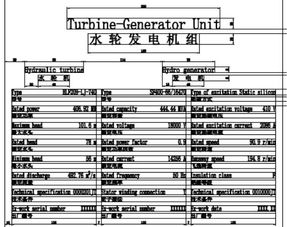
Figure 19-1 Sample of Rating Plate
(Son La HPP: Turbine-Generator Unit)
2. Sample of specifications for Labeling for electrical components
(1) Inscriptions
The labels will show the document reference number and functional name where applicable.
The lettering must be engraved in black in the English language unlessotherwise specified in the Technical Specifications.
Label material for major equipment must be stainless steel with black engraving or laminated plastic type with black core and white surface. All outdoor surface mounted labelsmust be stainless steel or laminated plastic type with black core and white surface.
Electrical devices within the compartmentmust be labeled with laminated plastic type with black core and white surface. The labelsmust be placed below the equipment and not on the equipment/devices.
All systems that are assembled in the factory must be delivered to site with the labels attached. Stainless steel / plasticlabels must be used to individually identify control and instrument panels, switchboards, motor control centers and junction boxes located outdoors unless otherwise specified in the Work Package Technical Specifications.
27
(2) Fastening systems
All labels must be securely fixed to the panels self-tapping screws. The use of adhesives is not permitted.
(3) Labeling of electrical main components / feeders
For the main equipment listed below, typical types of labels for electrical main components and its dimensions are shown herein:
Type A (example) |
|
Plate size: |
(w) 105 mm x (h) 37 mm x (t) 1.6 mm |
Letter size: |
8.0 mm |
Letter type: |
Arial, normal |
Usage: |
Panel door |
In addition to the external labels the components internal to Control Panels / Switchgearsneeds to be identified with Name plates as per manufacturer’s standard. These plates must be fitted not on the device but below the device so as to identify the component clearly.
Type B (example) |
|
|
|
Upper section line 1 : |
English text |
||
Upper section line 2 : |
Vietnamese text |
||
Lower section: |
Power Plant Identification |
||
Plate size: |
(w) 120mm x (h) 58mm x (t) 1.6mm |
||
Letter size: |
6 mm |
||
Letter type: |
Arial |
||
|
|
120 |
|
|
|
|
|
|
|
|
|
|
|
|
|
|
ENGLISH TEXT |
|
|
|
|
|
|
|
|
|
|
|
VIETNAMESE TEXT |
|
58 |
||
|
01MKA53GT001 |
|
|
|
|
Type C (example) |
|
|
|
|
|
Upper section : |
English text |
|
|
|
|
Lower section: |
Power Plant Identification |
|
|
|
|
Plate size: |
(w) 200mm x (h) 50mm x (t) 1.6mm |
|
|
|
|
28
Bigger letter size: |
14 mm |
Smaller letter size: |
12 mm |
Letter type: |
Arial |
Module doors |
|
Type D (example) |
|
Upper section line 1 : |
English text |
Upper section line 2 : |
Vietnamese text |
Lower section: |
Power Plant Identification |
Plate size: |
(w) 297 mm x (h)105 mm x (t)1.6 mm |
Bigger letter size: |
15 mm |
Smaller letter size: |
10 mm |
Letter type: |
Arial |
3. Label Selection Guideline (Reference)
No. |
Description |
Label Type |
|
|
|
1 |
Generator terminals and neutral point compartment |
A |
|
|
|
2 |
Bus duct |
A |
|
|
|
3 |
Generator circuit breaker system |
A |
|
|
|
4 |
Transformers |
B |
|
|
|
5 |
Emergency diesel generator |
A |
|
|
|
6 |
MV Switchgear cubicles |
C |
7 |
Control system cubicles |
C |
8 |
MCC cubicles |
C |
|
|
|
9 |
UPS cubicles |
C |
|
|
|
10 |
Generator protection cubicles |
C |
|
|
|
11 |
Static excitation and AVR cubicles |
D |
|
|
|
12 |
Synchronizing, measuring and metering cubicles |
C |
|
|
|
13 |
Fire protection cubicles |
C |
|
|
|
14 |
Module doors, General |
D |
|
|
|
15 |
Feeders, General |
A |
|
|
|
16 |
MCC Feeders, General |
A |
|
|
|
17 |
|
|
|
|
|
4.Example of Technical Specifications for reference
(1)Equipment Labeling of Ham Thuan - Da Mi HPP
1) Approved Labels
Approved labels, for example the ASME's label to the pressure vessel,must be attached to equipment where required by the regulating authority having jurisdiction or by the specified governing standard.
29
2) Nameplates
All Equipment must be suitably identified with nameplates. The name plate and warning label must be in English and/or Vietnamese language.
(a)Nameplates for indicating the name of panel, board, junction box, mustetc., be laminated plastic, screw fastened with black lettering on a white field. Minimum letter size to be 4 mm. Nameplates must be fitted in a prominent, readily accessible location.
(b)A permanent corrosion resistant metal nameplate showing the following information must be permanently mounted on each major piece of equipment:
-Equipment designation
-Manufacturer's name and address
-Serial number
-Part number
-Date of Manufacture
-Equipment ratings
3) Warning labels
The warning labels must be provided on or in all electrical equipment where terminals at dangerous voltages (including 400/230V) may be exposed during maintenance. Warning labels must be of plastic laminate with white lettering on a red background.
(2)Equipment’s Labels of Step-up Transformer of Son La HPP
1)General
a)The equipment supplier must provide labels with suitable size and sufficient details to permit rapid and positive identification to be made for operational and maintenance purposes of all pieces of equipment.
b)The identification plates must be protected during erection and especially during painting. New ones must replace damaged or illegible identification plates.
c)The inscription must be printed, punched, or engraved, and must be waterproof and oil-proof.
d)The following data must be shown in accordance with the relevant standards
-Manufacturer's name and address,
-Equipment serial number and date of manufacture,
-Main design data
e)A rating plate complying with the requirements of the appropriate Standard must be provided on each item of the equipment. In addition to the information listed in the appropriate Standard, the rating plate must be marked with the Contract number and other information requested by the Employer’s Representative. The rating platesmust be of engraved or stamped stainless steel or brass
30

2)Functional Plates / Labels
a)Each part appearing under a certain symbol or number in functional diagrams, piping diagrams, in the operation and maintenance instructions, etc., must be equipped with a plate/ label showing the same symbol or umber.
b)Valve labels must include a valve number of the form Faaaaa-bbb, where Faaaaa is the
schematic drawing number showing the valve and bbb is the valve number appearing on that drawing. Where relevant, valve labelsmust also include the notation“NO” or “NC” indicating whether the valve is normally open or normally closed. Fuses and links must be identified by their function, such asvoltage, polarity, phase color and fuse link rating.
5. Sample rating plate of 3 phase induction motor
Chapter 10 of IEC 60034-1 shall be referred to regarding items of rating plates for equipment of power facility. Sample rating plate of 3 phase induction motor is shown as follows ;
Table 19-1 Sample rating plate of 3 phase induction motor
Rated output |
15kW |
Type FGK |
|
|
|
Pole |
4 |
|
|
|
|
Rated voltage |
440V |
Insulation class F |
|
||
Rated current |
25.0A |
Rating |
Continuous |
|
|
Frequency |
60Hz |
Coolant temperature |
degree |
||
Speed |
1760 rpm |
Performance standard |
JEC2137 |
||
The rated open-circuit |
|
|
|
6224 |
|
voltage between slip-rings |
Bearing |
|
|
||
|
|
|
|||
|
|
number |
|
|
|
Rated slip-ring current |
|
|
6224 |
||
|
|
|
|||
|
|
|
|
|
|
|
|
The altitude |
|
m |
|
Degree of protection IP54 |
Year of manufacture |
2003-8 |
|||
Cooling type |
JC4F |
|
|
|
|
Serial number |
M 0111111 |
|
|
|
|
Figure 19- 2 Sample rating plate of generator
31

Article 20. Numbering of equipment
1. Purpose and application of numbering
(1)The purpose of numbering for all the apparatus, equipment, and facilities which are installed in an electric dispatching center or electric power plant is to make easy the design and construction supervision in the construction stage and the management in the operation and maintenance stage.
The numbering of apparatus, equipment and facilities contributes to the improvement of the certain and speedy transfer of information in the management of equipment by simplification and clear clarificationof the related documents, especiallypreparation of management drawings.
The nomenclatural type for the number of apparatus, equipment and facilities has been almost authorized by each purpose based on the international standards and the number ofthem is applied with coding of each facility.
(2)Type of piping, i.e., water supply and drainage pipes, pressure oil and drainage pipes, air supply and exhaust pipes, etc. must be expressed with colors and an arrow marks together with numbering in accordance with the purpose of equipment.
Example:
1) The following colors are applied for indicating piping system in general;
- |
Blue color |
: Water supply & drainage pipes |
- |
Red color |
: Pressure oil & drainage pipes |
- |
Brown |
: Air supply & exhaust pipes |
2)The following colors are applied for each phase of conductors installed in an electric power cable, a sealing bus-bar duct, and a transmission line in general;
-“Red, White and Blue” or “Black, White and Red” / “A, B, and C” or “R, S, and T” or “U, V, and W” phases. However, there are “Red, Yellow and Blue” in Vietnam as blow.
Photo 20-1 Sample numbering busduct and control panel
32
3)An device function number (sequence number) is applied in general to the switching apparatus and control device together with an equipment employment numbering or a marking.
“Regulation on numbering equipment of EVN(Document No.16/2007/QD-BCN, March 28th 2007 Minister: Ministry of Industry)” is described below as a sample:
Chapter VII Numbering equipments in national power system Article 37. Numbering with voltage level
1.500 kV level : numbered by 5
2.220 kV level : numbered by 2
3. |
110 kV level: |
numbered by 1 |
4. |
66 kV level : |
numbered by 7 |
5. |
35 kV level : |
numbered by 3 |
6. |
22 kV level : |
numbered by 4 |
7. |
15 kV level: |
numbered by 8 (Only with all generatorminalter voltage, synchronous |
|
|
machine |
|
|
15 kV are numbered by 9); |
8. |
10 kV level: |
numbered by 9 (Only with all generatorminalter voltage, synchronous |
|
|
machine |
|
|
10 kV are numbered by 9); |
9 |
6 kV level: |
numbered by 6 (with generator terminal voltage, synchronous machine upto |
|
|
10 kV are numbered by 6); |
10.Others voltage level will be self assigned by control dispatch level.
Article 38. Numbering bus-bar
1. The first symbol shall be assigned by letter C.
2. The second symbol show on voltage level, this symbol shall be assigned according to regulations in Article 37 of this documents.
3. The third symbol show on order number of bus bar, particular number 9 show on ring bus-bar. Example:
-C12: show on bus bar number 2, voltage level 110 kV;
-C21: show on bus bar number 1, voltage level 220 kV;
-C29: show on ring bus bar, voltage level 220 kV.
Article 39. Naming generator, synchronous machine
1.The first letter shall be regulated as follows:
a)With steam thermal power generator: assigned by letter S;
b)With hydro power generator: assigned by letter H;
c)With gas turbine: assigned by letter GT;
d)With the end of gas turbine: assigned by letter ST;
e)With diesel generator: assigned by letter D;
f)With synchronous machine: assigned by letter B;
g)With nuclear power: assigned by letter N;
33
h)With wind turbine: assigned by letter G;
i)With hydro power storage: assigned by letter P.
2.The second symbol is order number of generator.
Example:
-S1: show on generator number 1 of thermal power plant.
-GT2: show on gas turbine number 2.
-N1: show on generator number 1 of nuclear power plant.
Article 40. Naming transformer
1.The first symbol is regulated as follows:
a)Two or three winding transformer is assigned by letter T;
b)Auto-transformer is assigned by letter AT;
c)Auxiliary transformer is assigned by letter TD;
d)Exciting transformer is assigned by letter TE;
e)Neutral transformer is assigned by letter TT.
2.The following letter is order number of transformer. With auxiliary transformer, the following letters are voltage level and order number of transformer.
Example:
-T1: show on transformer number 1.
-T2: show on transformer number 2.
-TD31: show on auxiliary transformer with voltage level is 35 kV.
-AT1: show on auto-transformer number 1.
Article 41. Naming neutral resistor, neutral reactor of transformer
1.If two first letter are RT show on neutral resistor, KT are show on neutral reactor;
2.The third letter are taken on following to the voltage level of multi windings transformer;
3.The following letters are taken by name of transformer which RT or KT is connected.
Example:
-RT3T1: show on neutral resistor of 35kV winding of transformer named T1.
-KT5AT2: show on neutral reactor of 500kV transformer named AT2.
Article 42. Naming quadrature reactor
1.The first two letters are KH.
2.The third symbol show on voltage level, this symbol shall be assigned according to regulations in Article 37 of this documents.
3.The fourth symbol is number 0.
4.The fifth symbol is the order number of line that the quadrature reactor is connected.
Example:
- KH504: show on 500 kV quadrature reactor connected in line 4.
Article 43. Naming neutral reactor, neutral resistor of quadrature reactor
1.If the first two letters are RT show on neutral resistor, KT are show on neutral reactor of quadrature reactor.
2.The following symbols are taken on following three latest symbol of quadrature reactor.
34
Example:
-KT504: show on neutral reactor of quadrature reactor KH504.
-RT504: show on neutral resistor of quadrature reactor KH504.
Article 44. Naming Petersen coil
1.The first two symbols are KI.
2.The third symbol show on voltage level, this symbol shall be assigned according to regulations in Article 37 of this documents.
3. The following symbols are the order number of cable line or bus bar that thetor reacis connected.
Example:
-KI212: show on 220 kV petersen coil connected between bus bar number 1 and bus bar number 2.
-KI171: show on petersen coil of cable line 171.
Article 45. Naming reactor
1.The first symbol is L.
2.The following symbols are name of power line.
Example:
- L171: show on reactor of 110kV line named 171.
Article 46. Naming compensating capacitor
1. The first three symbols: with series capacitor are TBD, with shunt capacitor are TBN.
2. The fourth symbol show on voltage level, this symbol shall be assigned according to regulations in Article 37 of this documents.
3.The fifth symbol is zero (0).
4.The sixth symbol is order number of line that thesries capacitor is connected, or is order number of capacitor with shunt capacitor.
Example:
-TBD501: show on 500 kV series capacitor connected in line number 1.
-TBN302: show on 35 kV shunt capacitor connected in line number 2.
Article 47. Naming high voltage prevent capacitor
1.The first symbol is C;
2.The following symbols are name of protected equipment. With protected equipment that it’s
voltage level do not show clearly in it’s name, after first symbol is the specific symbol of voltage level and the latest is name of equipment.
Example:
-C901: show on high voltage prevent capacitor of circuit breaker named 901.
-C9H1: show on high voltage prevent capacitor connected to terminal voltage side of generator named H1.
Article 48. Naming Voltage transformer
1.The first symbol is TU;
2.The following symbols are name of equipment that the voltage transformer is connected. With protected equipment that it’s voltage level do not show clearly in it’s name, after first symbol is the specific symbol of voltage level and the latest is name of equipment.
35
Example:
-TU171: show on voltage transformer of 110kV line named 171.
-TUC22: show on voltage transformer of 220kV bus bar number 2.
-TU5T2: show on voltage transformer on 500kV side of transformer named T2.
Article 49. Naming current transformer
1.The first two symbols are TU;
2.The following symbols are name of equipment that the voltage transformer is connected. With protected equipment that it’s voltage level do not show clearly in it’s name, after first symbol is the specific symbol of voltage level and the latest is name of equipment.
Example:
-TI171: show on 110kV current transformer of line 171.
-TI5AT2: show on 500kV bushing current transformer of auto transformer named AT2.
Article 50. Naming surge arrester
1.The first two symbols are CS;
2.The following symbols are name of protected equipment. With protected equipment that it’s
voltage |
level |
do |
not |
show |
clearly in |
it’s name, after first symbol is |
the specific symbol |
of |
voltage |
level |
and |
the |
latest |
is name |
of equipment. With surge arrester |
that is connected |
to |
neutral of transformer, voltage level is assigned by zero (0). Example:
-CS1T1: show on surge arrester on 110kV side of transformer named T1.
-CS0T1: show on surge arrester connected in neutral of transformer named T1.
-CS271: show on surge arrester of line 271.
Article 51. Naming fuse
1.The first symbols: with normal fuse are CC, with fuse cut-out are FCO.
2.The following symbols are symbol (-) and name of protected equipment.
Example: CC-TUC31: show on fuse of voltage transformer on busbar named C31.
Article 52. Numbering circuit breaker
1.The first symbol show on voltage level, this symbol shall be assigned according to regulations in Article 37 of this documents. Only with circuit breaker of capacitor is assigned by T, with reactor the first symbol is K and the second symbol is designated to voltage level.
2.The second symbol (three symbol with circuit breaker of capacitor and reactor) is designated to location of circuit breaker and regulated as follows:
a) |
Circuit breaker of transformer |
: numbered by 3. |
b) |
Circuit breaker of power line |
: numbered by 7 and 8 (or from 5 to 8 if |
|
connecting diagram is complicate). |
|
c) |
Circuit breaker of auxiliary transformer |
: numbered by 4. |
d) |
Terminal circuit breaker of generator |
: numbered by 0. |
e) |
Circuit breaker of synchronous machine |
: numbered by 0. |
f) |
Circuit breaker of shunt capacitor |
: numbered by 0. |
g) |
Circuit breaker of series capacitor |
: numbered by (or by 9 if connecting |
|
diagram is complicate). |
|
36
h) Circuit breaker of reactor |
: numbered by (or by 9 if connecting diagram is |
complicate). |
|
3.The third symbol (fourth with circuit breaker of reactor or capacitor) show on order number. E.g: 1,2,3...
4.With circuit breaker of ring bus bar, two symbols after the first are: 00.
5.With communication circuit breaker between two bus bars, two symbols after the first are order numbers of two bus bars.
6.With sectionalized bus bar diagram, numbering circuit breakers on even bus bar by even numbers, and by odd numbers with circuit breakers on odd bus bar.
7.With polygonal diagram, numbering circuit breakers following to line circuit breakers;
8.With 3/2 diagram, 4/3 diagram: circuit breakers can be numbered by following method depend on diagrams:
a)Numbering circuit breakers following to line circuit breakers;
b)Numbering two circuit breakers in centre (do not connect with bus bars) by num ber 5 or number 6.
c)Numbering the third number according to order number of line.
Example:
-131: show on 110kV circuit breaker number 1 of transformer.
-903: show on terminal generator circuit breaker number 3, voltage level is 10 kV.
-K504: show on circuit breaker number 4 of 500 kV reactor.
-100: show on 110kV circuit breaker of ring bus bar.
-212: show on communication circuit breaker of 220kV bus bars.
Article 53. Numbering disconnector
1.The first symbols are name of circuit breaker or name of equipment directly connect to disconnector (with disconnector of voltage transformer, the first symbols are name of voltage transformer, after that is name of equipment that is directly connected to dis-connector), after that is (-) symbol.
2.Following symbol is regulated as follows:
a)Order number of bus bar that disconnector is connected with disconnector bus bar;
b)Line disconnector is numbered 7;
c)Disconnector connect to transformer is numbered 3;
d)Disconnector connect to ring bus bar is numbered 9;
e)Earthing disconnector of an equipment is numbered 0 or 9;
f)With sectionalized disconnector is numbered by order number of sectionalized bus bar that is connected.
g)Disconnector connected to neutral resistor or neutral reactor is numbered 0.
Example:
-131-3: show on 110 kV disconnector of transformer T1.
-K501-1: show on 500kV disconnector of reactor number 1 connected to bus bar number 1.
37
-TUC22-2: show on 220 kV disconnector of transformer number 2 connected to bus bar number 2.
-171-7: show on 110 kV line disconnector of circuit breaker named 171.
-272-9: show on disconnector of circuit breaker named 272 that connected to ring bus bar.
-275-0: show on earthing disconnector of circuit breaker named 275.
-KT101-0: show on disconnector in neutral of 110kVwindings of transformer T1 that is connected to reactor named KT101.
Article 54. Numbering earthing disconnector
1.First symbols are name of disconnector or direct relating equipment.
2.The following symbol is designated to earthing disconnector, and is regulated as follows:
a)Earthing disconnector of line or capacitor is numbered 6;
b)Earthing disconnector of transformer, reactor and voltage transformer is numbered 8;
c)Earthing disconnector of circuit breaker is numbered 5;
d)Earthing disconnector of bus bar is numbered 4;
e)Earthing disconnector in neutral of transformer or reactor is numbered 08.
Example:
-271-76: show on earthing disconnector in line named 271.
-171-15: show on earthing disconnector of circuit breaker named 171 in disconnector named 171-1.
-131-08: show on earthing disconnector in neutral of 110kV wingding of transformer number 1.
2.Example of numbering system
(1)Sample for Color bands and Arrows
Adhesive tape color banding must be used only for insulatedpiping, stainless steel pipes and hot galvanized pipes.
Banding is not applied for noni-sulated piping. The arrowmust be painted onto theno insulated piping surface.
All piping will be labeled by stenciling its designated system name. Words must be stenciled in black on white background.
Where piping is located above or below the normal line of vision, the letteringmust be placed below or above the horizontal centerline of the pipe
Sizes of letters for piping above or below the normal line of vision are as follows in general:
38
Table 20-1 Size of Letters for Piping
Pipe Sizes |
Length of Color Field |
Size of Letter |
|
|
|
13 mm up to 40 mm |
200 mm |
13 mm |
|
|
|
50 mm to 100 mm |
200 mm |
19 mm |
|
|
|
150 mm |
300 mm |
32 mm |
|
|
|
200 mm larger |
600 mm |
64 mm |
|
|
|
All systems that are assembled in the factory must be delivered to site with the labels affixed. The color bands and arrow must be indicated on all insulated pipes at the following locations:
-Tank inlets and outlets
-Pumps discharge and suction
-Loading and unloading connection (lorry loading, drum loading, cylinder loading, etc)
-Next to each valve
-Inlets and outlets of underground and pipe trenches
-Upper and lower ends of pipe floor penetration
-Adjacent to changes in direction and branches
The location of thecolor banding and arrows forlong straight pipeswill be at 12 meter intervals in general. For shorter pipe length the distances can be reduced to 6meter to enable clear identification of the pipes and direction of flow.
The color band and the flow direction will be in accordance with Painting Specification in the Contract.
Color band and arrow tapesmust be of durable dimensionally stable, glossy vinyl film with pressure sensitive (self-sticking) adhesive and itmust be suitable for outdoor, applicable in tropical environment.
Color of directional arrow for non-insulated piping must be in good contrast to the basic color. Color band and directional arrow dimensions must be as follows:
39
|
t |
|
ф |
w |
h2 |
|
I1 |
I2 |
|
|
|
|
|
(Unit : mm) |
|
|
|
|
|
|
|
|
ф(Pipe Sizes) |
h2 |
t |
l1 |
l2 |
|
w |
|
|
|
|
|
|
|
50 mm to 150 mm |
40 |
25 |
75 |
35 |
|
50 |
|
|
|
|
|
|
|
Above 150 mm |
60 |
40 |
100 |
50 |
|
75 |
|
|
|
|
|
|
|
Figure 20-2 Dimensions of Color Band & Directional Arrow
Photo 20-2 Example of Directional Arrow1
(2) Sample for Device Function Numbers
The device function numbers(DFN) will be applied in accordance with IEEE (ANSI), BS, JEM (in Japan), etc., of International standards for each piece of equipment of electric power facility, as AttachedTable 20-2 Comparison of Device Function Numbers(for Reference)
Table 20-2 Comparison of Device Function Numbers
(For Reference)
Function |
JEM 1091 |
IEEE C37.2 |
BS-3939 |
Number |
(2008) |
(1970) |
(1970) |
|
|
|
|
|
MASTER ELEMENT |
|
|
1 |
(MASTER SWITCHING |
MASTER ELEMENT |
MASTER ELEMENT |
|
DEVICE) |
|
|
|
|
|
|
40
Function |
JEM 1091 |
IEEE C37.2 |
BS-3939 |
|
Number |
(2008) |
(1970) |
(1970) |
|
|
|
|
|
|
2 |
TIME-DELAY STARTING |
TIME-DELAY STARTING |
TIME-DELAY STARTING |
|
OR CLOSING RELAY |
OR CLOSING RELAY |
OR CLOSING RELAY |
||
|
||||
|
|
|
|
|
3 |
CONTROL SWITHCH |
CHECKING OR |
CHECKING OR |
|
INTERLOCKING RELAY |
INTERLOCKING RELAY |
|||
|
|
|||
|
|
|
|
|
4 |
MASTER CONTACTOR OR |
MASTER CONTACTOR |
MASTER CONTACTOR |
|
RELAY |
||||
|
|
|
||
|
|
|
|
|
5 |
STOPPING DEVICE |
STOPPING DEVICE |
STOPPING DEVICE |
|
|
|
|
|
|
|
STARTING CIRCUIT |
STARTING CIRCUIT |
STARTING CIRCUIT |
|
6 |
BREAKER CONTACTOR OR |
|||
BREAKER |
BREAKER |
|||
|
RELAY |
|||
|
|
|
||
|
|
|
|
|
7 |
ANODING SWITCH |
ANODE CIRCUIT |
ANODE CIRCUIT |
|
BREAKER |
BREAKER |
|||
|
|
|||
|
|
|
|
|
8 |
CONTROL POWER SWITCH |
CONTROL POWER |
CONTROL POWER |
|
DISCONNECTING DEVICE |
DISCONNECTING DEVICE |
|||
|
|
|||
|
|
|
|
|
9 |
REVERSING DEVICE |
REVERSING DEVICE |
REVERSING DEVICE |
|
|
|
|
|
|
10 |
UNIT SEQUENCE SWITCH |
UNIT SEQUENCE SWITCH |
UNIT SEQUENCE SWITCH |
|
|
|
|
|
|
11 |
TESTING SWITCH |
[RESERVED] |
[RESERVED] |
|
|
|
|
|
|
12 |
OVERSPEED DEVICE |
OVERSPEED DEVICE |
OVERSPEED DEVICE |
|
|
|
|
|
|
13 |
SYNCHRONOUS-SPEED |
SYNCHRONOUS-SPEED |
SYNCHRONOUS-SPEED |
|
DEVICE |
DEVICE |
DEVICE |
||
|
||||
|
|
|
|
|
14 |
UNDERSPEED DEVICE |
UNDERSPEED DEVICE |
UNDERSPEED DEVICE |
|
|
|
|
|
|
15 |
SPEED OR FREQUENCY |
SPEED OR FREQUENCY |
SPEED OR FREQUENCY |
|
MATCHING DEVICE |
MATCHING DEVICE |
MATCHING DEVICE |
||
|
||||
|
|
|
|
|
16 |
PILOT-WIRE-FAULT |
[RESERVED] |
[RESERVED] |
|
PROTECTIVE RELAY |
||||
|
|
|
||
|
|
|
|
|
17 |
PILOT-WIRE RELAY |
SHUNTING OR |
SHUNTING OR |
|
DISCHARGE SWITCH |
DISCHARGE SWITCH |
|||
|
|
|||
|
|
|
|
|
18 |
ACCELERATING OR |
ACCELERATING OR |
ACCELERATING OR |
|
DECELERATING DEVICE |
DECELERATING DEVICE |
DECELERATING DEVICE |
||
|
||||
|
|
|
|
|
|
STARTING-TO-RUNNING |
STARTING-TO-RUNNING |
STARTING-TO-RUNNING |
|
19 |
TRANSITION CONTACTOR |
|||
TRANSITION CONTACTOR |
TRANSITION CONTACTOR |
|||
|
OR RELAY |
|||
|
|
|
||
|
|
|
|
|
20 |
VALVE FOR AUXILIARY |
ELECTRICALLY |
VALVE |
|
APPARTUS |
OPERATED VALVE |
|||
|
|
|||
|
|
|
|
|
21 |
VALVE FOR MAIN |
DISTANCE RELAY |
DISTANCE RELAY |
|
MACHINE |
||||
|
|
|
||
|
|
|
|
|
22 |
[RESERVED] |
EQUALIZER CIRCUIT |
EQUALIZER CIRCUIT |
|
BREAKER |
BREAKER |
|||
|
|
|||
|
|
|
|
|
23 |
TEMPERATURE CONTROL |
TEMPERATURE CONTROL |
TEMPERATURE CONTROL |
|
DEVICE (RELAY) |
DEVICE |
DEVICE |
||
|
||||
|
|
|
|
|
24 |
TAP CHANGING |
[RESERVED] |
[RESERVED] |
|
MECHANISM |
||||
|
|
|
||
|
|
|
|
41

Function |
JEM 1091 |
IEEE C37.2 |
BS-3939 |
|
Number |
(2008) |
(1970) |
(1970) |
|
|
|
|
|
|
|
SYNCHRONIZING OR |
SYNCHRONIZING OR |
SYNCHRONIZING OR |
|
25 |
SYNCHRONISM-CHECK |
SYNCHRONISM-CHECK |
SYNCHRONISM-CHECK |
|
|
DEVICE |
DEVICE |
DEVICE |
|
|
|
|
|
|
26 |
THERMAL RELAY FOR |
APPARATUS THERMAL |
APPARATUS THERMAL |
|
STATIONARY APPARATUS |
DEVICE |
DEVICE |
||
|
||||
|
|
|
|
|
27 |
AC UNDERVOLTAGE |
UNDERVOLTAGE RELAY |
UNDERVOLTAGE RELAY |
|
RELAY |
||||
|
|
|
||
|
|
|
|
|
28 |
ALARM DEVICE |
FLAME DETECTOR |
FLAME DETECTOR |
|
|
|
|
|
|
29 |
FIRE EXTINGUISHER |
ISOLATING CONTACTOR |
ISOLATING CONTACTOR |
|
|
|
|
|
|
30 |
ANNUNCIATOR |
ANNUNCIATOR RELAY |
ANNUNCIATOR RELAY |
|
|
|
|
|
|
|
FIELD TRANSFORMER OF |
|
|
|
31 |
FIELD CHANGING |
SEPARATE EXCITATION |
SEPARATE EXCITATION |
|
BREAKER CONTACTOR OR |
DEVICE |
DEVICE |
||
|
||||
|
RELAY |
|
|
|
|
|
|
|
|
32 |
DC REVERSE CURRENT |
DIRECTIONAL POWER |
DIRECTIONAL POWER |
|
RELAY |
RELAY |
RELAY |
||
|
||||
|
|
|
|
|
|
POSITION SWITCH OR |
|
|
|
33 |
POSITION-DE-TECTING |
POSITION SWITCH |
POSITION SWITCH |
|
|
DEVICE |
|
|
|
|
|
|
|
|
34 |
MOTOR OPERATED |
MASTER SEQUENCE |
MASTER SEQUENCE |
|
SEQUENCE SWITCH |
DEVICE |
DEVICE |
||
|
||||
|
|
|
|
|
|
BRUSH-OPERATING OR |
BRUSH-OPERATING OR |
BRUSH-OPERATING OR |
|
35 |
SLIP RING SHORT- |
SLIP RING SHORT- |
SLIP RING SHORT- |
|
|
CIRCUITING DEVICE |
CIRCUITING DEVICE |
CIRCUITING DEVICE |
|
|
|
|
|
|
|
|
POLARITY OR |
POLARITY OR |
|
36 |
POLARITY RELAY |
POLARIZING VOLTAGE |
POLARIZING VOLTAGE |
|
|
|
DEVICE |
DEVICE |
|
|
|
|
|
|
37 |
UNDERCURRENT RELAY |
UNDERCURRENT OR |
UNDERCURRENT OR |
|
UNDER POWER RELAY |
UNDER POWER RELAY |
|||
|
|
|||
|
|
|
|
|
38 |
BEARING EXCESSIVE |
BEARING PROTECTIVE |
BEARING PROTECTIVE |
|
TEMPERATURE RELAY |
DEVICE |
DEVICE |
||
|
||||
|
|
|
|
|
39 |
[RESERVED] |
MECHANICAL CONDITION |
MECHANICAL CONDITION |
|
MONITOR |
MONITOR |
|||
|
|
|||
|
|
|
|
|
40 |
FIELD CURRENT RELAY |
FIELD RELAY |
FIELD RELAY |
|
OR LOSS FIELD RELAY |
||||
|
|
|
||
|
|
|
|
|
41 |
FIELD CIRCUIT BREAKER |
FIELD CIRCUIT BREAKER |
FIELD CIRCUIT BREAKER |
|
CONTACTOR OR SWITCH |
||||
|
|
|
||
|
|
|
|
|
|
RUNNING CIRCUIT |
RUNNING CIRCUIT |
RUNNING CIRCUIT |
|
42 |
BREAKER CONTACTOR OR |
|||
BREAKER |
BREAKER |
|||
|
SWITCH |
|||
|
|
|
||
|
|
|
|
|
43 |
MANUAL TRANSFER OR |
MANUAL TRANSFER OR |
MANUAL TRANSFER OR |
|
SELECTOR SWITCH |
SELECTOR DEVICE |
SELECTOR DEVICE |
||
|
||||
|
|
|
|
|
44 |
DISTANCE RELAY |
UNIT SEQUENCE |
UNIT SEQUENCE |
|
STARTING RELAY |
STARTING RELAY |
|||
|
|
|||
|
|
|
|
42
Function |
JEM 1091 |
IEEE C37.2 |
BS-3939 |
|
Number |
(2008) |
(1970) |
(1970) |
|
|
|
|
|
|
45 |
DC OVEROLTAGE RELAY |
ATMOSPHERIC |
ATMOSPHERIC |
|
CONDITION MONITOR |
CONDITION MONITOR |
|||
|
|
|||
|
|
|
|
|
|
REVERSE-PHASE OR |
REVERSE-PHASE OR |
REVERSE-PHASE OR |
|
46 |
PHASE-BALANCE |
PHASE-BALANCE |
PHASE-BALANCE |
|
|
CURRENT RELAY |
CURRENT RELAY |
CURRENT RELAY |
|
|
|
|
|
|
47 |
OPEN OR REVERSE PHASE |
PHASE-SEQUENCE |
PHASE-SEQUENCE |
|
VOLTAGE RELAY |
VOLTAGE RELAY |
VOLTAGE RELAY |
||
|
||||
|
|
|
|
|
48 |
INCOMPLETE SEQUENCE |
INCOMPLETE SEQUENCE |
INCOMPLETE SEQUENCE |
|
RELAY |
RELAY |
RELAY |
||
|
||||
|
|
|
|
|
49 |
THERMAL RELAY FOR |
MACHINE OR |
MACHINE OR |
|
TRANSFORMER THERMAL |
TRANSFORMER THERMAL |
|||
ROTATING MACHINE |
||||
|
RELAY |
RELAY |
||
|
|
|||
|
|
|
|
|
|
SHORT-CIRCUIT |
INSTANTANEOUS |
INSTANTANEOUS |
|
50 |
SELECTIVE RELAY OR |
|||
OVERCURRENT OR RATE- |
OVERCURRENT OR RATE- |
|||
GROUND SELECTIVE |
||||
|
OF-RISE RELAY |
OF-RISE RELAY |
||
|
RELAY |
|||
|
|
|
||
|
|
|
|
|
|
AC OVERCURRENT RELAY |
AC TIME OVERCURRENT |
AC TIME OVERCURRENT |
|
51 |
OR GROUND |
|||
RELAY |
RELAY |
|||
|
OVERCURRENT RELAY |
|||
|
|
|
||
|
|
|
|
|
52 |
AC CIRCUIT BREAKER OR |
AC CIRCUIT BREAKER |
AC CIRCUIT BREAKER |
|
CONTACTOR |
||||
|
|
|
||
|
|
|
|
|
53 |
EXCITATION RELAY |
EXCITER OR AC |
EXCITER OR AC |
|
GENERATOR RELAY |
GENERATOR RELAY |
|||
|
|
|||
|
|
|
|
|
54 |
HIGH-SPEED DC CIRCUIT |
[RESERVED] |
[RESERVED] |
|
BREAKER |
||||
|
|
|
||
|
|
|
|
|
|
AUTOMATIC POWER |
|
|
|
55 |
FACTOR REGULATOR OR |
POWER FACTOR RELAY |
POWER FACTOR RELAY |
|
|
POWER FACTOR RELAY |
|
|
|
|
|
|
|
|
56 |
SLIP-RELAY OR OUT-OF- |
FIELD APPLICATION |
FIELD APPLICATION |
|
STEP RELAY |
RELAY |
RELAY |
||
|
||||
|
|
|
|
|
|
AUTOMATIC CURRENT |
SHORT-CIRCUITING OR |
SHORT-CIRCUITING OR |
|
57 |
REGULATOR OR CURRENT |
|||
GROUNDING DEVICE |
GROUNDING DEVICE |
|||
|
RELAY |
|||
|
|
|
||
|
|
|
|
|
58 |
[RESERVED] |
RECTIFICATION FAILURE |
RECTIFICATION FAILURE |
|
RELAY |
RELAY |
|||
|
|
|||
|
|
|
|
|
59 |
AC OVERVOLTAGE RELAY |
OVERVOLTAGE RELAY |
OVERVOLTAGE RELAY |
|
|
|
|
|
|
|
AUTOMATIC VOLTAGE |
|
|
|
60 |
BALANCE REGULATOR OR |
VOLTAGE OR CURRENT |
VOLTAGE OR CURRENT |
|
VOLTAGE BALANCE |
BALANCE RELAY |
BALANCE RELAY |
||
|
||||
|
RELAY |
|
|
|
|
|
|
|
|
|
AUTOMATIC CURRENT |
|
|
|
61 |
BALANCE REGULATOR OR |
[RESERVED] |
[RESERVED] |
|
CURRENT BALANCE |
||||
|
|
|
||
|
RELAY |
|
|
|
|
|
|
|
43
Function |
JEM 1091 |
IEEE C37.2 |
BS-3939 |
|
Number |
(2008) |
(1970) |
(1970) |
|
|
|
|
|
|
62 |
TIME-DELAY STOPPING |
TIME-DELAY STOPPING |
TIME-DELAY STOPPING |
|
OR STARTING RELAY |
OR STARTING RELAY |
OR STARTING RELAY |
||
|
||||
|
|
|
|
|
63 |
PRESSURE RELAY |
PRESSURE SWITCH |
LIQUID OR GAS PRESSURE |
|
OR VACUUM RELAY |
||||
|
|
|
||
|
|
|
|
|
64 |
GROUND OVERVOLTAGE |
GROUND PROTECTIVE |
EARTH-FAULT |
|
RELAY |
RELAY |
PROTECTIVE RELAY |
||
|
||||
|
|
|
|
|
65 |
GOVERNOR |
GOVERNOR |
GOVERNOR |
|
|
|
|
|
|
66 |
NOTCHING OF FLASHING |
NOTCHING OR JOGGING |
NOTCHING OR JOGGING |
|
RELAY |
DEVICE |
DEVICE |
||
|
||||
|
|
|
|
|
|
AC POWER DIRECTIONAL |
AC DIRECTIONAL |
AC DIRECTIONAL |
|
67 |
OR AC GROUND |
|||
OVERCURRENT RELAY |
OVERCURRENT RELAY |
|||
|
DIRECTIONAL RELAY |
|||
|
|
|
||
|
|
|
|
|
68 |
IMPURITY-DETECTING |
BLOCKING RELAY |
BLOCKING RELAY |
|
RELAY |
||||
|
|
|
||
|
|
|
|
|
69 |
FLOW RELAY |
PERMISSIVE CONTROL |
PERMISSIVE CONTROL |
|
DEVICE |
DEVICE |
|||
|
|
|||
|
|
|
|
|
70 |
ADJUSTING RHEOSTAT |
RHEOSTAT |
RHEOSTAT |
|
|
|
|
|
|
|
RECTIFIER ELEMEMT |
|
LIQUID OR GAS-LEVEL |
|
71 |
PROTECTIVE RELAY OR |
LEVEL SWITCH |
||
RELAY |
||||
|
DEVICE |
|
||
|
|
|
||
|
|
|
|
|
72 |
DC CIRCUIT BREAKER OR |
DC CIRCUIT BREAKER |
DC CIRCUIT BREAKER |
|
CONTACTOR |
||||
|
|
|
||
|
|
|
|
|
73 |
LOAD RESISTOR CIRCUIT |
LOAD-RESISTOR |
LOAD-RESISTOR |
|
BREAKER OR CONTACTOR |
CONTACTOR |
CONTACTOR |
||
|
||||
|
|
|
|
|
74 |
REGULATING VALVE |
ALARM RELAY |
ALARM RELAY |
|
|
|
|
|
|
75 |
BREAKING DEVICE |
POSITION-CHANGING |
POSITION-CHANGING |
|
MECHANISM |
MECHANISM |
|||
|
|
|||
|
|
|
|
|
76 |
DC OVERCURRENT RELAY |
DC OVERCURRENT RELAY |
DC OVERCURRENT RELAY |
|
|
|
|
|
|
77 |
LOAD REGULATING |
PULSE TRANSMITTER |
PULSE TRANSMITTER |
|
DEVICE |
||||
|
|
|
||
|
|
|
|
|
|
PHASE COMPARISON |
PHASE-ANGLE |
PHASE-ANGLE |
|
78 |
RELAY OF PILOT |
MEASURING OR OUT-OF- |
MEASURING OR OUT-OF- |
|
|
PROTECTION |
STEP PROTECTIVE RELAY |
STEP PROTECTIVE RELAY |
|
|
|
|
|
|
79 |
AC RECLOSING RELAY |
AC RECLOSING RELAY |
AC RECLOSING RELAY |
|
|
|
|
|
|
80 |
DC UNDERVOLTAGE |
FLOW SWITCH |
LIQUID OR GAS FLOW |
|
RELAY |
RELAY |
|||
|
|
|||
|
|
|
|
|
81 |
SPEED GOVERNOR |
FREQUENCY RELAY |
FREQUENCY RELAY |
|
DRIVING DEVICE |
||||
|
|
|
||
|
|
|
|
|
82 |
DC RECLOSING RELAY |
DC RECLOSING RELAY |
DC RECLOSING RELAY |
|
|
|
|
|
|
|
AUTOMATIC SELECTIVE |
AUTOMATIC SELECTIVE |
AUTOMATIC SELECTIVE |
|
83 |
CONTROL OR TRANSFER |
CONTROL OR TRANSFER |
CONTROL OR TRANSFER |
|
|
CONTACTOR OR RELAY |
RELAY |
RELAY |
|
|
|
|
|
44
Function |
JEM 1091 |
IEEE C37.2 |
BS-3939 |
|
Number |
(2008) |
(1970) |
(1970) |
|
|
|
|
|
|
84 |
VOLTAGE RELAY |
OPERATING MECHANISM |
OPERATING |
|
|
|
|
|
|
85 |
SIGNAL RELAY |
CARRIER OR PILOT-WIRE |
CARRIER OR PILOT-WIRE |
|
RECEIVER RELAY |
RECEIVER RELAY |
|||
|
|
|||
|
|
|
|
|
86 |
LOCKING-OUT RELAY |
LOCKING-OUT RELAY |
LOCKING-OUT RELAY |
|
|
|
|
|
|
87 |
DIFFERENTIAL CURRENT |
DIFFERENTIAL |
DIFFERENTIAL |
|
RELAY |
PROTECTIVE RELAY |
PROTECTIVE RELAY |
||
|
||||
|
|
|
|
|
88 |
AUXILIARY CONTACTOR |
AUXILIARY MOTOR OR |
AUXILIARY MOTOR OR |
|
OR SWITCH |
MOTOR GENERATOR |
MOTOR GENERATOR |
||
|
||||
|
|
|
|
|
|
LINE SWITCH |
LINE SWITCH |
LINE SWITCH |
|
89 |
(DISCONNECTING |
(DISCONNECTING |
(DISCONNECTING |
|
|
SWITCH) |
SWITCH) |
SWITCH) |
|
|
|
|
|
|
|
AUTOMATIC VOLTAGE |
|
|
|
90 |
REGULATOR OR |
REGULATING DEVICE |
REGULATING DEVICE |
|
|
REGULATING RELAY |
|
|
|
|
|
|
|
|
|
AUTOMATIC POWER |
VOLTAGE DIRECTIONAL |
VOLTAGE DIRECTIONAL |
|
91 |
REGULATOR OR POWER |
|||
RELAY |
RELAY |
|||
|
RELAY |
|||
|
|
|
||
|
|
|
|
|
92 |
DOOR |
VOLTAGE AND POWER |
VOLTAGE AND POWER |
|
DIRECTIONAL RELAY |
DIRECTIONAL RELAY |
|||
|
|
|||
|
|
|
|
|
93 |
[RESERVED] |
FIELD-CHANGING |
FIELD-CHANGING |
|
CONTACTOR |
CONTACTOR |
|||
|
|
|||
|
|
|
|
|
94 |
TRIP-FREE RELAY |
TRIPPING OR TRIP-FREE |
TRIPPING OR TRIP-FREE |
|
RELAY |
RELAY |
|||
|
|
|||
|
|
|
|
|
|
AUTOMATIC FREQUENCY |
USED ONLY FOR SPECIFIC |
USED ONLY FOR SPECIFIC |
|
95 |
REGULATOR OR |
|||
APPLICATIONS |
APPLICATIONS |
|||
|
FREQUENCY RELAY |
|||
|
|
|
||
|
|
|
|
|
|
INTERNAL FAULT |
|
|
|
96 |
DETECTING DEVICE FOR |
Some as above |
Some as above |
|
|
STATIONARY APPARATUS |
|
|
|
|
|
|
|
|
97 |
RUNNER |
Some as above |
Some as above |
|
|
|
|
|
|
98 |
CONNECTING DEVICE |
Some as above |
Some as above |
|
|
|
|
|
|
99 |
AUTOMATIC RECORDING |
Some as above |
Some as above |
|
DEVICE |
||||
|
|
|
||
|
|
|
|
(3) Objective of numbering system
The objective of numbering system is to identifyequipment, installation location and purpose of use.
Sample cable number is shown as follows;.
45
<Sample cable number : G21M11>
Cable No. |
G |
|
21 |
M |
|
1 |
1 |
||
|
|
|
|
|
|
|
|
|
|
|
Classification |
|
Page of the |
Circuit type |
|
Cable circuit |
|
||
|
of sequence |
|
|
|
|||||
Item |
|
sequence |
symbol |
|
Unit number |
||||
diagram |
|
|
number |
||||||
|
|
diagram |
(Note 1) |
|
|
||||
|
symbol |
|
|
|
|
|
|||
|
|
|
|
|
|
|
|
|
|
|
|
|
|
|
|
|
|
|
|
*Note 1 : Circuit type symbol |
|
|
|
|
|
|
|
||
|
|
|
|
|
|
|
|
|
|
CT circuit |
|
|
|
|
|
C |
|
|
|
|
|
|
|
|
|
|
|
|
|
PT circuit |
|
|
|
|
|
V |
|
|
|
|
|
|
|
|
|
|
|
|
|
Motor circuit |
|
|
|
|
|
M |
|
|
|
|
|
|
|
|
|
||||
Shield for instrumentation and control circuit |
|
|
Z |
|
|
||||
|
|
|
|
|
|
||||
Other special circuit compensating lead wire |
|
|
H |
|
|
||||
|
|
|
|
|
|
|
|||
AC circuit other than the above |
|
|
|
A |
|
|
|||
|
|
|
|
|
|
|
|||
DC circuit other than the above |
|
|
|
D |
|
|
|||
|
|
|
|
|
|
|
|
|
|
Article 21. Record and Indication of parameter for operation
1.The measured data is displayed in the control panel or CRT (Cathode Ray Tube), in general. Measurement items specified in the Technical Regulation Vol.2 or others must be displayed in the control panel or CRT.
2.In principle, the measured data is recommended to be saved during the required period, because the data is useful for the maintenance and inspection. In many cases, data is saved as electronic data because of easiness for searching and saving. However, period of data storage is limited by the memory capacity; therefore, it is desirable to consider the sampling period in order to save the data during the required period.
3.The data on laws or security (items specified in the technical regulation Vol2 or others) is required to be stored during the existence of facility or organization.
In this case, data is stored by documents such as thechart recorder and reports of operation and security, in general.
46
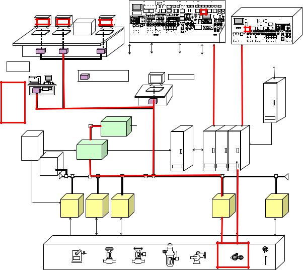
|
|
Monitor desk |
Auxiliary panel |
|
|
|
|
|
|
|
|
|
|
Console |
|
|
|
panel |
|
Key boad |
|
|
oiler urbine enerator monitor panel |
|
|
|
|
|
To |
|
|
Fuel |
Turbine |
|
head |
For |
|
control unit |
control unit |
|
office |
Maintainanc |
|
|
|
|
communiacation |
|
|
|
|
||
|
Computer for CRT |
|
For supervisor |
|
panel |
|
|
|
|
|
|
|
|
|
|
|
|
|
|
|
Outp |
|
|
|
|
|
Key boad |
|
|
|
ut |
of |
|
|
|
|
|
|
|
|
|
Key boad |
|
|
|
|
|
|
||
repor |
|
|
|
|
|
Computer |
Auxiliary relay |
|
|
|
|
|
|
|
|
|
Auxiliary |
panel |
|
|
|
|
|
|
|
|
panel |
|
|
|
|
|
|
|
|
To |
|
|
|
|
|
|
|
|
|
|
|
|
|
|
|
|
|
|
Office |
head |
|
|
|
|
|
|
|
|
Computer |
office |
|
|
|
|
|
|
|
Computer |
|
|
|
|
|
|
|
|
|
|
|
|
|
|
|
|
|
|
|
Server |
|
|
|
|
|
|
|
|
Voice |
|
|
|
|
|
|
|
|
|
unit |
|
|
|
|
|
|
|
|
|
|
Fuel |
Turbine |
|
|
Sequence |
/ |
|
|
|
|
|
|
|
|||
|
|
|
control |
control |
|
|
control |
||
|
|
|
|
|
|
|
|||
|
|
|
|
|
|
Field |
|
|
|
M
% |
% |
Figure 21-1 Sample of record and indication of parameter for operation
Sample of Record and indication Parameter for Operation
The recording and indication of parameter for operationmust be designed for the following data with audible device, if any;
(1)Status signals,
e.g. - Generator circuit breaker (close / open),
-Circuit breaker (close / open),
-Disconnectors (close / open),
-Earthing switches (close / open),
-Position of tap changers for transformer.
(2)Measuring signals,
e.g. - Busbar frequency (Hz),
-Voltage in switchyard and each transmission lines (kV),
-Active and reactive power of each generator (MW / MVar),
47
-Active and reactive power of the entire power plant (MW / MVar),
-Active and reactive power of each transformer (MW / MVar),
-Active and reactive power of each transmission lines (MW / MVar),
-Current on both side of step-up transformer (A)
-Current on transmission lines (A)
(3)Measurement data,
e.g. - Active and reactive progressive power energy of each unit and the entire plant (kWh / kVarh),
-Active and reactive progressive power energy transmitted on transmission lines (kWh / kVarh),
(4)Control data,
e.g. - Circuit breaker (close / open),
-Disconnector (close / open),
-Generator active & reactive power (increase / decrease / Set point),
-Auxiliary equipment (start / stop
(5)Other important alarms and events as required for the Dispatch Center and approved by National Load Dispatching Center.

 Measuring devices
Operation indicators

 Fault indicators
Figure 21-2 Indication of Parameter for Control Boards (Fault indicator: 30F and Operation indicator: 30S)
48
(Reference Technical Specification of Control system in Son La HPP)
(Record and indication Parameter only)
- Event Processing
System events are changes-of-state or value that do not require immediate operator acknowledgement, but must be recorded as significant system events or alterations.
These events must cover:
-Operator commands;
-State/condition change of power plant facilities;
-Status changes in the electrical network.
Event messages must be logged in order of occurrence on the event printer.
The event message format must be a single line format similar to the alarm message format. The event message must be presented in a color defined through software maintenance procedures. The default colors must be white.
- Sequence – of – Event Processing
The Distributed Control System (DSC)must collect Sequence-of-Events (SOE) data for certain inputs mainly related to the protection and electrical systems. The SOE data must be time-oriented listing of status change events collected fromPLCs. The time difference between events must be resolved within 1.0 millisecond.
The SOE data must be stored in a single contiguous SOE data buffer sized to store 1000 events. Data must be inserted into the buffer in chronological order, re-ordering the buffer when necessary to incorporate data received from other Programmable Logic Controller (PLC)s or RTUs. It must be possible for the system operators to view the contents of the SOE data buffer using a display.
The contents of buffermust be logged once each day; when the SOE buffer is approaching capacity; or on demand by the system operatorThe. display and logmust include the database description name, device state, and the date and time (to the nearest millisecond) of each event.
All protection flags, circuit breaker closed contacts and trips, mustetc, be configured to be reported in the SOE list.
- Protection Relay Management and Monitoring System
A management and monitoring system for protection relaysmust be equipped for frequent monitoring of status, management of index setting, analysis of equipment fault, etc. The system must include a management computer, connection devices and other necessary accessories.
System will be designed to ensure that it can get information from all protection equipment about their current status, even when out of operation, about analog and digital values, about changes of operated values of protections, synchronizing private protections with fault-recorder at the plant and remote changing values of protections according to operation mode of the plant. Analysis of fault-process graph wave, analysis of operation situation, time synchronizing all of protection equipment must be carried out by correlative softwareand checking system by monitor will be carried out by interface port in order to acquire time synchronizing signal.
49
The system must be able to record all events even when having a violation in working which will be announced to operator.
All data must be collected, preliminarily processed then shown in statistical form, graphs and stored to memory.
Functions of system must be as follow:
-Time synchronizing for all equipment;
-Ensure to change defined values of protection remotely;
-Organize failure analysis;
-Record and process signals, parameters correlative with events and analyze measured data;
-Ensure to show status of plant and measured data;
-Switching, testing and checking of simple functions of protective and logic circuits.
Article 22. Installation of equipment for record
1. Dispatching center
The cases when recorders are required are as follows.
Table 22-1 Outline of control and observation method of load dispatch center system
Function |
|
Item |
|
|
Remarks |
|
|
|
|
|
|
Supervisory |
- |
Status of electrical equipment |
(such |
|
|
|
|
circuit breaker ON/OFF, generator, etc.) |
|
|
|
|
- Power system (national grid) |
|
|
|
|
|
- Power plant (such as hydropower plant and |
|
|
||
|
|
thermal power plant) |
|
|
|
|
- Reservoir water level and river flow |
|
|
|
|
|
- |
Meteorological phenomenon |
|
|
|
|
- |
Electrical fault |
|
|
|
|
- Operating condition of electrical equipment |
|
|
||
|
|
|
|
|
|
Control |
- |
Manual operation |
|
- |
Generator of hydropower |
(operation) |
- |
Automatic operation |
|
- |
plant |
|
|
|
|
Switchgear of |
|
|
|
|
|
|
transmission line and |
|
|
|
|
- |
distribution line |
|
|
|
|
Protective relay |
|
|
|
|
|
- |
Load regulator |
|
|
|
|
- |
Voltage regulator, power |
|
|
|
|
- |
factor regulator |
|
|
|
|
Switching of telemetering |
|
|
|
|
|
- |
equipment |
|
|
|
|
Automatic frequency |
|
|
|
|
|
- |
controller |
|
|
|
|
Alarm system of |
|
|
|
|
|
|
discharge from reservoir |
|
|
|
|
|
|
50
Function |
|
|
Item |
Remarks |
|
|
|
|
|
Record |
- |
Status of |
electrical equipment (such |
Including operation record of |
|
- |
circuit breaker, generator, etc.) |
this system |
|
|
Power flow |
|
|
|
|
- |
Load dispatching |
|
|
|
- Operation of electrical equipment |
|
||
|
|
|
|
|
Transmission of |
- |
Operating condition of electrical equipment |
|
|
information |
- |
Electrical fault |
|
|
|
- |
Meteorological phenomenon |
|
|
|
|
|
|
|
This system |
- |
Operation of system |
|
|
management |
- |
Operation of auxiliary equipment of system |
|
|
|
- Record of this system trouble |
|
||
|
- Management |
of record of various |
|
|
|
|
dispatching data |
|
|
|
- Management of data transmission of system |
|
||
|
|
|
|
|
51
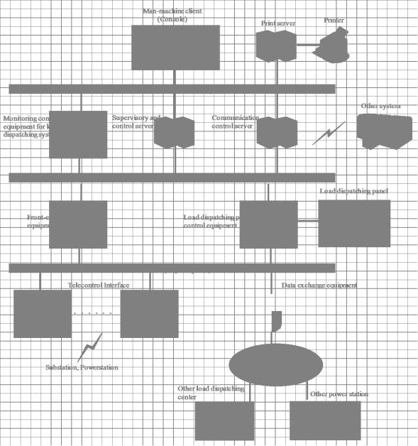
Figure 22-1 System configuration example of Load dispatch center
2. Hydropower plant
The cases when recorders are required are as follows.
(1)This configuration diagram show a general principal diagram for the control, supervision and protection system which is installed a central control room of the hydropower plant. (for example)
52
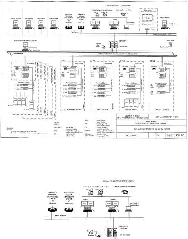
Figure 22-2 Example of installation of equipment with a record (Hydropower plant 1/3)
(2)This figure show an event and alarm of networks and hardcopy of network printers mentioned above on Figure 22-1 ( Hydropower plant 1/3).
Figure 22-3 Example of installation of equipment for record (Printer) (Hydropower plant 2/3)
53
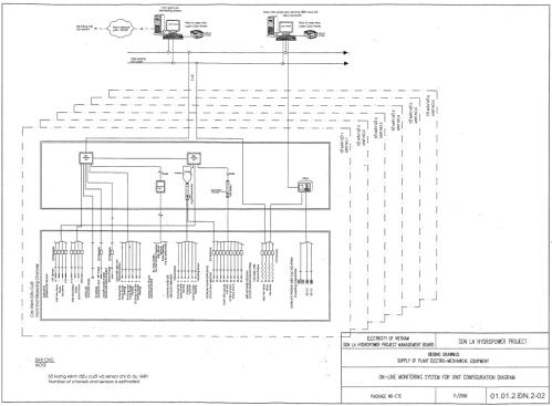
(3) This figure shows an on-line monitoring system for unit configuration diagram.
Figure 22-4 Example of installation of equipment for record (Monitoring system) (Hydropower plant 3/3)
3. Thermal Power Plant
The cases when recorders are required are as follows.
(1) Items required by law QCVN22/2009
NOX and SO2 However, dust recorders are not equipped because of accuracy and traceability.
(2) Items require on security
Items specified in the technical regulation Vol.2 electronic data may be possible ,however, measures to be taken can not be tampered with)
54