

Chapter 14 Hydrogen Generation Station
Article 375.
(Nothing)
Article 376. Check of equipment condition
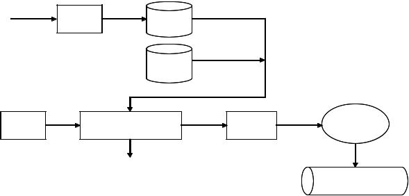
Each component of electrolytic hydrogen production system isdifferent depending on the type of the electrolytic hydrogen production system.For example, electrolytic hydrogen production system is composed of the following and its process flow diagram is shown in Figure 376-1.
-Water purifier
-Feed water storage tank
-Aqueous solution of potassium hydroxide (KOH) mixing tank
-Direct current (DC) Power supply
-Hydrogen generation unit (Electrolysis module (cell), Electrolyte circulation, Hydrogen gas
-dryer/purifier)
-Compressor
-Hydrogen storage tank (reservoir, receiver)
Row water |
Water |
Hifh Purity |
|
Hifh Purity |
water |
Feed water |
water |
||
|
Prifier |
|
|
|
|
|
|
|
|
|
|
|
|
Electrolyte solution |
|
|
|
Hifh Purity |
|
Power |
Power Electrolysis module (cell) |
Hydrogen Hydrogen gas |
Hydrogen |
Compressor |
supply |
Electrolyte circulation |
dryer/purifier |
|
|
|
|
Hifh Purity
Hydrogen
Oxygen
Hydrogen storage tank
Figure 376-1 An Example of process flow diagram of electrolytic hydrogen production system
Present condition of electrolytic hydrogen production system should be checked for safety and reliable operation before and during operation. Also, normal operating values and allowable operating ranges of each component of electrolytic hydrogen production system which may be specified by manufacturer should be confirmed prior to operation and their operational status should be monitored
and maintained within the allowable ranges during operation.henW associated alarm devices are activated, operators of the electrolytic hydrogen production system should take corrective actions according to the manufacturer’s manuals and instructions.
372
The operational status to be checked is listed below, but not limited to, because these differentare depending on the type of the electrolytic hydrogen production system.Thus, it is necessary to refer to the manufacturer’s manuals and instructions.
-Voltage and current of electrolysis module
-Pressure of hydrogen and oxygen at electrolysis module
-Liquid level at feed water storage tank and aqueous solution of KOH mixing tank
-Pressure difference between hydrogen and oxygen systems
-Temperature of electrolyte and air in dryers
-Purity of produced hydrogen and oxygen
-Pressure of hydrogen storage tank
-Purity of feed water
For reference, a related standard isISO 22734-1:2008 (Hydrogen generators using water electrolysis process - Part 1: Industrial and commercial applications) which defines the construction, safety and performance requirements of packaged or factory matched hydrogen gas generation appliances, herein referred to as hydrogen generators, using electrochemical reactions to electrolyse water to produce hydrogen and oxygen gas; however, this standard is intended to be used for certification purposes.
Article 377. Protective devices
Protective devices of each electrolytic hydrogen production system aredifferent depending on the type of the electrolytic hydrogen production systemFor. example, electrolytic hydrogen production system is equipped with the following protective devices.
-Molded case circuit breaker for power supply and motors
-Pressure detecting device and controller of hydrogen and oxygen at electrolysis module
-Hydrogen detection device and controller
It should be ensured that there is not abnormal statusof protective devices and alarm devices of electrolytic hydrogen production system before operation according to the manufacturer’s manuals and instructions.
When the electrolytic hydrogen production system is tripped during operation, operators of the system should rush to the system within 15 minutes after the tripAlso,. the system should not be restarted before ensuring the following:
-Causes of the trip are clarified.
-Necessary service or maintenance is completed.
-The system is ready to operate.
-The surrounding area is clear and staff are safely positioned or removed from the area.
-Tags and locks are removed by the same person who attached them.
-It is notified that the service or maintenance has been completed and the system is ready to operate.
-Safety procedures based on the manufacturer’s instructions are taken.
For reference, a relateddocument is IGC 15/06 (Gaseous hydrogen stations) by European Industrial Gases Association (EIGA), which is prepared for theguidance of designers and operators of gaseous
373
hydrogen stations and reflects the best practices currently availableand covers gaseous hydrogen, compression, purification, filling into containers and storage installations but production.
Article 378. Safety valve
Pressure circuit of electrolytic hydrogen production system is generally protected by safety valves and
the safety valve is normally placed close to a piece of equipment being protected in order to limit pressure drop. For example, the safety valve is installed on the following location:
-After each stage of a compressor unit (to protect the compressor unit from excessive pressure)
-Hydrogen storage tank (to protect the hydrogen storage tank from excessive pressure)
-After a pressure regulator (to protect equipment from the pressure regulator failure)
A set pressure of thesafety valve is set lower than the maximum allowable working pressure of a pressure vessel to protect the pressure vesselSince. the safetyvalve is an important component for safe operation ofthe system, periodic evaluations are required to confirm proper operation of this valve.
Thus the safety valve should be evaluated by testing and adjusted during maintenance according to the manufacturer’s instructions. As a result, operational characteristics such as the popping (opening) and closing (reseating) pressure must be complied withthe manufacturer’s instructions andapplicable standard requirement.
External condition of the safety valve is checked by visual inspection and functioning test of the safety valve consists of applying pressure to the safety valve to determine the popping (opening) and closing (reseating) pressure and a practical valve test is usually bench testing because a controlled environment can be obtained.
The following documents are referred to asguidance for an effective pressure relief valve inspection and maintenance.
-ANSI/API 510-2006 Pressure Vessel Inspection Code: Maintenance Inspection, Rating,Repair, and Alteration *1
-API Recommended Practice (RP) 576-2009 Inspection of Pressure-Relieving Devices
Note:
*1: This code covers the pressure relief devices. ANSI: American National Standards Institute API: American Petroleum Institute
Also, atmospheric discharge or discharge pipesfrom the safety valve should notterminate at a location where a possibility of accumulation of hydrogen or hazard to personnel can occur.
Article 379. A pre-purge and post-purge
Pieces of equipment and piping from an electrolysis module to a hydrogen storage tankreservoir,( receiver) of electrolytic hydrogen production system are filled with hydrogen gas during operation, but start-up of a new piece of them and a piece of them after maintenance work are filled with air, and hydrogen is flammable in air (flammability limits: 4% to 75% by volume).
374
Thus a pre-purge and post-purge should be performed with designated inert gases such as nitrogen to prevent a possibility of hydrogen explosion according to the manufacturer’s manuals and instructions.
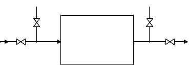
For example, a flow of pre-purge of a piece of equipment of electrolytic hydrogen production system is the following and valves installation shown in Figure 379-1.
-Close isolation valves (1, 2) of a piece of equipment.
-Purge air from a purge inlet valve (3) of the piece of equipment.
-Connect nitrogen supply to the purge inlet valve (3).
-Open the purge inlet valve (3) and a vent valve (4) of the piece of equipment.
-Pressurize the piece of equipment with nitrogen at least a half of a design pressure.
-Operate the piece of equipment at least ten minutes after setting sufficient purge flow.
- Shut down the piece of equipment after oxygen of the purge flow is less than 1% for minimum period of two minutes.
- Close the purge and vent valves (3, 4) and disconnect nitrogen supply
|
3 |
4 |
1 |
A piece of |
2 |
|
equipment |
|
Figure 379-1 An Example of valves installation
For reference, a related documentis IGC 122/00 (Environmental impacts of hydrogen plants) by EIGA, which is relevant for sites which produce hydrogen by electrolysis or chemical processes and covers principal impacts and impacts due to compression, desulphurising, reforming, maintenance and storage.; however, this standard concentrates on environmental impacts of hydrogen.
Article 380. Ventilation of the inside of a vessel
When inside check of vessels of electrolytic hydrogen production system is performed, the following items should be taken before or during work except as otherwise provided by Article 100 of national technical regulation on electric safety (QCVN 01:2008/BCT).
-Post-purge of the vessel was performed before work.
-Forced or natural adequate ventilation in the inside of vessel is performing during work.
-Oxygen concentration in the inside of vessel is not less than 19.5% by volume during work. *1
-Oxygen concentration in the inside of vessel is monitored continuously during work
-Oxygen monitors will alarm at 19.5% oxygen(An. advance warning will give enough time to avoid risk to oxygen deficiencybecause health effects of early stage are difficult to sense in general.)
-Oxygen monitors should be calibrated correctly (according to the instruction manual) in the proper period.
375