- •Table of Contents
- •List of Tables
- •List of Figures
- •List of Photos
- •Abbreviation
- •Chapter 1 Organizational Structure and Duties
- •Chapter 2 Acceptance of Equipment and Plants for putting in Operation
- •Chapter 3 Personnel Preparation
- •Chapter 4 Plan for Repair of Equipment, Plant and Construction
- •Chapter 5 Safety Technology
- •Chapter 6 Fire Prevention Equipment
- •Chapter 1 Plan
- •Chapter 1 General Provisions
- •Chapter 2 Civil Works and Mechanical Equipment for Civil Works
- •Section 1 Civil Works
- •Section 2 Check of Civil Works' Condition
- •Section 3 Mechanical Equipment for Civil Works
- •Chapter 3 Management of Water Sources in Powerhouses, Assurance of Meteorology and Hydrology
- •Section 1 Water Regulation
- •Section 2 Environment in Reservoir
- •Section 3 Hydro-Meteorological Activities
- •Chapter 4 Hydraulic Turbine / Generator
- •Chapter 1 General Provisions
- •Chapter 2 Fuel Transportation and Supply
- •Chapter 3 Pulverized Coal Processing
- •Chapter 4 Boiler and its Auxiliary
- •Chapter 5 Steam Turbine and its Auxiliary
- •Chapter 6 Unit-type of Thermal Power Plants
- •Chapter 7 Gas Turbine and its Auxiliary
- •Chapter 8 Diesel Generator
- •Chapter 9 Automation and Thermo-measuring Equipment
- •Chapter 10 Water Treatment and Hydration
- •Chapter 11 Pipelines and Valves
- •Chapter 12 Auxiliaries for Thermo-mechanical Section
- •Chapter 13 Environmental Protection Facilities
- •Chapter 1 General Provision
- •Chapter 2 Generator and Synchronous Compensator
- •Chapter 3 Electric Motor
- •Chapter 5 DISTRIBUTION NETWORK
- •Chapter 6 BATTERY SYSTEM
- •Chapter 7 OVERHEAD POWER LINES (OPL)
- •Chapter 8 Power Cable Lines
- •Chapter 9 PROTECTIVE RELAY AND AUTOMATION
- •Chapter 10 Grounding Equipment
- •Chapter 11 OVER-VOLTAGE PROTECTION
- •Chapter 13 Illumination
- •Chapter 14 Hydrogen Generation Station
- •Chapter 15 Energy Oil
- •Chapter 1 LOAD DISPATCH COMMAND
- •Chapter 3 OPERATOR
- •Chapter 4 DISPATCHING AND CONTROLLING DEVICES
access, and it is uninfluential to underground installation after having securedhe accesst road to setting equipment beforehand.
Article 281. Inspection of transformer
As stipulated in Technical Regulation.
Chapter 5 DISTRIBUTION NETWORK
Article 282. General provision
For the operation of power distribution network, it must be ensured that it is operated economically and the reliable enough for safety of public and workers. Main items of the operation of distribution network are the followings.
(1)Clarification and preparation of the dispatching order and operation process.
(2)Management of the operation control records.
(3)Monitoring supply and demand condition and the maximum load current.
(4)Monitoring voltage drop, losses and blackout impact.
(5)Balance of power flow in each feeder and phase
Article 283. Exploitation distribution network
As specified in the Technical Regulations.
Article 284. Insulation facilities of Distribution Network
The facilities for lightning are lightning arrestor, ground wire and insulation gap such asstrengthening of insulator and ZnO cut out.
Table 284 Recommended places for installation of facilities for lightning
Measurements |
|
The recommended places for the installation |
|
|
|
|
|
|
|
Step Voltage Regulator |
|
|
|
Recloser |
|
Lighting Arrester |
Both Side of the submarine cable |
||
|
Tapping point of the SS |
||
|
High voltage line at every 300m |
||
|
|
||
Ground wire |
Above high voltage line |
||
|
|
||
Insulation Gap |
Strengthen insulator (Ex. double insulation) |
||
|
|
||
ZnO cut out |
|||
|
|||
|
|
||
Lightning resistant horn |
Along the main road |
||
|
|
|
|
Article 285. Prevention of the impact from high temperature objects
Refer to article 286.
335
Article 286. Operating temperature
As it mentioned in the technical standards, a hazardous note should be hanged or a fence should be built around the object that might be over 50 degrees Celsius.
The table below is themaximum temperature of the bus and the connected conductor in a cubicle. There is also raising limitation mentioned in article 87 Volume 3.
In spatial condition, if the open airtemperature is over 40C,appropriate temperature management should be done using thermo indicator posted on thebus bar and connected conductor. They shall be attached on the position that can be easily looked from the outside.
To reduce the temperature, it is useful to install compulsion ventilation and to reduce the flow current of the bus bar to shift the load to other feeder.
Table 286 Maximum permissible temperature of conductor and contact part
|
Place |
Maximum permissible Temperature |
|
[Degrees C] |
|
|
|
|
|
|
|
Bus bar and connected conductor |
105 |
|
Contact part |
Copper contact |
75 |
|
Silver contact |
105 |
Joints of terminal |
Copper and copper |
80 |
and conductor |
Between Tin solder |
85 |
|
platings |
|
|
|
|
|
Between silver platings |
105 |
In case of dew inside a wall and surface of the equipment, it is recommended to install the space heater to raise thetemperature in the cubicle. It is also effective to installdehumidifiera and desiccants materials in the cubicle.
Article 287. Protection of intrusion
To keep the safety distancebetween the equipment and tree is the effective prevention measures against the obstacles such as animals and trees. trimmingTree should be done periodically considering the branches grow.
When the target area is in a national park, follow the authority’s instructions to have the permissions.
336
Overhead line
For example:
Tree trimming range for OPL-35kV
Trimming Part
Figure 287 Safety range of OPL for tree
Check periodically to make sure:
-If trees would not touch it because of the strong wind.
-If trees would not grow to the conductor until the next patrol.
- If branches which grow over the conductor would not hang down the conductor due to the strong winds, heavy rain or snow.
-If there is not dead trees which easily fall down around the conductors.
-If protection pipes would be effective until the next patrol.
-If there is no scratch on the conductor.
-If the visibility of the conductor is not reduced.
Below table shows the general growing length of the trees.
|
Table 287 Growth rate of trees |
|
|
|
|
Tree species |
|
Growing length a year |
|
|
|
Cedar, cypress, pine |
|
Tree age 1-20 years 70cm / year |
|
Tree age 20-40 years 35 cm / year |
|
|
|
|
|
|
|
Oak |
|
60 cm / year |
|
|
|
Paulownia, Poplar |
|
80 - 90 cm / year |
|
|
|
bamboo |
|
200 cm / week |
|
|
|
Article 288. Protection of cable trough
Regarding cable troughs and ducts, drainage pump is used to pump out the water. When there are facilities with possibility of oil leakage around it, an oil detector should be installed. The pump should
be locked and the alert should be sounded if the detector found oil leakage. The below listed items should be checked in the patrol
337

-Check there is no garbage in drainage pit and pump, and confirm it operate properly once a month
-Check the function of oil detector and confirm the proper operation of lock and warning.
Drainage To prevent the oil leakage pump from the site, when oil are
detected on the surface of drainage water by leakage oil detector, lock the startup of drainage pump and output the warning signal.
Figure 288 Drainage Pump and leakage oil detectors
Article 289. Oil insulator level
As insulation oilexpands and shrinks according to itstemperature, the level of the oil surface is fluctuated. The proper management of the oillevel should be following thetemperature and level curve, but for the tank without this curve, checke thoil level of the oil level measurements, and confirm the oil level is appropriate by the level measurements.
And if there is not enough oil in the facilities, conduct the site survey related to the oil leakages, and the facilities should be stopped if the insulation are less than the minimum requirements.
Article 290. Check of heating at joints of bus-bars
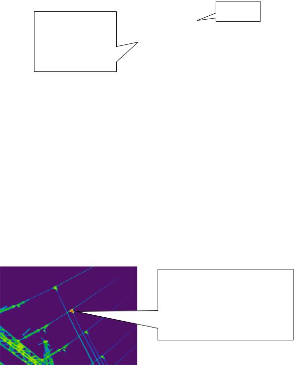
The maximum temperature of the connection point of the conductor and bus bar in a cubicle are in article 7 and article 87 in Vol.3. Ahermot label should be posted on the main part of the connection and they should be monitored during the site patrol.
Especially during the peak load season, thetemperature of the connecting point should be monitored by a infrared camera and confirm the overload conditions
Abnormal Image of overheat of connection point
As contact resistance are high compare with the permissible value. This part change re according to the inspection result infrared camera.
Figure 290 Abnormal Image of overheat of connection point (by Infrared camera)
338

Article 291. Interlock
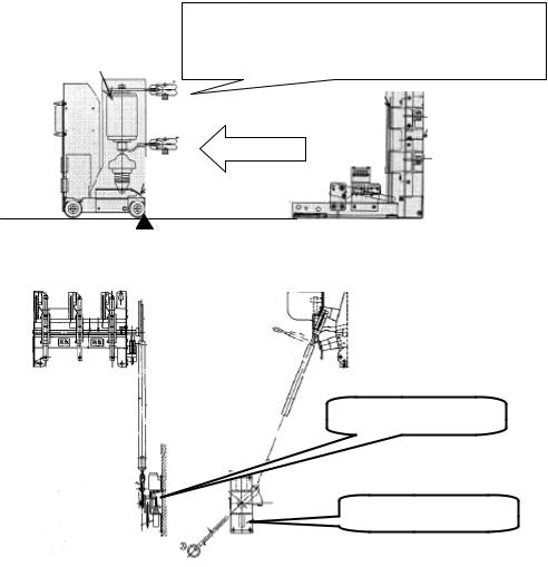
Interlocking may be necessary to ensure the correct sequence of operation of equipment, to prevent danger to personnel and to prevent damage to the equipment.
Interlocking may be achieved byboth electrical and mechanical methods. In the event of the loss of power supplies, electrical interlocking schemes shall be designed to fail safely.
|
When the CB is pulled out from the cubicle, the CB |
||
Circuit Breaker |
shall be locked at the pulled-out point, the closing |
||
operation should be |
locked.Cubicle Side |
|
|
|
|
||
Pull out
Pulled-out Point
Electrical Interlock
Mechanical Interlock
Figure 291 Example of interlock system
Article 292. Prevention of unauthorized operation Protection action error
As cubicles are supplied high voltage power, it should not be built in the place that public persons can touch them easily. The cubicles should be surrounded by fences, or built in the safe area such as inside
the electric building or the rooftop. Additionally, to lock the door is recommended to prevent the public persons from opening them easily.
Basically the cubicles should be built at least 3 m away from the outer wall. If it is notsatisfied, outer wall should be nonflammable.
339

Article 293. Ground distribution network
During the electric outage works, watchman should be dispatched to the sites, and plate indicates “DO NOT CLOSE DURING WORKING HOURS” which is locked with a key should be put heon t switchgear.
After opening the switchgears on the high voltage line, workers should check the line with an electric checker, and earth it firmly by the short earth to prevent electric shock.
Article 294. Indicator for switching position of breakers
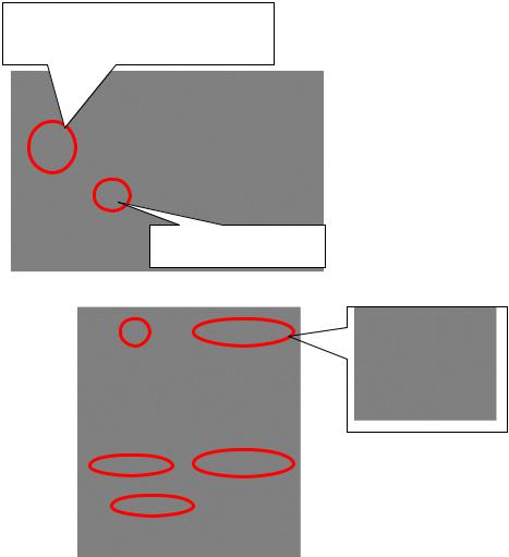
A facility shall be provided to indicate the contact position of the interrupting or isolatingequipment (including earthing switches). The method of indication in accordance with theequipment standard shall be specified by the user.
The position indicator shall provide uanambiguous indication of the actual position of the equipment primary contacts.
The device indicating the open/close position shall be easily visible to the operator.
Signal light to know the ON/OFF.
It should be installed at the place easily checked.
ON/OFF indicator on switchgear
Figure 294 Image of the indicators of switch gear
340
