
- •Table of Contents
- •List of Tables
- •List of Figures
- •List of Photos
- •Abbreviation
- •Chapter 1 Organizational Structure and Duties
- •Chapter 2 Acceptance of Equipment and Plants for putting in Operation
- •Chapter 3 Personnel Preparation
- •Chapter 4 Plan for Repair of Equipment, Plant and Construction
- •Chapter 5 Safety Technology
- •Chapter 6 Fire Prevention Equipment
- •Chapter 1 Plan
- •Chapter 1 General Provisions
- •Chapter 2 Civil Works and Mechanical Equipment for Civil Works
- •Section 1 Civil Works
- •Section 2 Check of Civil Works' Condition
- •Section 3 Mechanical Equipment for Civil Works
- •Chapter 3 Management of Water Sources in Powerhouses, Assurance of Meteorology and Hydrology
- •Section 1 Water Regulation
- •Section 2 Environment in Reservoir
- •Section 3 Hydro-Meteorological Activities
- •Chapter 4 Hydraulic Turbine / Generator
- •Chapter 1 General Provisions
- •Chapter 2 Fuel Transportation and Supply
- •Chapter 3 Pulverized Coal Processing
- •Chapter 4 Boiler and its Auxiliary
- •Chapter 5 Steam Turbine and its Auxiliary
- •Chapter 6 Unit-type of Thermal Power Plants
- •Chapter 7 Gas Turbine and its Auxiliary
- •Chapter 8 Diesel Generator
- •Chapter 9 Automation and Thermo-measuring Equipment
- •Chapter 10 Water Treatment and Hydration
- •Chapter 11 Pipelines and Valves
- •Chapter 12 Auxiliaries for Thermo-mechanical Section
- •Chapter 13 Environmental Protection Facilities
- •Chapter 1 General Provision
- •Chapter 2 Generator and Synchronous Compensator
- •Chapter 3 Electric Motor
- •Chapter 5 DISTRIBUTION NETWORK
- •Chapter 6 BATTERY SYSTEM
- •Chapter 7 OVERHEAD POWER LINES (OPL)
- •Chapter 8 Power Cable Lines
- •Chapter 9 PROTECTIVE RELAY AND AUTOMATION
- •Chapter 10 Grounding Equipment
- •Chapter 11 OVER-VOLTAGE PROTECTION
- •Chapter 13 Illumination
- •Chapter 14 Hydrogen Generation Station
- •Chapter 15 Energy Oil
- •Chapter 1 LOAD DISPATCH COMMAND
- •Chapter 3 OPERATOR
- •Chapter 4 DISPATCHING AND CONTROLLING DEVICES
Chapter 9 Automation and Thermo-measuring Equipment
Article 217. General provision
Article 217 of Technical regulation (operation and maintenance) requires check ofonditionsc of all automatic equipment and instruments.
Moreover, |
as |
stipulated |
Article |
222 of Technical regulation (operation and |
maintenance), |
disconnecting or maintaining protectors during operation is prohibited for the purpose of safety. |
|
||||
Therefore, |
if |
a measuring |
instrument |
is used for protection or control, it should be |
inspected, |
calibrated, and adjusted by the end of periodic inspection or completion inspection, and before the plant operation as stipulated Article 222 of guideline (Inspection). The power station should consider other means to eliminate all potential errors from measuring processes.
During plant operation, following are the examples of daily inspections by maintenance staff of power plant instrumentation in addition to the inspections by operating personnel.
1. Inspection by monitoring or alarming devices
Abnormal conditions of measurement and control devices are checkedyusingb the monitoring devices, such as recorders, alarm and monitoring unit, operation console panel, control panels and VDT in the central control room.
In addition, operating conditions hat occurred in the pastcould be stored in some automatic control equipment by log automatically.
2. Inspection of pneumatic automatic control equipment
Conditions of air (cleanliness, pressure), leakage from the pipes andactivation of eachpneumatic component is checked.Pneumatic automatic control equipmentis composed of mechanical components with moving parts; therefore, high frequency oftrouble may happen. The control valves are inspected carefully considering their open and plant operation condition, because some of control valves may have a direct impact on plant operation. Figure 217-1 shows an example of check point of pneumatic control equipment.
3. Inspection of electrical and electronic automatic control equipment.
It is required to avoid exposing electrical and electronic automatic control devices to high temperature and humidity as well-known.
Therefore, the control devices are installed in the roomcontrolled under the clean and appropriate temperature and humidity, such as a relay or computer room.
As described in Article 258-1,258-2 of design guideline, inspections of environmental conditions such as humidity, temperature are important.
Main inspection items inside the cabinet are as follows:
-As for power supply, it is checked that the values of voltage, current and the temperature are within allowable value.
-As for cooling fans, conditions of rotating sound, dust accumulations etc are checked.
276
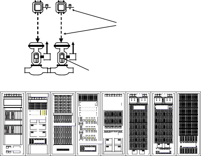
-As for input and output terminals shown in Figure 217-2, vibration and sags are checked.
-Status of the front display on the control modules shown in Figure 217-2 is checked.
Leakage from the pipes
% |
% |
Control valves openings
Figure 217-1 An example of check points of pneumatic control equipment
Noise filter |
No Fuse Breakers
Alarm display |
Terminals |
Converter power source |
Alarm |
Redundant instrumentation |
Connector |
I/O Power panel
Modem |
NFB |
Processor |
NFB |

 Processor


 Terminals


 Connector
Figure 217-2 An example of front view of electronic automatic control equipment
4. Switching the instrument
However, if na instrument for protection fails although it was inspected or repaired, following measures may be taken according to the condition.
Redundant instrumentation may be used for critical control signals for the unit, such as air flow, or steam pressure etc.
In this case, measures may be taken by the following procedure.
(1)To verify the instrument which becomes abnormal
(2)To verify the automatic switching to the normal side instrument
(3)To exclude that redundant instrumentation at this time
(4)To confirm the condition of the instrument
277
(5) To repair or replace the instrument
Following conditions may be the sign of lifetime.
1)When failure frequency becomes higher
2)When it becomes difficult to obtain replacement parts
3)Repair has become impossible technically
4)When performance is reduced and the safety can not be maintained
5)Significant increase of maintenance costs due to performance degradation
(6)To calibrate and adjust the instrument
(7)To be restored to redundant instrumentation after confirming that the deviation of the two instruments is within allowable value.
5.Shut down the equipment or the unit
If the process value cannot be measured and the equipment or the unit cannot be controlled, the equipment or the unit may be shut down by an operator according to the condition.
First priority is security and safety.
For example, if furnace draft cannot be measured and controlled, the unit should be shut down in order to prevent implosion or explosion of the boiler. Therefore, the unit should be shut down by an operator immediately, and the draft meter should be repaired or replaced, in this case.
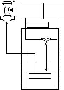
Figure 217-3 shows an example ofredundant instrumentation and Figure 217-4 shows an example of air flow failure.
However, if the failed instrument is not a critical signal for the unit, or the unit can be protected and controlled by another method, the unit does not have to be shut down.
For example, when the condenser level meter fails, however the condenser level is controlled by other level switches, the turbine and the unit do not have to be shut down.
% |
Insteument 1 |
Instument 2 |
Control unit |
compare and |
switch |
Control Logic 
Figure 217-3 An example of redundant instrumentation
278
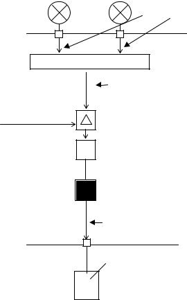
Air flow
0 100 |
0 100 |
|
|
|
Disconnection |
|
Selector |
|
|
|
Wrong value |
Flow set |
+ |
- |
|
||
|
|
|
PI Controller
FDF selector
station Auto/Hand
Wrong value is outputted in Auto mode
FDF moving blade control
Figure 217-4 An example of air flow failure
Article 218. Standby power supply
To the load as shown in Table 218, a constant voltage constant frequency (CVCF), or Uninterruptible Power Source (UPS) or redundant power supply system combining DC and AC redundant power supply using battery may be used as stabilized power supply. DC power is changed to AC power, using the thyristor type inverter.
In the case of CVCF, the inverters are controlled so that the same frequency and phase is availableas
the power supply. When a failure occurs in the inverter, power to the load is switched from the inverter to the power supply of commercial frequency automatically without interruption.
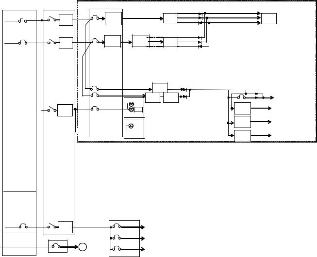
Figure 218-1 shows an example of CVCF system and circuit, Figure 218-2shows redundant system of DC and AC power supply at the control unit.
As for voltage dips and shortinterruptions, IEC61000-4-11 is referred. However, according to IEC60038, hardware of control device should operate in the voltage of 10% deviation from the rated value, as described in Article 258-1, Article 258-2 of design guideline.
279
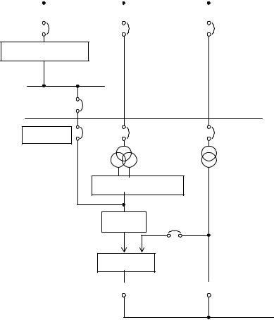
Table 218 Examples of loads requiring stable power supply
Device |
|
Processors or functions |
|
State at the outage |
||||
|
(in the case without measures) |
|||||||
|
|
|
|
|
|
|
||
|
|
|
|
|
|
|
|
|
1. Automatic control device |
- Boiler automatic control |
- Operation mode is switches to |
||||||
|
|
|
manual operation from |
|||||
|
|
|
|
device |
||||
|
|
|
|
automatic operation mode. |
||||
|
|
|
- Automatic load control |
|||||
|
|
|
- Operation terminal is locked |
|||||
|
|
|
|
equipment |
||||
|
|
|
|
at the same time. |
||||
|
|
|
|
|
|
|
||
|
|
|
|
|
|
|
|
|
2. Automatic burner control |
|
|
|
|
- The operation of solenoid |
|||
device |
- Burner control logic |
valve using multiple coils will |
||||||
|
|
|
|
|
|
|
be locked in position. |
|
|
|
|
|
|
|
|
|
|
3. Computer |
- Computer central processing |
- Computer processing is |
||||||
|
|
|
|
unit |
suspended at the time of power |
|||
|
|
|
- |
External storage device |
failure |
|||
|
|
|
- |
Process I / O device |
- Data is saved, and remains |
|||
|
|
|
- Peripheral typewriter, CRT, |
within predetermined period of |
||||
|
|
|
time in the core memory |
|||||
|
|
|
etc. |
|||||
|
|
|
|
|
||||
|
|
|
|
|
|
|
|
|
|
|
|
|
|
|
|
|
|
|
|
|
|
|
|
|
|
|
Charger machine
DC control center
CVCF |
52R |
|
52BL |
DC72B |
|
|
|
Back up |
|
|
Bypass |
|
Rectifying circuit |
||
|
Normal |
|
|
|
Inverter |
52B |
|
Alternating
switch
 52LM
52LM  52BM
52BM
Output
Figure 218-1 An example of power supply using CVCF
280
AC Power supply
DC Power supply
DC Power panel DC Power supply
AC Power supply
Noisefilterpanel |
Power entry panel |
|
|
Noise |
Noise |
AC/DC |
|
filter |
Converter |
||
filter |
|||
|
|
Noise |
Noise |
DC/AC |
AC/DC |
filter |
filter |
INV |
Converter |
I/O Power
AC/DC |
|
DC/AC |
AC/DC |
|
Converter |
|
AC/DC |
Noise filter
Cooling fans


 Cooling fans
Noise |
|
Buffer relay power |
filter |
|
|
|
|
Solenoid valve |
|
|
Solenoid valve |
|
|
|
|
Outlet |
|
DC |
Module |


 I/O Power
CRT back up power
Noise |
Temperature |
|
filter |
||
transducer power |
||
|
Noise |
Transmitter |
filter |
power |
Noise |
Pneumatic |
filter |
transducer power |
|
Figure 218-2 An example of redundant system of DC and AC power supply
Article 219. Insulation resistance of power and instrumentation cables
The insulation of electric wires and cables is deteriorated by mechanical, chemical and electrical factors. Therefore, insulation resistance of power and instrumentation cables should be measured to prevent electric failures and damage to human bodies and to secure accurate measurement in the case
of control cables.
The values of insulation resistance are required in the Article 242 of the Vol.2 of technical regulation. However, these values are minimumrequirement; therefore, the value of insulation resistance recommended to be much higher than these values and higher thethanvalue the manufacture recommends.
1. Deterioration of insulation
In general, the lifetime of electric wires and cables is approximately ranged from 15 to 30 years according to the condition.
Following factors deteriorate insulation resistance.
281
(1)Electrical factors (Such as overvoltage or overcurrent)
(2)Inundation to the wire and cable (Causing deterioration physical / electrical as a result)
(3)Mechanical factors (impact, compression, bending, twisting, tensile, vibration, etc.)
(4)Thermal factors (Lowering of low-temperature properties, due to high temperature)
(5)Chemical factors (Electrical degradation due to chemical degradation and physical properties tree oil, due to chemicals)
(6)Salt deposition, ozone and ultraviolet light (Lowering insulation performance)
(7)Damage by small animals (such as rats and termites )
(8)Deterioration caused by microorganisms such as mold
(9)Poor construction work (terminal and the connection process, the installation process, etc.).
Moreover, combination of the above (1) to (9) may also promote the degradation of electric wires and cables.
2.Measurement of insulation resistance
(1)Applied voltage for measurement
Applied voltage for measurement of the insulation resistance is selected according to the voltage of the relevant electric circuit in order to protect equipment.
Measurement voltage is referred to the inspection guideline Article 149. In addition, voltage of 25 to 50V is used for explosion proof equipment and telephone lines, 100or 125V is used for control equipment.
(2) Procedure for measurement
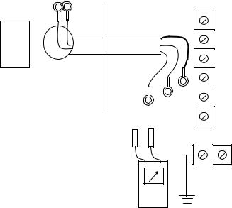
Article 149 of inspectionguideline is referred. The following are examples of procedures in detail.
1) |
Preparation |
- |
To check that the wirings to be tested are not charged |
- |
The insulation resistance tester which is described in (1) is prepared. |
- |
Transceivers or mobile phones to contact with the personnel in the field side are prepared. |
- |
To remove the connection at both the field side and panel side terminals |
- |
Wirings of the field side were disconnected from the terminal covered with vinyl tape,and |
|
remain insulated.. |
2) |
Test |
Insulation resistance is measured by theinsulation resistance tester whiledisconnecting the terminals of the equipment side. Insulation resistance is measured between following terminals.
-(1) and (2): between conductor wires
-(1) and (4), (2) and (4): between the conductor wire and the ground
-(1) and (3), (2) and (3): between the conductor wire and the shield
-(3) and (4): between the shield and the ground
282
Panel
Shield
Field
(3)
(1) (2)
Grounding terminal
(4)
Tester
Figure 219 An example of insulation resistance measurement
In addition, after measurement, discharging charges in the cable to the ground is necessary. After the discharging, cables are connected to terminals.
3)Result
a.Measurement data should be recorded and monitored for long period
b.If the insulation resistance is below the allowable value, following measures are taken..
-To dry from time to time
-To use a space heater
-To clean the equipment
-To prevent water penetration at outdoor equipment
Article 220.
(Nothing)
Article 221.
(Nothing)
Article 222. Working mode of protection, measurement system
The meaning ofthe Article 222 of the technical regulationis "Do not disconnect ordo maintain protectors during operation for the purpose of safety”.
"Protectors" means "all protectors" used in power stations or factories, not limited in a certain process value such as electricity.
Needless to say, disconnecting protectors causes disasters such as fires, or explosions, or destruction of facilities due to high pressure, high electric current, high temperature etc.
283

Moreover, repairing or calibrating online may cause not only loss ofprotection but also disaster by wrong activation of control unit.
As described in Article 244 of design guideline, control can be considered as a part of protection as follows:
|
|
|
|
Area of machine destruction |
|
|
|||
|
|
|
|
|
|
|
|
|
Heavy-fault alarms |
|
|
|
|
Heavy-fault alarms area |
|
||||
Allowable limit |
|
|
|
|
|
|
|
|
(Protection) |
|
|
|
|
|
|
|
|||
|
|
|
Light-fault alarms area |
||||||
|
|
|
|
|
Light-fault alarms |
||||
Alarm activation value |
|
|
|
|
|
|
|
||
|
|
|
|
|
|
|
(Operation) |
||
|
|
|
|
|
|
|
|||
|
|
|
|
|
|
|
|
|
|
|
|
|
|
Normal area (Automatic control) |
|
|
|||
Rated value or target value |
|
|
|
|
|
|
|
||
|
|
|
|
|
|
|
|||
Figure 222-1 |
Concept of operation, control, protection |
||||||||
In addition, Figure 217-4 shows an example of online calibrating, and air flow meter during operation has this kind of risk. If virtual high value is outputted to the controller during calibration due to no usage of the redundant meter or forgetting to switch to the redundant system, excessive fuel to the real
air flow is supplied to the boiler. This excessive fuel may cause explosion at the furnace.
However, each machine can have one or more operating modes determined by the type of machine and its application. When a hazardous condition can result from a mode selection, an unauthorized and/or inadvertent mode selection should be prevented by suitable means. (For example key operated switch and access code are used.)
Article 223. Information archive
The meaning of the rticleA 223 of the technical regulationis “operation of protectors must be recorded and analyzed for the purpose of safety in all cases, especially in the case that a protector does not operate over the set value”.
Items of records are required to contain following items.
1.Items of operating protectors
2.Operating time
3.Operating value
4.Operating conditions
As for analysis of electrical failures in the power system, a power plant is recommended to be equipped with an automatic oscilloscope because the waveform of voltage and current, conditions of switchgears and activation of protection devices can be recorded.
The operation of protectors may be alarmed to an operator, and also recorded to the log as contact signals.
284
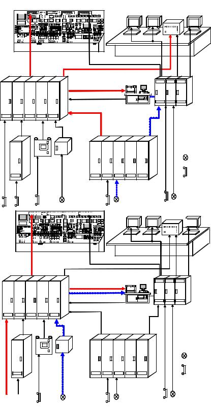
Therefore, as stipulated Article 258 of design guideline, the function of SCADA (Alarm management, trend analysis and reports) may be utilized because operating time and analog value is necessary in order to analyze. Figure 223 shows examples of signal flows.
The reason why a protector does not operate over the set value may be assumed as follows:
-The process value cannot be detected by the instrument of a protector.
-Working mode of a protector is not correct.
-The logic of the protection circuit is not correct.
-In the case of temporally signals, holding time or output time is not adequate.
-In the case of using digital processors, calculation period is not adequate.
-The set value of the protector is not correct.
-A protector is disconnected.
-Failure of a processor or instrument
During analysis, these points and operating condition of the unit may be considered.
285
Panels for |
alarms |
Operator desk
VDT |
|
|
Automatic |
|
|
|
controller |
|
|
|
Transmitter |
|
Panels |
Transducer |
|
|
in the |
Contact |
||
Panels |
|||
field |
detector |
||
|
 Interlock
panels
Operator desk

 VDT
VDT
Panels for
alarms
Computer
|
|
Automatic |
|
|
|
controller |
|
|
|
Transmitter |
|
Panels |
Transducer |
|
|
in the |
Contact |
||
Panels |
|||
field |
detector |
||
|
 Interlock
panels
Figure 223 Examples of signal flow
286
