

4. Feeding water quality is suddenly bad in comparison with standard.
It must be stopped boiler because there is possiblethat steam turbine blade and boiler tubes inside are damaged. Reasons why feeding water quality is suddenly bad are shown as follows ;
(1)Condenser tube leak (seawater)
(2)Defects in condensate demineralizer
(3) Defects in chemical dosing equipment etc. 5. Dust precipitators of coal-fired boiler are broken.
It must be stopped boiler because there is a possibilithaty gas emission form boiler can not meet environmental standard in Vietnam.
6.Some protection equipment, automatic and remote control equipment and indicators, meters are broken.
It must be stopped boiler because power plant staffs can not confirmed operation status of boiler.
Chapter 5 Steam Turbine and its Auxiliary
Article 162. General provision
It must be paid attention to following items when operating steam turbine. 1. Safe operation of main equipment and auxiliaries
It must be paid attention to following provisions to ensure safe operation of main equipment and auxiliaries.
(1)Appropriate operation of main equipment and auxiliaries
1)It must be operated main equipment and auxiliaries according to procedures developed by each power plant.
2)It must be confirmed outlet pressure, temperature and flow etc. of main equipment and auxiliaries meet acceptable value.
3)It must be conducted daily patrol and inspection according to procedures developed by each power plant.
4)It must be maintained main equipment and auxiliaries properly when detecting defects in them.
(2)Prevention of human error
1)It must be operated each equipment according to procedures developed by each power plant.
2)It must be conducted daily patrol and inspection according to procedures developed by each power plant.
3)It must be increased communication between operation group and maintenance group when inspecting of main equipment and auxiliaries.
4)It must be stay in close contact with staff in control room when operating or inspecting of main equipment and auxiliaries at each filed.
207
5)It must be understood each operation and maintenance work (e.g. opening and closing valve, turning on or off ) have impact on operation of power plant.
(3)Management of vibration
It must be paid attentio to transition of vibration of normal steam turbine operation and starting and stopping of steam turbine.
Table 162-1 Sample vibration value at alarming and stopping steam turbine
|
|
Rotor (1/100mm) |
Bearing (1/100mm) |
|
|
|
<3,000rpm> |
<3,000rpm> |
|
Stop of steam turbine |
25 |
1.25 |
||
Alarm |
Over rated speed |
12.5 |
6.2 |
|
Under rated speed |
15 |
7.5 |
||
|
||||
Normal |
Over rated speed |
Not over 7.5 |
Not over 3.8 |
|
operation |
Under rated speed |
Not over 12.5 |
Not over 6.3 |
|
(4) Prevention of crack on casing and rotor due to thermal stress
It must bepaid attention to thermal stress at staring and stopping of steam turbine as prevention means of crack. Monitoring items regarding thermal stress of steam turbine at starting are shown as follows ;
1)Differential temperature between internal and external metal of main steam stop valve
2)Differential temperature between internal and external metal of control valve
3)Differential temperature between Internal and external metal of 1st stage steam chest and re-heater steam chest
4)Restriction of temperature change rate of high and middle pressure rotor
2.Availability of rated load at heating demand
When steam turbine is operated stably, one of equipments which have an impact onvailability of rated load at heating demandis condenser. Countermeasures of keeping andupgrading performance of condenser are shown as follows;
(1) Keeping cleanliness of condenser tube
It must be kept cleanliness of condenser tube by using ball cleaning.
(2) Prevention of plugging of condenser tube
It must be prevented plugging of condenser tube due to shells etc. by operatingreversing valve of condenser (backwash).
(3) Anticorrosion of condenser tube
It must be prevented corrosion of condenser tube by condenser cathodic protection equipment.
208
(4) Reduction of power of circulating water pump
When 2 circulating water pumps are installed,electric power consumption can be decreased by operating 1 pump at low load of power plant. Moreover, electric power consumptioncan be decreased by using circulating water pump with movable vane (adjustable vane).
Article 163. Turbine control
General description of steam turbine control is shown as follows; 1. Governor setting
Turbine load (valve travel of CV) is set by governor setting duringsynchronization. Governor setting command is inputted from APC system to EHC system after APC is automatic and steam turbine load is controlled based on boiler-turbine parallel control.
2. Turbine speed control
When there is deviation between actual turbine revolution speed and rated speed,valve travel of CV
and ICV is controlled based on its deviation. And, purpose of installing this system is shown as follows;
(1)Over speed of steam turbine is serious trouble which causes damage of rotor and blade due to excessive centrifugal force. Turbine speed control system inhibits over speed of steam turbine and closing CV is given priority all the time.
(2)Turbine speed control system increases and deceases steam turbine load and adjusts steam turbine output according to network load. Governor free operation means that CV is opened and closed slightly by turbine speed control system according to fluctuation of frequency.
3.FA/PA changeover
(1)FA mode
4 CVs are opened evenly form speed up of steam turbine to regulated load (sample: 7% load) to prevent thermal deformation of steam turbine casing.
(2) PA mode
PA mode is changed fromFA mode to reduce pressure loss after steam turbine load is gotten to regulated load.
4. Automatic follow-up of load limiter
Load limiter setting is set regulatedmargin (sample: 5%) above actual load of steam turbine. When frequency of steam turbine (networkload) is gone down, actual load is increased regulated margin (sample: 5%) according to turbine speed control system. And, after actual load is gotten to regulated margin, it can be increased at regulated rate of load change (sample: 5%load /min).
5. CV opening (valve travel) control
CV command is changed over current signal and outputted to servo valve by EHC system, it is transformed control hydraulic and CV is controlledActual. CV opening is detected at liner voltage differential transformer, inputted toEHC system and current signal is amended to bring actual valve opening into line with valve opening command by CV opening control.
209
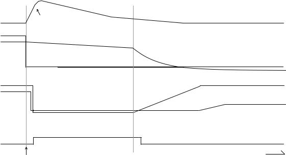
6. Power load unbalance
When electric trouble in network is caused,circuit breaker of transmission is opened and over speed of steam turbine is caused.Power load unbalance system detects unbalance between steam turbine
load and generator current and confirms that load dump is caused in network. When load dump is caused in network, power load unbalance system detects it rapidly and closes CV and ICV to prevent over speed of steam turbine before turbine speed control system is operated.
Revolution speed of steam turbine
100 |
|
Over speed |
|
|
|
102 |
100 |
|
|
High pressure exhaust pressure |
|
0 |
|
Generator load |
|
|
|
|
|
100 |
|
|
100 |
|
|
|
|
|
|
Opening of IGV |
|
0 |
|
|
|
|
|
Opening of ICV |
|
|
ON |
|
|
10ms→ |
← |
Detection of power load unbalance |
|
|
|
|
|
|
|
|
Time |
Load dump
Figure 163-1 Sample behavior of steam turbine at load dump
Article 164. Emergency governor
It must be conducted lock out test and oil trip test regarding emergency governor periodically to stop steam turbine certainly. Procedure of lock out test and oil trip test is shown as follows;
1.Confirmation before test
(1)Revolution speed of steam turbine (rated revolution speed)
(2)Indication light of “Master trip test” : lighting
(3)Indication light of “Release of lock out ” : lighting
(4)Indication light of “Lock out” : lighting out
(5)Indication light of “Oil trip ” : lighting out
(6)Indication light of “Reset ” : lighting
(7)Indication light of “During reset” : lighting out
2.Test procedure
(1)It must be pushed PB of “Lock out”.
(2)It must be confirmed that indication light of “Lock out” is lighted and “Release of lock out” is lighted out.
It must be confirmed that lock out valve is positioned lock out at steam turbine area.
210

(3)It must be pushed PB of “Oil trip”.
(4)It must be confirmed that indication light of “Trip” is lighted and “Reset” is lighted out. It must be confirmed that steam turbine is not tripped.
(5)It must be pushed PB of “Reset” continuously until indication light of “Reset ” is lighted.
(6)It must be confirmed that status following indication light.
1)Indication light of “Reset ” : lighted
2)Indication light of “During reset” : lighted out → lighted → lighted out
3)Indication light of “Trip ” : lighted out
(7)It must be pushed PB of “Release of lock out”.
(8)It must be confirmed that indication light of “Release of lock out” is lighted and “Lock out” is lighted out.
It must be confirmed that lock out valve is positioned release of lock out at steam turbine area.
Article 165. Steam stop valve and regulating valve
1. Main steam stop valve (MSV) and Re-heat stop valve (RSV)
These valves are protect equipment basically, usually opened completely (full open), andedclos urgently and steam is shut off when steam turbine has serious defect. Moreover, MSV is added full arc admission decreasing thermal stress in steam turbine with nozzlegoverning due to high temperature and pressure steam. When steam flow in steam turbineis controlled by MSV such as operation with full arc admission, it is conducted by subvalveinstalled in MSV. MSV and RSV is conducted operating test (openclose)- periodically to prevent fixing of these valve stem. Strainer is installed before MSV to prevent interfusion of foreign object.
Photo 165-1 Main stop valve |
Photo 165-2 Re-heat stop valve |
2. Regulating valve (or control valve : CV) and Intercept valve (ICV)
Regulating valve is controlled steam flow in steam turbine and operated withspeed governing device.
In some small size steam turbines, regulating valve is installed in high pressure casing. In steam turbine over 350MW, it is separated regulating valve from high pressure casing. There is a possibility
that steam in re-heat steam piping system is expanded after middle pressure steam turbine and rotary
211

frequency of rotor is increased when load of steam turbine is shut off urgently, governor is operated and regulating valve is closed. Intercept valve is started closing at 101% of rated rotary frequency and closed completely at 105% to shut off steam flow into steam turbine.
Photo 165-3 Control valve
Article 166. Check of valve
It must be conducted operating (openclose)- test regarding stop valve and regulating valves of main steam and reheat steamperiodically to stop steam turbine certainly. Procedure of operating test is shown as follows. Moreover, it must be referred to Article 167 of this guideline regarding operating test of extraction non-return valve.
1. Preparation before test
|
No. |
|
Confirmation and operation |
|
Check |
|
|
|
|
||
|
1 |
It must be decreased regulated load of power plant to conduct this test. |
|
||
|
|
|
|
|
|
|
|
It must be confirmed following items. |
|
|
|
|
2 |
- ALR operation |
|
|
|
|
- |
65 control (governor control) |
|
|
|
|
|
|
|
||
|
|
- |
Operation status of power plant is stable. |
|
|
|
3 |
It must be asked maintenance group to witness this test if necessary. |
|
|
|
|
|
|
|
||
|
4 |
It must be informed load dispatch center of commencement of this test. |
|
||
|
|
|
|
|
|
2. MSV operating (open-close) test |
|
|
|||
|
|
|
|
|
|
|
No. |
|
Confirmation and operation |
|
Check |
|
|
|
|
|
|
|
1 |
It |
must be confirmed relevant staff is distributed at control |
room |
|
|
steam turbine field. |
|
|
||
|
|
|
|
||
|
2 |
It must be confirmed left and right MSV are opened completely. |
|
|
|
|
|
|
|
||
|
3 |
It must be pushed“Left MSV” button on EHC test panel and held thi |
|
||
|
status. |
|
|
||
|
|
|
|
||
|
|
It must be confirmed following items. |
|
|
|
|
4 |
- |
Opening indicator : 0% (full close) |
|
|
|
|
- |
Fluctuation of power plant load and main steam pressure etc. |
|
|
|
|
- |
Operation status of left MSV |
|
|
|
5 |
It must be quitted hold of “Left MSV” button on EHC test panel. |
|
|
|
|
|
|
|
|
|
|
|
|
212 |
|
|

|
No. |
|
Confirmation and operation |
|
|
Check |
|
|
|
|
|
|
|
|
|
It must be confirmed following items. |
|
|
|
|
|
6 |
- |
Opening indicator : 100% (full open) |
|
|
|
|
|
- |
Fluctuation of power plant load and main steam pressure etc. |
|
|
|
|
|
- |
Operation status of left MSV |
|
|
|
|
7 |
It must be confirmed operation status of power plant. |
|
|
|
|
|
|
|
|
|
|
|
|
8 |
It |
must beconducted operating test of right MSV according |
to abo |
|
|
|
procedure. |
|
|
|
||
|
|
|
|
|
||
3. CV operating (open-close) test |
|
|
|
|||
|
|
|
|
|
|
|
|
No. |
|
Confirmation and operation |
|
|
Check |
|
|
|
|
|
|
|
|
1 |
It must be operated following item. |
|
|
|
|
|
- AFR : “Usage” → ”Cancel” |
|
|
|
||
|
|
|
|
|
||
|
2 |
It must be pushed “Load limiter Increasing” to upper limit (100%). |
|
|
||
|
|
|
|
|
|
|
|
3 |
It |
must be confirmed relevant staff is distributed at |
control |
room |
|
|
steam turbine field. |
|
|
|
||
|
|
|
|
|
||
|
4 |
It must be confirmed opening of CV. |
|
|
|
|
|
|
|
|
|||
|
5 |
It must be pushed “CV-1” button on EHC test panel and held this status. |
|
|||
|
|
|
|
|
||
|
6 |
It must be confirmed CV-1 is closed and other CV are opened. |
|
|
||
|
|
|
|
|
|
|
|
|
It must be confirmed following items regarding CV-1. |
|
|
|
|
|
7 |
- |
Opening indicator : 0% (full close) |
|
|
|
|
|
- |
Fluctuation of power plant load and main steam pressure etc. |
|
|
|
|
|
- Operation status of CV |
|
|
|
|
|
8 |
It must be quitted hold of “CV-1” button on EHC test panel. |
|
|
||
|
|
|
|
|
||
|
9 |
It must be confirmed CV-1 is opened and other CV are closed. |
|
|
||
|
|
|
|
|
|
|
|
|
It must be confirmed following items. |
|
|
|
|
|
10 |
- |
Opening indicator : recovery of opening of before test |
|
|
|
|
|
- |
Fluctuation of power plant load and main steam pressure etc. |
|
|
|
|
|
- Operation status of CV |
|
|
|
|
|
11 |
It must be confirmed operation status of power plant. |
|
|
|
|
|
|
|
|
|
|
|
|
12 |
It |
must be conducted operating test of other CV |
according to a |
|
|
|
procedure. |
|
|
|
||
|
|
|
|
|
||
4. CRV operating (open-close) test |
|
|
|
|||
|
|
|
|
|
|
|
|
No. |
|
Confirmation and operation |
|
|
Check |
|
|
|
|
|
|
|
|
1 |
It |
must be confirmed relevant staff is distributed at |
control |
room |
|
|
steam turbine field. |
|
|
|
||
|
|
|
|
|
||
|
2 |
It must be confirmed left and right CRV are opened completely. |
|
|
||
|
|
|
|
|
||
|
3 |
It |
must be pushed“Left CRV” button on EHC test panel and held thi |
|
||
|
status. |
|
|
|
||
|
|
|
|
|
||
|
|
|
213 |
|
|
|
No. |
|
Confirmation and operation |
|
Check |
|
|
|
|
|
|
It must be confirmed following items. |
|
|
|
4 |
- |
Opening indicator : 0% (full close) |
|
|
|
- |
Fluctuation of power plant load and main steam pressure etc. |
|
|
|
- |
Operation status of left CRV |
|
|
5 |
It must be quitted hold of “Left CRV” button on EHC test panel. |
|
|
|
|
|
|
|
|
|
It must be confirmed following items. |
|
|
|
6 |
- |
Opening indicator : 100% (full open) |
|
|
|
- |
Fluctuation of power plant load and main steam pressure etc. |
|
|
|
- |
Operation status of left CRV |
|
|
7 |
It must be confirmed operation status of power plant. |
|
|
|
|
|
|
|
|
8 |
It |
must be conducted operating test of right CRV according to |
abo |
|
procedure. |
|
|
||
|
|
|
||
9 |
It must be operated following item. |
|
|
|
- AFR : “Cancel” → “Usage” |
|
|
||
|
|
|
||
10 |
It must be informed load dispatch center of completion of this test. |
|
|
|
|
|
|
|
|
Article 167. Check of operation of extraction non-return valve
It must be conducted operating (open-close) test regarding extraction non-return valve periodically to stop steam turbine certainly. Procedure of operating test is shown as follows;
1. Preparation before test
|
No. |
|
Confirmation and operation |
|
|
|
|
Check |
|
|
|
|
|
|
|||
|
1 |
It must be confirmed operation status of power plant is stable. |
|
|
|
|||
|
|
|
|
|
|
|||
|
2 |
It must be confirmed each extraction non-return valve is opened. |
|
|
|
|||
|
- |
Indication WL of “Open ” : lighting (at control room) |
|
|
|
|
||
|
|
|
|
|
|
|||
2. Extraction non-return valve operating (open-close) test |
|
|
|
|
|
|||
|
|
|
|
|
|
|
|
|
|
No. |
|
Confirmation and operation |
|
|
|
|
Check |
|
|
|
|
|
|
|
|
|
|
1 |
It |
must be confirmed relevant staff is distributed |
at |
control |
room |
|
|
|
steam turbine field. |
|
|
|
|
|
||
|
|
|
|
|
|
|
||
|
2 |
It must be confirmed each is opened completely. |
|
|
|
|
|
|
|
|
|
|
|
|
|
||
|
3 |
It |
must be pushed each“Extraction non-return valve” |
button |
on test |
|
||
|
panel and held this status. |
|
|
|
|
|
||
|
|
|
|
|
|
|
||
|
4 |
It |
must be confirmed relevant extraction nonreturn- |
valve is closed |
a |
|
||
|
control room and extraction non-return valve field. |
|
|
|
|
|
||
|
|
|
|
|
|
|
||
|
5 |
It must be quitted hold of relevant“Extraction non-return valve” button |
|
|||||
|
on test panel. |
|
|
|
|
|
||
|
|
|
|
|
|
|
||
|
6 |
It |
must be confirmed relevant extraction nonreturn- |
valve is opened |
at |
|
||
|
control room and extraction non-return valve field. |
|
|
|
|
|
||
|
|
|
|
|
|
|
||
|
7 |
It must be confirmed operation status of power plant. |
|
|
|
|
|
|
|
|
|
|
|
|
|
|
|
214

No. |
Confirmation and operation |
Check |
|
|
|
8 |
It must be conducted operating test of other extraction non-return valve |
|
according to above procedure. |
|
|
|
|
Photo 167-1 Extraction non-return valve
Article 168. Turbine oil feeding system
Steam turbine oil system is to feed lubricant oil to bearings nda very important equipment to operate steam turbine stably. This oil system is composed of following equipments.
-Pumps (Main oil pump, auxiliary oil pump, emergency oil pump and turning oil pump)
-Main oil tank
-Oil cooler
-Oil purifier
-Gas extractor (ejector) etc.
Oil feeding from oil tank is cooledby oil cooler and fed to main oil pump. Main oil pump is connected with steam turbine. Oil temperature going through bearing is increased 10 20 degree C and returned to main oil tank. Auxiliary oil pump are started automatically in case of decreasing of oil pressure and emergency oil pump driven by DC motor is installed in consideration of blackout. It must be ensured following provisions to operate oil feeding system stably.
Photo 168-1 Turbine oil feeding system
215
1. Reliable operation of turbine in every operating mode
Reliable operation of turbine in every operating modedepends on proper management of each equipment by daily patrol and inspection etc. Point to be checked at daily patrol and inspection of oil feeding system is shown as follows ;
(1)Steam turbine
1)Oil temperature after bearing
2)Oil flow
(2)Main oil tank
1)Oil level
2)Oil leakage
3)Damage and deformation
4)Peeling of painting etc.
(3)Oil cooler
1)Oil temperature
2)Oil leakage
3)Damage and corrosion etc.
(4)Oil purifier
1)Oil leakage
2)Damage and corrosion etc.
(5)Gas extractor
1)Abnormal noise
2)Vibration
3)Damage and corrosion etc.
2.Safe firefighting
It must be conducted fire fighting training by whole power plant periodically because safety firefighting and appropriate early extinction prevents spread of the fire. Point to be checked and procedure at this training in case of a fire at steam turbine oil tank are shown as follows;
(1)It must be started early extinction and informed control room of power plant rapidly when detecting a fire.
(2)It must be informed fire station and established fire fighting team by power plant staff promptly.
(3)It must be followed reader’s directions of fire fighting team before fire station arrives and followed fire station’s directions after it arrives.
(4)It must be clarified role allocation of power plant staff when establishing fire fighting team.
(5)It must be started dry chemical extinguishing system and serious fire fighting as soon as possible.
(6)It must be put on rescue suit if necessary.
216
(7)It must be prevented outflow expansion of dry chemical and oil.
1)It must be closed rainwater discharge gate
2)It must be stopped waste water pump in steam turbine building.
(8)It must be tripped power plant urgently.
(9)It must be stopped oil pump after rotary frequency of steam turbine is stopped.
(10)It must be repaired damaged parts by maintenance group.
(11)It must be confirmed outflow area of dry chemical and oil and disposed them.
3.Ability to maintain oil quality corresponding to criteria
It must be supplied lubricant oil in conformity to required oil quality to operate steam turbine stably. Because required oil quality is recommended by manufacture, it must be procured oil in conformity to it by power plant. International standard of turbine oil is ASTM D 4304, ISO 8068 and JIS K 2213. In
power plant, it must be developed specification of steam turbine lubricant oil including following provisions.
(1)Equipment name
(2)Oil feeding place
(3)Lubricant oil name
(4)Oil volume per one equipment and number of equipment
(5)Total oil volume
(6)Oil feeding procedure
(7)Oil feeding interval
(8)Oil exchange interval
4.Ability to prevent oil leakage into oil cooler (cooling water system)
It must be checked oil cooler by daily patrol and maintenance to prevent oil leakage into oil cooler. It
must be referred to paragraph 1 of this article regarding point to be checked at daily patrol and maintenance of oil cooler.
Article 169. Check of backup devices
It must be started auxiliary and emergency oil pumpsrapidly and supplied lubricant oil to bearing of steam turbine when main oil pump outlet pressure or bearing oil pressure is decreased. Therefore, it must be conducted automatic starting test of these pumpsperiodically (sample test interval: once a week). Many emergency oil pumps are driven by DC motor to stop steam turbine steadily when losing AC generator (alternator). There is a possibility that bearing of steam turbine is burnt out at loss of AC generator when pace of increasing of lubricant oil pressure is low and required oil flow is not supplied. Sample procedure of automatic starting test of these pumps is shown as follows;
217
1. |
Preparation before test |
|
|
|
|
|
|
|
|
|||
|
|
|
|
|
|
|
|
|
|
|||
|
|
No. |
|
|
|
Confirmation and operation |
|
|
Check |
|||
|
|
|
|
|
|
|
||||||
|
|
|
It must be confirmed following items regarding pump. |
|
|
|
||||||
|
|
1 |
- Power source of pump : turning on |
|
|
|
|
|
||||
|
|
|
- Automatic mode |
|
|
|
|
|
|
|||
|
|
|
|
|
|
|||||||
|
|
2 |
It must be lubricant oil pressure of steam turbine bearings. |
|
|
|||||||
|
|
- Control room : |
MPa, Steam turbine field : |
MPa |
|
|
||||||
|
|
|
|
|
||||||||
|
|
3 |
It |
must |
be |
informed |
control room |
of |
commencement |
of autom |
|
|
|
|
starting test. |
|
|
|
|
|
|
|
|||
|
|
|
|
|
|
|
|
|
|
|||
2. |
|
Automatic starting test |
|
|
|
|
|
|
|
|
||
|
|
|
|
|
|
|
|
|
|
|||
|
|
No. |
|
|
|
Confirmation and operation |
|
|
Check |
|||
|
|
|
|
|
|
|||||||
|
|
1 |
It must be confirmed test oil pressure of automatic starting. |
|
|
|||||||
|
|
|
|
|
|
|
|
|
||||
|
|
2 |
It must be closed test valve gradually. |
|
|
|
|
|
||||
|
|
|
|
|
|
|
||||||
|
|
3 |
It must be confirmed that pump is started automatically. |
|
|
|
||||||
|
|
|
|
|
|
|
|
|
|
|
|
|
|
|
4 |
It |
must |
be |
confirmed oil pressure |
of |
automatic |
starting |
and it |
|
|
|
|
acceptable value. |
|
|
|
|
|
|
||||
|
|
|
|
|
|
|
|
|
||||
|
|
|
|
|
|
|
|
|||||
|
|
5 |
It must be confirmed transmitted alarms. |
|
|
|
|
|||||
|
|
|
|
|
|
|
|
|
||||
|
|
6 |
It must be opened test valve. |
|
|
|
|
|
||||
|
|
|
|
|
||||||||
|
|
|
It must be confirmed following items regarding operation status of pump |
|
||||||||
|
|
7 |
and motor. |
|
|
|
|
|
|
|
||
|
|
- Abnormal noise |
|
|
|
|
|
|
||||
|
|
|
|
|
|
|
|
|
||||
|
|
|
- |
Vibration |
etc. |
|
|
|
|
|
|
|
|
|
|
|
|
||||||||
|
|
8 |
It must be informed control room of operation status of pump and motor. |
|
||||||||
|
|
|
|
|
|
|||||||
|
|
9 |
It must be stopped pump manually and had automatic mode. |
|
|
|||||||
|
|
|
|
|
|
|
|
|
|
|
|
|
Article 170. Operation of heat exchanger system
It must be ensured following provisions at operating heat exchanger system.
-Reliability of heating exchanger in every operating mode
-Rated feeding water temperature
-To keep rated temperature difference in each heating exchanger
It must be managedheat exchanger system properly by daily |
patrol and inspection |
and periodic |
inspection to meet above provisions. Point to be checked |
at daily patrol and |
inspectionheat of |
exchanger system is shown as follows; |
|
|
-Drain level in heat exchanger system
-Feed water quality
-Opening of drain level control valve
There is a possibility that tube leak occurredis in heat exchanger systemwhen water quality is aggravated and it is serious trouble of power plant. Sample countermeasure of tube leak in low pressure heat exchanger system is shown as follows;
218

Alarm "No.4 heater water level high"
It must be confirmed following operation status.
-Water levevel of field level gauge
-Control status of No.4 heater water level
Alarm "No.3 and 4 heater water level extreme high"
It |
be |
|
fo |
tus. |
It mustbe |
confirmednfir ed |
llowingoperation sta |
||
--NoNo.4.4Ahetaerheaterextractionsteamsteaminletinletvalvevalve: :Fulllclose
--NoNo.4.4Ahetaerheaterextractiontionsteamsteamcheckvalve:: Fulllclose
Alarm "Low pressure heater drain tank water level high"
It must be requested load dispatch center to decrease power plant load.
It must be decreased power plant load.
(Power plant load is based on manufacture recommendation.)
It must be opened No.4 heater cell drain recovery valve.
It must be changed following item regarding low pressure drain tank water level contorl.
- to low pressure heater → to condenser
It must be opened low pressure heater drain pump outlet blow valve.
ItItmustbebeoperationedoperated bypassbypassof Noof .No3 and.3 and4 heater4 heateraccordingaccordingto followingto follprowingcedureproceduremonitoringmonitoringNo.4 heaterNooutl.4 hettaercondensateoutlet condensremperature. temperatureNo.3 extraction. sterma inlet valve is closed gradually.
--NoLow.3 extractionpressure heatersteamdraininletpumpvalveoutletis closedvalvegraduallyis closed. gradually.
--LowLowpressurere heaterdraindrainpumppumpisoutletstoppedvalve. is closed gradually.
-Low pressure heater drain pump is stopped.
-No.3 and 4 heater bypass valve is opened gradually.
-No.3 and 4 heater bypass valve is opened gradually.
-No.3 heater condensater inlet valve is closed gradually.
-No.3 heater condensate inlet valve is closed gradually.
-No.4 heater condensater outlet valve is closed gradually.
-No.4 hetaer condensate outlet valve is closed gradually.
It must be closed low pressure heater drain pump outlet blow valve.
Figure 170-1 Sample countermeasure (Bypass of No.3 and 4 heater)
219

Photo 170-1 Heat exchanger system
Article 171. High-pressure heater
When high pressure heater is installed 2 systems (A (No.1) system and B (No.2) system) and one system has a trouble, power plant can be continued operating by bypassingectivedef heater. High pressure heater is composed of manytubules inside heater and there is a possibility that this tube is occurred tube leak. Sample countermeasure of tube leak in high pressureeath exchanger system is shown as follows;
220

Alarm "No.6 heater water level high"
It must be confirmed following operation status.
-Water levevel of field level gauge
-Control status of No.6 heater water level
Alarm "No.6 heater water level extreme high"
ItItmustbe confirrmed that runbacksystemisisoperated. .
-powerr plantntloadisisdecreaseddevreasedtotoregulatedloadload. . ((Regulatedegukatedloadloadisisbasedbasedononmanufacturecommendationrecommendaton.) .)
ItItmustmustbebeinformedloadloaddispatchcentercenterof ofdecreasingdecreasingof ofpowerpowerplantplan loadload. .
It must be confirmed following operation status.
It must be confirmed following operation status.
- No.6A heater extraction steam inlet valve : Full close
-No.6A hetaer extraction steam inlet valve : Full close
-No.6A heater extraction steam check valve : Full close
-No.6A hetaer extraction steam check valve : Full close
It must be opened No.6A heater cell drain recovery valve.
It must be confirmed that power plant load is decreased and operation status is stable.
It must |
be stopped high pressure heater temA sysaccording to |
It must be stopped high pressure heater A system accoring to following |
|
following procedure monitoring differential temperature of feed water |
|
procedure monitoring differential temperature of feed water and |
|
and decreasing rate of feed water temperature. |
|
decresing rate of feed water temperature. |
|
- No.6A, 7A and 8A extraction steam inlet valve is closed completely. |
|
- No.6A, 7A and 8A extraction steam inlet valve is closed completely. |
|
- 6A heater feed water inlet valve and 8A heater feed water outlet valve |
|
- 6A heater feed water inlet valve and 8A heater feed water outlet valve |
|
are closed completely. |
|
are closed completely. |
|
- It must be close following valves completely. |
|
- It must be close following valves competely. |
|
- A high pressure heater vent valve |
|
- A high pressure heater vent valve |
|
- 6A |
drain deaerator inlet valve |
- 6A heater drain deaerator inlet valve
-6A heater drain condenser inlet valve
6A heater drain condenser inlet valve
-A high pressure heaterdrain blow valve
A high drain blow valve
--88heater celll blow recovery valveisisopenedcompletely. .
--77heater celll blow recovery valve isisopenedcompleterycompletely..
--66heater celll blow recovery valve isisopenedcompleterycompletely..
--6,6,77and88celll blow recovery valve areclosedcompleterycompletely.
It must be confirmed that operation status of power plant is stable.
Figure 171-1 Sample countermeasure (Stopping of high pressure heater A (No.1) system)
221
Article 172. Check before starting up
It must be confirmed condition of protection equipment and interlockof steam turbine before starting up turbine (after repair or from shutdown condition). Because it must be stopped steam turbine safely
and steadily in case that power plant has serious trouble. Sample of alarm test and interlock test is shown as follows;
1. Alarm test |
|
|
|
|
|
|
|
|
|
|
|
|
|
|
(1) |
Purpose |
|
|
|
|
|
|
|
|
|
|
|
|
|
|
It must be confirmed that defect for control system, pressure |
and peraturetem etc. related |
||||||||||||
|
steam turbine equipment are detected and alarm system is operated normally. |
|
||||||||||||
(2) |
Unit operation status |
|
|
|
|
|
|
|
|
|
|
|
||
|
Under unit operation, under unit trip |
|
|
|
|
|
|
|
|
|||||
(3) Test procedure and point to be checked (example) |
|
|
|
|
||||||||||
|
|
|
|
|
|
|
|
|
|
|
|
|
|
|
|
Test |
|
|
Test procedure |
|
|
|
Points to be checked |
||||||
|
|
|
|
|
|
|
Operatin |
|
||||||
|
item |
|
|
|
|
|
Set value |
Indicator |
||||||
|
|
|
|
|
|
|
|
|
|
|
g value |
|||
|
|
|
|
|
|
|
|
|
|
|
|
|
|
|
|
|
1) Interlock switch for rotor |
vibrati |
|
|
|
|
|||||||
|
|
|
high is deselected. |
|
|
|
|
|
|
|
|
|
||
|
|
2) Output terminal of turbine revolution |
Turbine |
|
|
|
||||||||
|
|
|
monitoring |
switch |
|
in |
|
revolution |
|
|
|
|||
|
|
|
supervisory |
instrument panel |
is |
left |
More than |
|
|
|
||||
|
|
|
open |
and |
condition |
“turbineof |
|
|
|
|||||
|
|
|
revolution more than XXXX rpm” is |
XXX X |
|
|
Rotor |
|||||||
|
Rotor |
|
prepared. |
|
|
|
|
|
|
rpm |
|
|
||
|
vibratio |
3) |
Signal |
cable |
|
of |
rotor |
vi |
|
|
mmp-p |
vibration |
||
|
n high |
|
detector |
|
in |
turbinesupervisory |
AA/100 |
|
|
high |
||||
|
|
|
instrument panel is unfixed. |
|
|
|
|
|
||||||
|
|
4) Output |
from test signal generator |
mmp-p |
|
|
|
|||||||
|
|
|
connected to above unfixed terminal |
|
|
|
||||||||
|
|
|
block 3) and imitation signa |
+ AA/100 |
|
|
|
|||||||
|
|
|
inputted. |
|
|
|
|
|
|
- AA/100 |
|
|
|
|
|
|
5) Vibration value is confirmed through |
|
|
|
|
||||||||
|
|
|
recorder at alarming. |
|
|
|
|
|
|
|
|
|||
|
|
1) Valve of bearing lubricant oil pressure |
|
|
|
|
||||||||
|
Bearing |
|
switch is closed. |
|
|
|
|
|
|
|
|
|
||
|
2) Temporary blow valve is opened and |
|
|
|
|
|||||||||
|
lubrican |
|
bearing |
lubricant |
oil |
pressure |
X.XX Pa |
|
Pa |
Bearing |
||||
|
t oil |
|
decreased. |
|
|
|
|
|
|
+ A.AA |
|
lubricant oil |
||
|
pressur |
|
|
|
|
|
|
|
- A.AA |
|
|
pressure low |
||
|
3) |
Bearing |
lubricant |
oil |
pressur |
|
|
|||||||
|
e low |
|
|
|
|
|||||||||
|
|
confirmed |
by |
temporary |
press |
|
|
|
|
|||||
|
|
|
|
|
|
|
||||||||
|
|
|
gauge at alarming. |
|
|
|
|
|
|
|
|
|
||
|
|
4) Condenser vacuum pump is stoppe |
|
|
|
|
||||||||
|
Conden |
|
at going up vacuum. |
|
|
|
|
XX |
|
|
Condenser |
|||
|
5) |
Vacuum |
control |
|
valve |
is |
op |
|
|
|||||
|
ser |
|
condenser |
vacuum |
is |
|
decre |
mmHg |
|
mmHg |
vacuum |
|||
|
vacuum |
|
|
+ AA |
|
|||||||||
|
|
gradually |
and |
operating |
value |
|
|
low |
||||||
|
low |
|
- AA |
|
|
|||||||||
|
|
alarming is confirmed by vacu |
|
|
|
|||||||||
|
|
|
|
|
|
|
||||||||
|
|
|
manometer. |
|
|
|
|
|
|
|
|
|
|
|
222
(4) Evaluation criteria
It must be confirmed alarms and necessary indications are appeared normally.
2.Interlock test
(1)Trip due to condenser vacuum low
1)Purpose
It must be confirmed that main steam stop valve and reheatersteam stop valve etc. are operated normally according to steam turbine trip due to condenser vacuum low.
2) Unit operation status
Under steam turbine stopping
3)Test procedure and point to be checked (example)
a.Test procedure
No.- X and No.- Y vacuum low test valve are opened slightly, degree of vacuum of pressure switch inlet is decreased. It must be confirmed that alarm of condenser vacuum low and turbine trip.
b.Status confirmation
Point to be checked |
|
Confirmation procedure |
|
||||
|
Before test |
Check |
After test |
Check |
|||
|
|
|
|
||||
Steam turbine |
|
|
|
Reset |
|
Trip |
|
Protection |
equipmet |
No.-X |
|
- |
|
Trip |
|
test panel |
|
No.-Y |
|
- |
|
Trip |
|
|
|
|
|
|
|
Alarm |
|
|
|
|
|
|
|
mmHg |
|
Condenser vacuum |
No.-X |
|
mmHg |
|
Trip |
|
|
|
|
mmHg |
|
||||
|
|
|
|
|
|
|
|
|
|
No.-Y |
|
mmHg |
|
Trip |
|
|
|
|
|
mmHg |
|
||
|
|
|
|
|
|
|
|
emergency |
shut |
off |
h |
Pa |
|
Pa |
|
pressure |
|
|
|
|
|
||
|
|
|
|
|
|
|
|
Main steam stop valve |
|
|
Full open |
|
Full close |
|
|
Control valve |
|
|
|
% |
|
% |
|
Reheat steam stop valve |
|
|
Full open |
|
Full close |
|
|
Intercept valve |
|
|
|
% |
|
% |
|
Ventilator valve |
|
|
|
Full close |
|
Full open |
|
BFP steam shut off valve |
|
|
Full open |
|
Full close |
|
|
No.-X – extraction check valve |
|
Full open |
|
Full close |
|
||
c. Alarm confirmation
Alarm items |
|
|
Place |
Check |
Condenser vacuum low trip |
|
|
Boiler-Turbine-Generator panel |
|
Emergency shut off hydraulic pressure |
|
Boiler-Turbine-Generator panel |
|
|
low trip |
|
|
|
|
|
|
|
|
|
Condenser vacuum low |
|
|
Boiler-Turbine-Generator panel |
|
Turbine protection equipment |
detector |
|
Boiler-Turbine-Generator panel |
|
operation |
|
|
|
|
|
|
|
|
|
|
223 |
|
|
|
4) Evaluation criteria
It must be confirmed each equipment and vales etc. are operated and alarms and necessary indications are appeared normally according to interlock.
3.Auxiliaries-related interlock test
1)Purpose
It must be confirmed that automatic start test of turning oil pump, auxiliary oil pump, emergency oil pump and control oil pump.
2)Unit operation status Under unit operation
3)Test procedure and point to be checked (example) a. Test procedure
Test |
|
|
|
Test procedure |
|
|
|
|
Point to be checked |
||||||
|
|
|
|
|
|
|
|
Operatin |
|
||||||
item |
|
|
|
|
|
|
|
Set value |
Indicator |
||||||
|
|
|
|
|
|
|
|
|
|
|
|
g value |
|||
|
|
|
|
|
|
|
|
|
|
|
|
|
|
|
|
|
a |
This |
test is conducted under |
|
|
|
|
|
|||||||
|
|
rotating speed of steam turbine. |
|
|
|
|
|
“Turning oil |
|||||||
|
b Switch of turning oil pump is set |
|
|
|
|||||||||||
|
|
“Automatic position”. |
|
|
|
|
|
|
|
pump starting |
|||||
Turning |
c |
Test valve of bearing oil pressure low |
|
X.XX Pa |
|
automatically |
|||||||||
oil |
|
of |
turbine |
is |
opened |
gradually |
and |
|
+ A.AA |
Pa |
” |
||||
|
turning |
oil |
|
pump |
is |
|
|
|
“Turbine oil |
||||||
pump |
|
|
|
|
|
- A.AA |
|
||||||||
|
automatically. |
|
|
|
|
|
|
|
|
pump outlet |
|||||
|
|
|
|
|
|
|
|
|
|
|
|||||
|
d Test valve is restored, turning oil pump |
|
|
|
pressure |
||||||||||
|
|
|
|
low ” |
|||||||||||
|
|
is stopped and switch of it is set |
|
|
|
||||||||||
|
|
|
|
|
|
||||||||||
|
|
“Automatic position”. |
|
|
|
|
|
|
|
|
|||||
|
a |
Switch of auxiliary oil pump is set t |
|
|
|
“Auxiliary |
|||||||||
|
|
“Automatic position”. |
|
|
|
|
|
|
|
||||||
|
|
|
|
|
|
|
|
|
oil pump |
||||||
|
b |
Test valve of bearing oil pressure low |
|
|
|
||||||||||
|
|
|
|
starting |
|||||||||||
|
|
of |
turbine |
is |
opened |
gradually |
a |
|
|
|
|||||
Auxilia |
|
|
X.XX Pa |
|
automatically |
||||||||||
ry oil |
|
auxiliary |
oil |
|
pump |
is |
|
op |
|
+ A.AA |
Pa |
” |
|||
|
automatically. |
|
|
|
|
|
|
|
|||||||
pump |
|
|
|
|
|
|
|
|
- A.AA |
|
“Turbine oil |
||||
c |
Test |
valve is |
|
restored, |
auxiliary |
|
|
||||||||
|
|
|
|
|
pump outlet |
||||||||||
|
|
pump |
is stopped |
and |
switch of |
|
it |
|
|
|
pressure |
||||
|
|
set to “Automatic position”. |
|
|
|
|
|
|
low ” |
||||||
|
|
|
|
|
|
|
|
|
|||||||
|
a |
Switch of turning oil pump is set |
|
|
|
|
|||||||||
|
|
“Lock |
position” and |
|
switch |
|
o |
|
|
|
“Emergency |
||||
|
|
emergency |
oil |
pump |
is |
|
s |
|
|
|
|||||
|
|
|
|
|
|
oil pump |
|||||||||
|
|
“Automatic position”. |
|
|
|
|
|
|
|
||||||
|
|
|
|
|
|
|
|
|
starting |
||||||
|
b |
Test valve of bearing oil pressure low |
|
|
|
||||||||||
Emerge |
|
X.XX Pa |
|
automatically |
|||||||||||
ncy oil |
|
of |
turbine |
is |
opened |
gradually |
a |
|
+ A.AA |
Pa |
” |
||||
|
emergency |
oil |
pump |
is |
oper |
|
|||||||||
pump |
|
|
- A.AA |
|
“Turbine oil |
||||||||||
|
automatically. |
|
|
|
|
|
|
|
|
||||||
|
|
|
|
|
|
|
|
|
|
|
pump outlet |
||||
|
c |
Test valve is restored, emergency o |
|
|
|
||||||||||
|
|
|
|
pressure |
|||||||||||
|
|
pump is stopped and switch of its |
i |
|
|
low ” |
|||||||||
|
|
set to “Automatic position”. |
|
|
|
|
|
|
|
||||||
224

Test |
|
|
Test procedure |
|
|
Point to be checked |
||||||
|
|
|
|
|
Operatin |
|
||||||
item |
|
|
|
|
Set value |
Indicator |
||||||
|
|
|
|
|
|
|
|
|
g value |
|||
|
|
|
|
|
|
|
|
|
|
|
|
|
|
a Switch |
of |
control |
oil |
pump |
is |
set |
|
|
“Control oil |
||
|
|
“Automatic position”. |
|
|
|
|
|
|||||
|
|
|
|
|
|
|
pump starting |
|||||
|
b |
Test |
valve |
of |
oil |
pressure |
slow i |
|
||||
|
|
automatically |
||||||||||
Control |
|
opened gradually, pressure switch for |
X.XX Pa |
|
||||||||
|
|
” |
||||||||||
oil |
|
alarm |
is |
operated |
and control |
+ A.AA |
Pa |
|||||
|
“Turbine oil |
|||||||||||
pump |
|
pump is operated automatically. |
|
- A.AA |
|
|||||||
|
|
|
pump outlet |
|||||||||
|
c |
Test |
valve |
is |
restored, |
control |
|
|
||||
|
|
|
pressure |
|||||||||
|
|
pump is stopped |
and |
switch |
of |
it |
|
|
||||
|
|
|
|
low ” |
||||||||
|
|
set to “Automatic position”. |
|
|
|
|
||||||
|
|
|
|
|
|
|
||||||
4) Evaluation criteria
It must be confirmed each equipment is operated andalarms and necessary indications are appeared normally according to interlock.
Article 173. Prohibition of steam turbine start-up
It must be prohibited from starting up steam turbine in case that:
1. Parameters of heat and mechanical condition of turbine exceed limitation;
When steam turbine is during staring and parameters of heat and mechanical condition of turbine exceed limitation, it must be stopped steam turbine. Sample of parameters of heat and mechanical condition is shown as follows;
(1)Vibration (It must be referred to Article 162 of this guideline.)
(2)Over speed
(3)Bearing metal temperature
(4)Lubricant oil supply and return temperature
(5)Lubricant oil pressure
(6)Elongation and differential expansion
(7) Differential temperature between main steam and metal etc.
(It must be referred to paragraph 1 of Article 162 of this guideline.) 2. One of protection equipment for stopping turbine is broken;
It must be stopped steam turbine safely and stably by protection equipment. Therefore, it must not be started steam turbine in case that one of protection equipment for stoppingsteam turbine is broken. It must be referred to Article 172 of this guideline whenconducting operation test of protection equipment of steam turbine. When confirming defects in protection equipment, it must be maintained them completely. And it must be restarted steam turbine after confirming all protection equipments are in good condition.
3. Faults of speed governing system cause turbine’s over-speed with main steam and reheat steam.
It must be operated and stopped steam turbine safely and stably by speed governing system. Therefore, it must not be started steam turbine in case that speed governing system has faults. It must be referred to Article 164 of this guideline when conducting operation test ofpeeds governing system of steam
225

turbine. When confirming defects in speed governing system, it must be maintained them completely. And it must be restarted steam turbine after confirming speed governing system is in good condition.
4. One of oil pumps or interlock of oil pump is broken;
It must be operated steam turbine safely and stably by supplying lubricant oil to bearings properly by means of oil pump system. Therefore, it must not be started steam turbine in case thatne of oil pumps or interlock of oil pump is broken. It must be referred to Article 172 of this guideline when conducting operation test of oil pump system of steam turbine.When confirming defects in oil pump
system, it must be maintained them completely. And it must be restarted steam turbine after confirming oil pump system is in good condition.
5.Oil quality does not come up to standard oil quality for operation, oil temperature is outside the stipulated range;
It must be supplied lubricant oil in conformity to required oil quality to operate steam turbine safely and stably. Therefore, it must be stopped steam turbine when oil quality does not come up to standard oil quality for operation. It must be checked oil quality at periodical inspection and exchanged new oil when oil quality is deteriorated. International standard of turbine oil is ASTM D 4304, ISO 8068 and JIS K 2213 etc. It must be referred to paragraph 3 of Article 168 of this guideline in this matter.
When lubricant oil temperature is outside the stipulated range, performance of oil can not be demonstrated and operation status of steam turbine is unstable by vibration and damage in bearings. Therefore, it must be checked carefully oil temperature at daily patrol and inspectionImust. be referred to paragraph 1 of Article 168 of this guideline regarding point to be checked at daily patrol and inspection.
Article 174. Check of turbine bearings, generators
It must be paid attention to vibration value during normal steam turbine operation and starting and stopping of steam turbine because blades and bearings of steam turbine are damaged seriously when vibration value is high. Sample of Vibration value at alarming and stopping steamturbine is shown in Table 173-1.
Table 174-1 Sample vibration value at alarming and stopping steam turbine
|
|
Rotor (1/100mm) |
Bearing (1/100mm) |
|
|
|
<3,000rpm> |
<3,000rpm> |
|
Stop of steam turbine |
25 |
1.25 |
||
Alarm |
Over rated speed |
12.5 |
6.2 |
|
Under rated speed |
15 |
7.5 |
||
|
||||
Normal |
Over rated speed |
Not over 7.5 |
Not over 3.8 |
|
operation |
Under rated speed |
Not over 12.5 |
Not over 6.3 |
|
226
1. Vibration during rising of rotational frequency
Some steam turbine is passed primary and secondary critical speed. Vibration value of steam turbine at critical speed is high generally and it must be paid attention to it during rising rotational frequency. In some mechanical equipment which load per unit area of bearing is small, oil whiphenomenon is sometimes occurred. This is occurred by self-excited vibration of lubricant oil film of bearing and it is remained even rated rotational frequency. It must be managed bearing oil temperature properly at high velocity revolution zone.
2. Rubbing
There is a possibility that vibration due to rubbing is occurred during rising of rotational frequency. This is a phenomenon which occurred in mechanical equipments after assemblingshortly afterward. When high temperature steam is flowed in reheat turbine, casing of reheat turbine is transformed and vibration due ot rubbing is occurred. Vibration of low pressure steam turbine due to rubbing is sometimes occurred by changing reheat steam temperature suddenly during low power plant load. This is occurred by deformation due to sudden temperature change of low pressureinternal casing. In
case of vibration of steam turbine due to rubbing during operation,vibration amplitude is sometimes increased suddenly. In this case, there is a possibility that steam turbine is tripped after confirming alarm and taking countermeasure. Therefore, some power plants adopt interlock in consideration of increasing rate of vibration amplitude.
Article 175. Emergency stop of turbine
When steam turbine isoccurred tripping conditions, it must be stopped steam turbine urgently to protect steam turbine, auxiliary equipments and power plant staff. It must be confirmed interlock system is operated certainly. Moreover, it must not be started steam turbine until root cause of tripping
is confirmed and maintenance is completed. Point to be checked after tripping steam turbine (MFT) is shown as follows;
1.Point to be checked after tripping steam turbine (MFT)
(1)It must be confirmed that following valves are closed to prevent over speed of steam turbine.
1)Main stop valve
2)Control valve (Regulating valve)
3)Intercept valve
4)Reheat steam valve
(2)It must be confirmed BFPTs are tripped by closing high and low pressure main stop valves.
(3)It must be confirmed following pumps are started automatically and bearing lubricant oil is supplied because main oil pump can not supply lubricant oil in proportion to deceasing of rotational frequency of steam turbine.
1)Turning oil pump
2)Main oil suction pump
(4)It must be confirmed vibration during decreasing of rotational frequency of steam turbine.
(5)It must be confirmed following valves are opened to prevent damage of condenser tubes and expansion due to inflow of drain in condenser.
227
1)Condenser water curtain spray valve
2)Low pressure casing spray valve
(6)It must be confirmed following items in consideration of restarting of steam turbine.
1)Condenser vacuum
2)Gland steam pressure
It must be specifiedcriterion of judgment of vacuum destruction in regulations of power plant.
(7)It must be confirmed condensate re-circulating system is operated to protect gland steam condenser.
(8)It must be confirmed following valves are closed (stopping of extraction steam of high and low pressure heater) to prevent water induction.
1)High and low pressure heater extraction steam inlet valve
2)High and low pressure heater extraction steam check valve
(9)It must be confirmed following turning system is operated at regular intervals after tripping.
1)Main steam turbine turning system
2)BFPT turning system
(10)It must be confirmed transmitted alarms is normal and irregular alarms are transmitted.
(11)It must be confirmed condition of steam turbine and auxiliary equipments are normal by visual check.
(12)It must be re-started steam turbine after root cause of tripping steam turbine is confirmed and maintenance is completed.
Article 176. Stop of turbine
It must be reduced output or stopped steam turbineat the Owner’s judgment in consideration of status of the equipment in cases that, (After notice to the National Load Dispatch Center).
1. Stop valve of main steam or reheat steam is stuck
When conducting MSV or RSV operation (open - close) test, there is a possibility that these valves are stuck. Countermeasure in this case is shown as follows;
228
Left MSV is stuck at MSV operation test
It must be confirmed following operation status of steam turbine.
-Differential temperature between MSV internal metal and outer metal
-Differential temperature between left MSV inlet steam and right MSV
It must be decreased power plant load after informing load dispatch center.
It must be opened following valves.
-Left main steam piping drain valve
-Drain valve before and after left MSV valve
It must be re-conducted MSV operation test.
-Push button of “Left MSV test”
-Quit hold of button of “Left MSV test”
It must be stopped power plant when left MSV is continued sticking.
It must be started stopping of power plant after informing load dispatch center.
Figure 176-1 Countermeasure in case that left MSV is stuck
2. Governing valve for steam coming to turbine is stuck or valve pin is broken
When CV is closed and stuck, operation status of power plant is changed rapidly.Countermeasure in this case is shown as follows ;
229
No.1 CV is closed and stuck.
It must be confirmed operation status of power plant is changed as follows ;
-Transmitted alarms
-Deviation of generator power output : Large
-Deviation of main steam pressure : Large
-Main steam pressure : Large
-Change of operation status
-PCV is opened automatically.
-Generator power output is decreased rapidly.
-Feed water, fuel and air flow are decreased rapidly.
-Turbine bypass valve is opened automatically.
It must be stabilized operation status of power plant by“Boiler manual mode” or “Boiler follow mode”.
-Controlling main steam and reheat steam temperature
-Patrol around boiler and steam turbine
It must be discuss with maintenance group and decided countermeasure confirming operation status of power plant is stable.
Figure 176-2 Countermeasure in case that No.1 CV is stuck
3. Faults in speed governor are occurred (Fluctuation of CV)
When speed governor has a breakdown and operation of CV is fluctuated, operation status of power plant is changed rapidly. Countermeasure in this case is shown as follows ;
230
No.1 CV is fluctuated.
It must be confirmed operation status of power plant is changed as follows ;
-Transmitted alarms
-Deviation of main steam pressure : Large
-Main steam pressure : Large
-Change of operation status
-Generator power output is fluctuated.
-PCV is opened automatically.
-Main steam pressure feed water flow, fuel flow and air flow are decreased rapidly.
-Main and reheat steam temperature are fluctuated
-Furnace draft is fluctuated.
It must be stabilized operation status of power plant by “Boiler manual mode”.
Root cause of fluctuation of CV is confirmed by following operation status.
-Opening-closing motion of governor in terms of governor opening command is defective.
It must be changed operation mode from“Boiler manual mode” to “Boiler follow” and controlled generator power output and stabilized operation status of boiler.
Figure 176-3 Countermeasure in case that operation of CV is fluctuated
4.Faults on the auxiliaries, diagram, tubes of boiler and so on occur, and such faults cannot be fixed while turbine is in operation
When tube leak of boiler is conducted, operation status of power plant is changed.Countermeasure in this case is shown as follows;
231
Tube leak of boiler is conducted
It must be confirmed operation status of power plant is changed as follows ;
-Transmitted alarms
-Deviation of main steam pressure : Large
-NOx concentration : High
-Boiler metal temperature : High
- Furnace draft : High or Low
-Change of operation status
-Feed water and fuel flow are increased because main steam pressure is deceased.
-Boiler metal temperature (water wall) is increased.
-NOx concentration is increased.
-Furnace draft is fluctuated.
It must be decreased power plant output after informing load dispatch center.
It must be confirmedroot cause of trouble (tube leak) from operation status boiler.
It must be started stopping of power plant and cooled boilerforcibly after nonsynchronization.
Figure 176-4 Co untermeasure in case of boiler tube leak
5. Faults in protection equipment which operates to stop equipment are detected
When there are some faultsin protection equipment which operates to stop equipment, here is a possibility that steam turbine is not stopped safely and stably. Therefore, it must be stopped power plant and maintained it immediately.
6.Leakage of oil tubes, main steam pipe, extraction steam pipe, reheat steam pipe, major drain pipe, feed water pipe, header, welded seams or flanges, valves and casing are detected
When detecting above defects, it must be conducted countermeasure in consideration of following provisions and damaged status and maintained damaged place.
(1)Stopping of power plant
(2)Decreasing of power plant output
(3)Bypassing of damaged system
(Damaged system is stopped and bypassed, other system is operated)
232
Article 177. Stop time of turbine
Steam turbine is rotated through inertia after it is stopped (all main valves are closed) and its rotation is stopped completely atregular intervals. After that time, it must be confirmed steam turbine is started rotating steadily by turning equipment. If not so, steam turbine can not be restarted because there is a possibility that vibration of steam turbine is occurred and bearings and blades are damaged. Therefore, when confirming that steam turbine is not rotated by turning equipment before restarting it,
it must be rotated steam turbine by turning equipment until eccentric of steamturbine rotor is met acceptable value. Point to be checked at operating turning equipment is shown as follows;
1.Point to be checked at operating turning equipment
(1)It must be operated turning oil pump or emergency oil pump to supply lubricant oil to bearings.
(2)It must be confirmed that bearing oil temperature setting is changed compared to normal operation (steam turbine is operated).
(3)It must be stopped turning equipment in case of following conditions.
1)Bearing oil temperature is higher than acceptable value.
2)Bearing metal temperature is higher than acceptable value.
(4)It can be stopped turning equipment based on manufacture instruction. However, it must be rotated steam turbine by turning equipment before restarted it.
Article 178. Operation mode of turbine
When operating steam turbine at overload, it must be referred to following sample operation procedure and monitoring items.
233

1.Sample operation procedure at overload
(1)Preparation
It must be operated following provisions as preparation of overload operation.
1)AFC -> ALR
2)Governor operation mode -> Load limiter operation mode
3)Soot blower operation mode : Automatic -> Manual
4)Rate of change of power plant load is decreased.
5)Upper limit setting of power plant load is increased.
(2)Overload operation
It must be started overload operation according to following provisions.
1)Informing load dispatch center of starting overload operation.
2)Power plant load setting is increased and actual load is got to target load.
3)Confirming that monitoring items are met acceptable value.
(please refer to paragraph 2 of this article.)
(3)Decreasing of power plant load
It must be started decreasing of power plant load according to following provisions.
1)Informing load dispatch center of decreasing of power plant load.
2)Power plant load setting is decreased and actual load is got to target load.
3)Confirming that monitoring items are met acceptable value.
(please refer to paragraph 2 of this article.)
(4)Recovery operation
It must be operated following provisions as recovery operation of overload operation.
1)Upper limit setting of power plant load is decreased.
2)Rate of change of power plant load is increased.
3)Governor operation mode -> Load limiter operation mode
4)AFC -> ALR
5)Soot blower operation mode : Automatic -> Manual
Figure 178-1 Sample operation procedure at overload
234
2. Monitoring items (Watch list) at overload operation
|
Table 178-1 Monitoring items at overload operation |
|
|
No. |
Items |
|
|
1 |
Generator power output |
|
|
2 |
Reactive power |
|
|
3 |
Main feed water rate |
|
|
4 |
Economizer inlet pressure |
|
|
5 |
Fuel flow |
|
|
6 |
NOx concentration |
|
|
7 |
SOx concentration |
|
|
8 |
Particulate concentration |
|
|
9 |
Deferential temperature between intake water and discharge water |
|
|
10 |
Vacuum of condenser |
|
|
11 |
Rotational frequency of BFPT |
|
|
12 |
Outlet pressure of BFPT |
|
|
13 |
Stator coil temperature |
|
|
14 |
Rotor coil temperature |
|
|
15 |
Traction transformer oil temperature |
|
|
Article 179. Corrosion protection
It must be taken corrosionresistance measures when boiler is put on long standby. If appropriate corrosion resistance measures are not taken, steam turbine is corroded and damaged as time go on. Consequently it must be maintained steam turbine sufficiently and paid this repair work cost when restarting it. Sample of corrosion resistance measures of steam turbine is shown as follows;
235

Table 179-1 Sample of corrosion resistance measures of steam turbine
|
|
Equipment |
Corrosion resistance measures |
||
|
|
|
|
||
|
|
Blade and casing |
- Natural seasoning |
||
Steam turbine |
Rotor and bearing |
- Application of anti-rust grease |
|||
Turning equipment |
- Application of anti-rust grease |
||||
|
|
||||
|
|
Governor |
- Application of anti-rust grease |
||
|
|
MSV |
Main body |
- Wet lay up with hydrazine |
|
|
|
Full arc equipment |
- Sealing with vinyl sheet |
||
|
|
|
|||
|
|
CV |
Main body |
- Natural seasoning |
|
Main valve |
Drive system |
- Application of anti-rust grease |
|||
|
|||||
|
|
RSV |
Main body |
- Filling with nitrogen gas |
|
|
|
ICV |
Main body |
- Natural seasoning |
|
|
|
Oil cylinder |
- Application of anti-rust oil |
||
|
|
|
|||
Lubricant oil system |
Tank |
- Application of anti-rust oil |
|||
Oil cooler |
- Natural seasoning |
||||
|
|
|
|||
Condenser |
|
Steam side |
- Natural seasoning |
||
|
Seawater side |
- Natural seasoning |
|||
|
|
|
|||
|
|
|
Main body |
- Wet lay up with hydrazine |
|
Pump |
Feed water pump |
Bearing and speed |
- Application of anti-rust grease |
||
|
|
up gear |
|||
|
|
|
|
||
|
Circulating water pump |
- Application of anti-rust grease |
|||
Article 180. Cooling water system
1. Cooling water system
Cooling water (seawater) for power plant is utilized at condenser and cooling water heat exchanger to cool steam and closed cooling water. If it is suppliednot continuously, power plant can not be operated completely. Therefore, it is very important to operate power plant as well as fuel and air, and it is necessary to operate and maintain cooling water system safely and stably. Point to be checked at daily patrol and inspection of cooling water system is shown as follows;
(1)It must be conducted daily patrol and inspection according to procedures developed by each power plant.
(2)It must be confirmed circulating water pump, rotary screen and seawater booster pump regarding following items.
1)Pump outlet pressure etc.
2)Abnormal noise, abnormal odor, vibration and leakage
3)Heating, abnormal noise and oil leakage for bearing
4)Level, change in color and leakage for lubricant oil
236

5)Seawater leakage and corrosion of piping
6)Seawater leakage and corrosion of valves
7)Corrosion and peeling for painting
Photo 180-1 Circulating water pump
Photo 180-2 Rotary screen
Photo 180-3 Seawater booster pump
(3)It must be confirmed control oil pump of circulating water pump regarding following items.
1)Pump outlet pressure etc.
2)Abnormal noise, abnormal odor, vibration and oil leakage
3)Heating, abnormal noise and oil leakage for bearing
4)Level, change in color and leakage for lubricant oil
237
5) Oil leakage and corrosion of piping
6) Oil leakage and corrosion of valves
7) Corrosion and peeling for painting
2. Chlorination equipment |
|
Chlorination equipment is utilized to keep in |
good condition ofcondenser and circulating tubesat |
power plant. Chlorination equipmentproduces |
sodium hypochlorite by electrolysis of seawater. |
Marine organism is not attached to condenser and circulating tubesby injecting sodium hypochlorite to cooling (seawater) water intake. Point to be checked of operation and daily patrol and inspection of chlorination equipment is shown as follows;
(1)Point to be checked at operation of chlorination equipment
1)It must be taken electrical safety measure when patrolling and inspecting chlorination equipment because electrolysis vessel is impressed voltage.
2)It must be taken prevention measure of short circuit.
3)It must not be used fire around chlorination equipment because hydrogen is produced by electrolysis of seawater.
4)It must be monitored residual chlorine concentration at cooling water discharge, and stopped chlorination equipment urgently when residual chlorine concentration at cooling water discharge is not met environmental standard.
(2)Point to be checked at daily patrol and inspection of chlorination equipment
1)It must be conducted daily patrol and inspection according to procedures developed by each power plant.
2)It must be confirmed seawater pump, electrolysis vessel circulating pump and electrolysis solution feed pump regarding following items.
a.Pump outlet pressure etc.
b.Abnormal noise, abnormal odor, vibration and leakage
c.Heating, abnormal noise and oil leakage for bearing
d.Level, change in color and leakage for lubricant oil
e.Leakage and corrosion of piping
f.Leakage and corrosion of valves
g.Corrosion and peeling for painting
Moreover, ball cleaning equipment andback wash reverse filtrationsystem regarding condenser are utilized.
Article 181. Operation of cooling tower
Point to be checked at daily patrol and inspection of cooling tower is shown as follows; 1. It must be confirmed vacuum of condenser.
If cooling vacuum of condenser is decreased, target cooling efficiency is not achieved. 2. It must be confirmed cooling medium temperature.
238