- •Table of Contents
- •List of Tables
- •List of Figures
- •List of Photos
- •Abbreviation
- •Chapter 1 Organizational Structure and Duties
- •Chapter 2 Acceptance of Equipment and Plants for putting in Operation
- •Chapter 3 Personnel Preparation
- •Chapter 4 Plan for Repair of Equipment, Plant and Construction
- •Chapter 5 Safety Technology
- •Chapter 6 Fire Prevention Equipment
- •Chapter 1 Plan
- •Chapter 1 General Provisions
- •Chapter 2 Civil Works and Mechanical Equipment for Civil Works
- •Section 1 Civil Works
- •Section 2 Check of Civil Works' Condition
- •Section 3 Mechanical Equipment for Civil Works
- •Chapter 3 Management of Water Sources in Powerhouses, Assurance of Meteorology and Hydrology
- •Section 1 Water Regulation
- •Section 2 Environment in Reservoir
- •Section 3 Hydro-Meteorological Activities
- •Chapter 4 Hydraulic Turbine / Generator
- •Chapter 1 General Provisions
- •Chapter 2 Fuel Transportation and Supply
- •Chapter 3 Pulverized Coal Processing
- •Chapter 4 Boiler and its Auxiliary
- •Chapter 5 Steam Turbine and its Auxiliary
- •Chapter 6 Unit-type of Thermal Power Plants
- •Chapter 7 Gas Turbine and its Auxiliary
- •Chapter 8 Diesel Generator
- •Chapter 9 Automation and Thermo-measuring Equipment
- •Chapter 10 Water Treatment and Hydration
- •Chapter 11 Pipelines and Valves
- •Chapter 12 Auxiliaries for Thermo-mechanical Section
- •Chapter 13 Environmental Protection Facilities
- •Chapter 1 General Provision
- •Chapter 2 Generator and Synchronous Compensator
- •Chapter 3 Electric Motor
- •Chapter 5 DISTRIBUTION NETWORK
- •Chapter 6 BATTERY SYSTEM
- •Chapter 7 OVERHEAD POWER LINES (OPL)
- •Chapter 8 Power Cable Lines
- •Chapter 9 PROTECTIVE RELAY AND AUTOMATION
- •Chapter 10 Grounding Equipment
- •Chapter 11 OVER-VOLTAGE PROTECTION
- •Chapter 13 Illumination
- •Chapter 14 Hydrogen Generation Station
- •Chapter 15 Energy Oil
- •Chapter 1 LOAD DISPATCH COMMAND
- •Chapter 3 OPERATOR
- •Chapter 4 DISPATCHING AND CONTROLLING DEVICES
Chapter 4 Hydraulic Turbine / Generator
Article 91. Oil Treatment (Deleted)
(Article 91 is deleted and moved to Article 382-a1 of Chapter 15 “Energy Oil” in Part 6.)
Article 92. Efficient operation
1.The turbine or pump-turbine must be, basically, operated within high-efficiency area in the efficiency curve (hill curve) according to the requirement of relevant situation for power system and hydraulic condition.
2.The power plant is generally operated by some control devices after parallel-in the power system, such as Automatic frequency control (AFC), Joint control (Automatic Load Regulator (ALR) and/or Automatic Reactive Power Regulator (AQR)), Governor free operation, Load limiting control. When they are applied, it is necessary to set them at a high effective position to get optimum power taking account of the relevant situation for power system, hydraulic condition, etc,
3.In case of pumping operation of the pumped storage power plant, a control device is applied confirming the difference between water levels of upper and lower pounds, in order to curry out an optimum pumping operation.
Article 93. Changeable operation mode
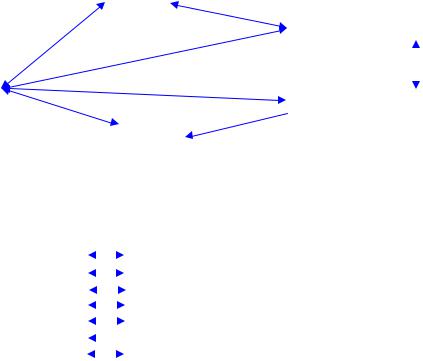
1.In case of equipping a remote control and automatic controlling system in the power plant, it is necessary to conduct the tests to confirm the changeable operation mode shown in Table 93-1, -2 and Figure 93-1 as well as a manual control to be controlled by the master switch.
2.The requirements of changeable operation mode for hydraulic power plant must be specified by the Technical Specifications of each power plant as follows, shown in Table 93-1, -2 and Figure 93-1 in general;
Table 93-1 Changeable Operation Mode
|
Mode |
Generating |
Pumping |
Synchronous |
Synchronous |
Line |
Power plant |
mode (G) |
mode (M) |
Condenser in |
condenser in |
charging |
|
|
|
|
|
Generating |
Pumping mode |
mode (CH) |
|
|
|
|
mode (SG) |
(SM) |
|
|
|
|
|
|
|
|
1) |
Generation only |
○ |
× |
× |
× |
○ |
|
|
|
|
|
|
|
2) |
Generating and |
○ |
× |
○ |
× |
○ |
|
Synchronous Condenser |
|||||
|
|
|
|
|
|
|
|
|
|
|
|
|
|
3) |
Generating, Pumping and |
○ |
○ |
○ |
○ |
○ |
|
Synchronous Condenser |
|||||
|
|
|
|
|
|
|
|
|
|
|
|
|
|
Note: 1. Power plant 2) could be changeable both modes between (G) and (SG) vice versa. 2. Power plant 3) could be changeable as following Table 93-1;
112

|
|
|
|
|
|
|
|
|
|
|
|
|
|
G |
|
|
|
|
|
|
|
|
|
|
|
|
|
|
||
|
|
|
|
|
|
|
|
|
|
|
|
|
|
|
|
|
5 |
|
|
|
|
|
|
|
|
|
||||
|
|
|
|
|
|
|
|
|
|
|
|
|
|
|
|
|
|
|
|
|
|
|
|
|
|
|
|
|
|
|
|
|
|
|
|
|
|
|
|
|
|
|
|
|
|
|
|
|
|
|
|
|
|
SG |
|
|
Standstill |
|
|||
|
|
|
|
1 |
|
|
|
|
|
|
|
|
|
|
|
|
|
|
|
|
|
|
||||||||
|
|
|
|
|
|
|
|
|
|
|
|
|
3 |
|
|
|
|
|
|
|
||||||||||
|
|
|
|
|
|
|
|
|
|
|
|
|
|
|
|
|
|
|
|
|
|
|
|
|
|
|
||||
|
|
|
|
|
|
|
|
|
|
|
|
|
|
|
|
|
|
|
|
|
|
|
|
|
|
|
|
|||
|
|
|
|
|
|
|
|
|
|
|
|
|
|
|
|
|
|
|
|
|
|
|
|
|
|
|
|
|
||
|
|
|
|
|
|
|
|
|
|
|
|
|
|
|
|
|
|
|
|
|
|
|
|
|
|
|
|
|
|
|
Standstill |
|
|
|
|
|
|
|
|
|
|
|
|
4 |
|
|
|
|
|
|
|
|
|
|
|
||||||
|
|
|
|
|
|
|
|
|
|
|
|
|
|
|
|
|
|
|
|
|
|
|
|
|
|
|
|
|||
|
|
|
|
|
|
|
|
|
|
|
|
|
|
|
SM |
|
|
CH |
|
|
||||||||||
|
|
|
|
|
|
|
|
|
|
|
|
|
|
|
|
|
|
|
|
|
|
|
|
|
|
|||||
|
|
|
|
|
|
|
|
|
|
|
|
|
|
|
|
|
|
|
|
|
||||||||||
|
|
|
|
2 |
|
|
|
|
|
|
|
|
|
|
|
|
|
|
|
|
|
|
|
|
|
|
|
|||
|
|
|
|
|
|
|
|
|
M |
|
|
|
6 |
|
|
|
|
|
|
|
|
|
||||||||
|
|
|
|
|
|
|
|
|
|
|
|
|
|
|
|
|
|
|
|
|
|
|
|
|
|
|
||||
|
|
|
|
|
|
|
|
|
|
|
|
|
|
|
|
|
|
|
|
|
|
|
|
|
||||||
|
|
|
|
|
|
|
Figure 93-1 Changeable Operation Rule |
|
|
|
|
|
|
|
||||||||||||||||
|
|
|
|
|
|
|
|
Table 93-2 Changeable Operation Rule |
|
|
|
|
|
|
|
|||||||||||||||
|
|
|
|
|
|
|
|
|
|
|
|
|
|
|
|
|
|
|
|
|
|
|
|
|
|
|
|
|
|
|
|
Rote |
|
Mode |
|
|
Direction |
|
|
|
|
|
|
|
Mode |
|
|
|
|
Note |
|||||||||||
|
1 |
|
Standstill |
|
|
|
|
|
|
|
|
G: Generating |
mode |
|
|
|
|
|
|
|
||||||||||
|
|
|
|
|
|
|
|
|
|
|
|
|
|
|
|
|
||||||||||||||
|
2 |
|
Standstill |
|
|
|
|
|
|
|
|
M: Pumping mode |
|
|
|
|
|
|
|
|||||||||||
|
|
|
|
|
|
|
|
|
|
|
|
|
|
|
|
|
||||||||||||||
|
3 |
|
Standstill |
|
|
|
|
|
|
|
|
SG: Synchronous Condenser in Generating mode |
|
|
|
|||||||||||||||
|
|
|
|
|
|
|
|
|
|
|
|
|
||||||||||||||||||
|
4 |
|
Standstill |
|
|
|
|
|
|
|
|
SM: Synchronous Condenser in Pumping mode |
|
|
|
|||||||||||||||
|
|
|
|
|
|
|
|
|
|
|
|
|
||||||||||||||||||
|
5 |
|
|
G |
|
|
|
|
|
|
|
|
SG |
|
|
|
|
|
|
|
|
|
|
|||||||
|
|
|
|
|
|
|
|
|
|
|
|
|
|
|
|
|
|
|
|
|
||||||||||
|
6 |
|
|
M |
|
|
|
|
|
|
|
|
SM |
|
|
|
|
|
|
|
|
|
|
|||||||
|
|
|
|
|
|
|
|
|
|
|
|
|
|
|
|
|
|
|
|
|
||||||||||
|
7 |
|
Standstill |
|
|
|
|
|
|
|
|
CH: line charging mode |
|
|
|
|
|
|
|
|||||||||||
|
|
|
|
|
|
|
|
|
|
|
|
|
|
|
|
|
||||||||||||||
Note: SG and SM are applied to a spinning reserve operation.
Article 94. Joint operation
1.The operation of joint control system must be carried out in order to adjust the total station active or reactive powers to the set reference value by the command remotely from the Load Dispatch Center or local control room in the power plant. Based on required active power or required voltage level and availability of the units, the control system must divide the active load or the reactive load between the units to obtain the best station efficiency.
2.The active power joint control system must be applied in order to make a balance for operation time, electric energy and output power of several units installed in the power plant.
Article 95. Protection of power plant
1.The protection of the hydraulic generator must be confirmed to carry out with the tests for all alarm and tripping circuits with interlock circuit of all electromechanical equipment in accordance with sequence diagram.
2.The tests data must be assessed statistically for maintenance & operation data, < e.g.> operating / sequence time with operating value or level for pressure oil or air, pressure oil level, measuring value of electrically, temperature & humidity, etc.,
113

Emergency Stops: (86-1)
(Electrical Heavy Faults,)
|
|
|
Inlet valve and /or |
Quick Stops: (86-2) |
|||
(Mechanical Heavy Faults) |
|
|
Wicket gates close |
|
|
||
|
|
|
|
|
|
|
|
Emergency Stops with mechanical troubles: (86-1P) (In case of pumped storage Power Plant Heavy Faults)
Opening circuit breaker  of Generator main circuit
Operating indicator or
Alarm Systems record for protection
(Main and auxiliary equipment troubles)
devices
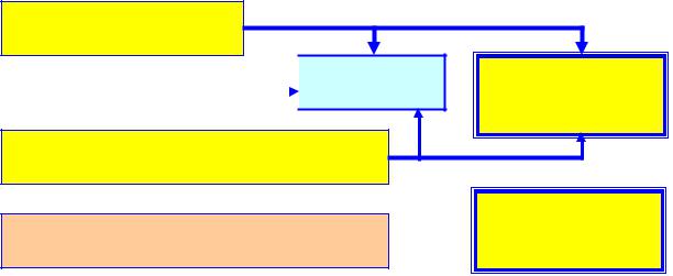
Figure 95-1 Sequence Diagram of Protection System
Article 96. Operation approval
1.The Owner must prepare the checking sheets with inspection/test plan for all equipment/devices before starting working at the site. The checking sheets of the inspection/test must be shown on the previous data with manufacturers' data for each equipment/device.
2.The results of inspection/test must be confirmed by Owner for all equipment/devices carefully, and after that, the Owner must approve to start-up the generator in a cautious manner for every location.
Article 97. Vibration
<Refer to Article 98-a1 of Guideline for Technical Regulation Vol.5.>
Article 98. Runner inspection
1.In case where works need being implemented in runner pit, it is imperative to discharge all water from penstock and/or runner pit through the drainage pipe.
(1)If an inlet valve to be installed between the penstock and spiral casing of turbine, all water in the penstock and runner pit is not necessary to discharge from penstock in general, i.e. the water in the runner pit must be drained after closing and mechanical & electrical locking the inlet valve and a draft tube gate completely.
(2)If an inlet valve to be not installed between the penstock and spiral casing of turbine, all water in the penstock and runner pit is necessary to discharge from penstock and runner pit, i.e. all water in the penstock and runner pit must be drained after closing and mechanical & electrical locking the intake gate and a draft tube gate completely.
2.The runner inspection must be carried out to check cavitation corrosion, erosion, crack, etc., together with inspection for the spiral casing, wicket gate with its sealing gaps, draft tube, painting condition of inside, etc., in accordance with an operation & maintenance manuals of each power plant.
114

3.The repairing cavitation corrosion, erosion, crack, etc., must be curried out by the suitable process, <e.g.> a welding process. However, a suitable repairing period must be decided by the result of the inspection.
Pit liner Turbine Shaft
Regulating Ring
Wicket Gate
Spiral Casing
|
|
Stay Ring |
||
Runner |
|
|||
|
|
|
|
|
|
|
|
|
|
Upper Draft
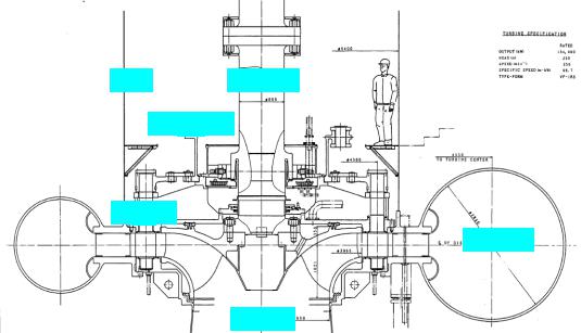
Figure 98-1 Cross-section of Francis Turbine (An example of Turbine Pit of Hydraulic Power Plant)
Article 99. Hydraulic pressure inside penstock
1.The designed value of pressure rise ratio (∆P) of the penstock for the load rejection must be specified in the Technical Specification according to the type of civil design of power plant, as follows;
(1)In case of long length penstock or high water head for turbine, a pressure rise ratio is small. <e.g.> ∆P ≤ 40%, (refer to speed rise ratio of turbine : ∆N ≥ 40%)
(2)In case of short length penstock or low water head for turbine, a pressure rise ratio is high. <e.g.> ∆P ≥ 60% (refer to speed rise ratio of turbine : ∆N ≤ 15 %)
<Refer to Item 9, in Article 92 of Guideline for Technical Regulation Vol.5.>
2.Once reducing valve is available, its automatic operation must be in line with the Technical Specifications of equipment and not cause head loss.
115
Referenced Standards and Regulations
|
Number |
Issued |
Title |
|
|
|
|
Decree |
|
2007 |
Decree on Management of Dam Safety |
No.72/2007/ND-CP |
|
|
|
|
|
|
|
Decree |
No.112/2008/ND- |
2008 |
Decree on management, protection and general exploitation |
CP |
|
|
the resources and environment of hydraulic and irrigationa |
|
|
|
reservoirs |
|
|
|
|
Circular |
No.34/2010/TT- |
2010 |
Circular regulating on the management of dam safety |
BCT |
|
|
hydropower structures |
|
|
|
|
Decision |
|
2006 |
Decision on competence to promulgate and organize |
No.285/2006/QD-TTg |
|
operation procedures of hydropower reservoirs |
|
|
|
|
|
116
