
- •Chapter 1 General Provisions
- •Chapter 3 Inspection
- •Chapter 4 In-Progress Inspection
- •Section 1 General
- •Section 2 Overhead Transmission Line
- •Section 3 Underground Transmission Line
- •Section 4 Substation Equipment
- •Chapter 5 Completion Inspection
- •Section 1 General
- •Section 3 Underground Transmission Lines
- •Chapter 6 Periodic Inspection
- •Section 1 General
- •Section 2 Overhead Transmission Line
- •Section 3 Underground Transmission Line
- •Section 4 Substation Equipment
- •Chapter 1 General Provision
- •Chapter 3 In Progress Inspection
- •Section 1 Generator/Generator-Motor
- •Section 2 Turbine/Pump-Turbine
- •Section 3 Auxiliary Equipment of Turbine/Generator
- •Section 4 Power Plant Equipment (PPE)
- •Chapter 4 Completion Inspection
- •Section 2 Periodic Inspection for Flood Control
- •Section 3 Periodic Inspection for Dam Safety
- •Section 4 Periodic Inspection for Overall Power Plants Facilities
- •Chapter 1 General Provisions
- •Chapter 2 Organization and Documentation
- •Chapter 3 Completion Inspection
- •Section 1 General Provision
- •Section 2 Mechanical Equipment
- •Section 3 Electrical Equipment
- •Chapter 4 Periodic Inspection
- •Section 1 General Provision
- •Section 2 Mechanical Equipment
- •Section 3 Electric Equipment
Chapter 4 Completion Inspection
Article 88. Inspection document (Documentation)
< The provisions of this article must refer to Article 77 in Chapter 3.>
Article 88-a1 Insulation resistance measurement
< The provisions of this article must refer to Article 79 in Chapter 3.>
Article 89. Initial operation/run
The test must be carried out by opening ofinlet valve and by a little opening of wicket gatefor the initial run soon after confirmation of starting unit, and the wicket gate and inlet valve must be closed.
(1)As the result of initial run, it must be confirmed whether there is no abnormality on contacting between rotation and static parts, noise, foul smell, bearing temperature, and vibration with axial swing.
(2)After that, the turbine generator must be operated till the rated speed gradually to proceed with the test step-by-step carefully taking temperature of each bearing into consideration.
(3)After finishing measuring and confirmation of those situations mentioned above, the machine must be stopped by braking operation, manually.
(4)In case of pure pumped storage power station which does not have water for testing in the upper poundage, the initial operation/run of pump/turbine is carried out applying a starting system of the pumping direction.
(5)If the pure pumped storage power station has a water filling-pump for penstock and upper poundage, the test is carried out for initial operation/run from a direction of the generating mode after filling water to penstock and upper poundage.
Article 90. Bearing operation/run
1.Through continuous operation of the turbine generator under each revolving speed of 25%, 50%, 75% and 100% of rated speed by opening of inlet valve and opening of wicket gate,mustit be confirmed until the bearing temperature saturate for each step taking no abnormality temperature rise, vibration, axial swing, noise, leakage water, leakage oil and bearing oil level,intoetc., consideration.
105

Each bearing metal temperatures
Temperature |
( |
|
C) |
|
0 |
Revolving speed |
(rpm) |
Cooling water inlet temperatures
Rated speed
75 %
50 %
25 %
Transit time (h-min)
Figure 90-1 Example of Bearing operation/run
2.In case of pure pumped storage power station, the bearing operation/run of pump/turbine must be executed applying a starting system of the pumping direction.
3. The temperature of each guide andthrust bearing metals and generator windgs must be measured with spare search coil installed in each guide andthrust bearing metals and generator windings.
Article 91. Automatic start and stop tests
1.Before starting this test, automatic synchronous device must be checked. Starting operation, rated load and stop operation must be controlled from generator control boardbased on the control block diagram of each operation mode.
2.Automatic start tests must be carried out to take a designated load of generator which is operated from starting to paralleling-in to the power system, automatically, bythe control of master switch (#1) and load control switch (65P).
3.The major operating time and indicator of generator must be measured and confirmed for each step in accordance with the control block diagram of each operation mode.
<e.g.>
a.Major control items of generating mode are as follows;
(a)Unit :Standstill – Preparation :Complete – By-pass valve : Open – Inlet valve: Open – Wicket gate : Open (Starting position) – Unit: Start – Field circuit breaker: On (Speed > 90%) – Excitation control : Start – Automatic synchronizer : On (Generator voltage > 90%) – Generator circuit breaker : Close – Generating Operation (load)
(b)Generating Operation (load) – Wicket gate : Close – (No load position) – Generator circuit breaker : Open – Excitation control : Stop – Field circuit breaker: Open (Generator voltage ≈ 0%)– Inlet valve: Close – By-pass valve : Close – (Speed < 50%) – Electrical brake : On – Excitation control : Start – Field circuit breaker: On – (Speed < 20%) –
106
Mechanical brake : On – Unit : Stop – (Speed < 0%) –Mechanical brake : Off –
Excitation control : Stop – Field circuit breaker: Off – Electrical brake : Off
b.Major control items of Pumping mode (by SFC) are as follows;
(a)Unit :Standstill – Preparation :Complete – Draft water depressing : Compete – Field circuit breaker: On– Excitation control : Start – SFC control : Start – Unit: Start – (Speed > 90%) –Automatic synchronizer : On (Generator voltage > 90%) – Generator circuit breaker : Close – SFC control : Stop – Draft air releasing: Complete – Priming pressure: Established – By-pass valve : Open – Inlet valve: Open – Wicket gate : Open – Pumping Operation (Optimum opening position of wicket gate).
(b)Pumping Operation – Wicket gate : Close – (No input power position) – Generator circuit breaker : Open – Excitation control : Stop – Field circuit breaker: Open (Generator voltage ≈ 0%)– Inlet valve: Close – By-pass valve : Close – (Speed < 50%) – Electrical brake : On – Excitation control : Start – Field circuit breaker: On – (Speed < 20%) – Mechanical brake : On – Unit : Stop – (Speed < 0%) –Mechanical brake : Off – Excitation control : Stop – Field circuit breaker: Off – Electrical brake : Off
4.As the result of this inspection, sequential control must be controlled without abnormality under the design valuefor operating time, operating machine and indicating devices of each step, completely.
5.In case of pumped power station, it is necessary to confirm the same test mentioned above and a changing control for each mode in accordance with changeable operation mode.
(Refer to Article 93 Changeable operation mode of Chapter 4 in Vol.4)
Article 92. Load and input rejection tests
1.The purpose of the load rejection test is to confirm shifting of the generating operation to the noload operation after load rejection withoutabnormality in penstock pressure, revolving speed and generator voltage.
2.Operation of the load rejectionis to shut down each unit duringgenerating operation at each
condition of 1/4, 2/4, 3/4 and 4/4 load. In case of the load rejection for theplural units connected to the same penstock line, it is recommended that one case is to reject the both units at same time and the other case is to reject the both units one by one with time lag. (for reference)
3.This test must be carried out at the normal, maximum and minimum head for each load condition. However, it is possible to delete theload rejection test for some condition ofthe normal and minimum head except the maximum head in accordance with discussion between Owner and Manufacture.
4.Before the load rejection test, the revolving speed, generator voltageand power factor must be kept at rated values as much as possible. And all control equipment, such as AVR, control device of over voltage, governor, etc. must be set in normal condition.
5.Each load and input rejection tests must be executed to start next test after stabilizing waterevel in the serge tank.
107
6.Each test must be conducted to measure each mater for operating andfluctuating condition of
wicket gate, penstock pressure, revolving speed, generator voltage, etc,. and measured by oscilloscope.
7.The deflecting value of upper coverof turbine must be measured at both of the noloadand load rejections.
8.Input rejection test in the pumping mode must be executed
9. As the result of this test, hydraulic |
pressure rise of penstock, |
revolving speed |
and |
generator |
|
voltage must be kept within design |
values, which must be confirmed by |
momentary |
speed |
||
variation (ΔN), momentary pressure variation (ΔP) or maximum (minimum) water pressure value |
|||||
(Pmax. Pmin.), generator voltage variation(ΔV),etc.. It must |
be confirmed |
that |
there |
is no |
|
abnormality and transferred the unit to no load operation smoothly. |
|
|
|
||
Article 93. No load no excitation test
1.During generator normal operation, by operating protection relay for no load no excitation under the sequential control, it must be confirmed whether the operation of unit controller and excitation equipment is are changed to no load no excitation mode automatically.
2.Sequential control must be confirmed of no abnormality during changing generator operation.
Article 93-a1 Characteristic test of Generator
The characteristic tests of generator must be carried out to measure the followingmajor items after finishing a phase rotation test, voltage established test, voltage adjusting test, etc,.
1.No load saturation characteristic test
(1)The generator is rotated at the rated speed.
(2)DC current of the field circuit gradually increases.
(3)Measuring the field current and terminal voltage up to 120 % of the rated voltage.
(4)The no load characteristic and balance of line voltage must be kept within the design value.
(5)The measurement of the no load saturation characteristic must be executed by the generator
voltage control of one (1) way only because the no load saturation characteristic is including hysteresis characteristic.
<i.e.> In case of no-load measurement testing of Generator, the testmust be carried out to take a characteristic curve of relationship between terminal voltage and field current of the generator during the no-load operation with the rated speed.
108
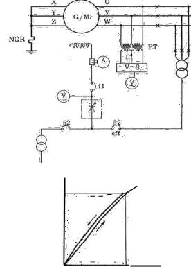
Station
Generator voltage
power
Rated voltage
(kV)
Field current
Gen main circuit
Ex. Transformer
(Vn)
If0
(A)
Figure 93-a1-1 Example of No load saturation characteristic test
2. Axial voltage measurement
The shaft current preventing device must be provided normally for all generators which are specified in the Technical Specifications.
(1)The axial voltage must be measured at the rated voltage under no load saturation characteristic test.
(2)The voltage must be measured between upper bearing and lower bearing (V1), upper bearing and earth (V2), and lower bearing and earth (V3), as follows.
(3)Axial voltage must be measured when output terminal voltage up to the rated voltage.
(4)The measured voltage must be confirmed of noabnormality comparing with normal condition.
109
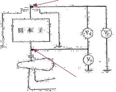
Contacting device for measuring axial voltage
|
|
|
|
|
Generator / |
|
Rotor |
||
Generator Motor |
|
|
|
|
|
|
|
|
|
|
|
|
|
|
Contacting device for measuring axial voltage
Figure 93-a1-2 Example of Axial voltage measurement
(Reference Documents)
- 2-11-11 in No.48NL/KHKT.
(Reference information: Shaft current preventing device)
1.Suitable preventing measures must be taken against burning of the bearing metal due to the shaft current.
2.Adequate insulation must be provided at the base of the upper bracket. In addition, perfect insulation must be provided for cooling water pipes, oil pipes and pressure conduits for thermometers, which may conceivably form closed circuits, if necessary. The insulation must be ensured by placing the two(2) insulators in series for each circuit. For confirming the goodness of the insulation by measuring the shaft voltage and insulation resistance, the wiring must be provided up to the suitable places. The position and construction of such insulation must be clearly indicated in the drawings.
3.Three phase short circuit test
(1)Test method is to separate between generator and bus circuit at outlet terminal of stator coil or primary side of circuit breaker.
(2)Generator side is short circuited at outside of stator coil.
(3)The generator is rotated at rated speed and DC current is charging in excitation circuit.
(4)Measuring field current and armature current reach to 100% of rated armature current. <i.e.> In case of short-circuit measurement testing of Generator, the generator bus circuitmust be
connected by the short-circuit copper bar for the threephases- line-leads/conductors of the main generator circuit. And then, the testmust be carried out to take a characteristic curve of relationship between armature current (short-circuit current) and field current of the generator.
110
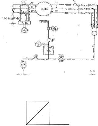
Three phases short circuit bars
Ex. Transformer
Station Power source |
Change over switch |
Open circuit location |
currentArmature A |
|
Rated current |
(Ir) |
|
Field current |
(A) |
|
|
|||
|
|
If2 |
|
Figure 93-a1-3 Example of Three phase short circuit test
(5)As the result, the values of short circuit ratio and synchronous impedance must be kept within design value.
(6)Generator constants must be confirmed in accordance with the characteristics test of generator, such as no-load open-circuit test, Three-phase short circuit test, sudden threephase short-circuit test, etc,.
Reference information:
The reactances , Xd , X‘d , X‘’d , X‘q , X’’q , are identified as following;
(a)Xd It is derived from “No-load open-circuit test and three-phase short circuit test.
(b)X‘d , It is derived from “Sudden three-phase short-circuit test. Or, itis derived from ”Applied voltage recovery test” which is a “Type test "of “Sudden three-phase open-circuit test.
(c)X‘’d , It is derived from “Sudden three-phase short-circuit test or, it is derived from ”DaltonCameron method”, or, ”Applied voltage recovery test”.
(d)X‘q , It is derived from “Low slip test”. However, It is not provided in IEC.
(e) X’’q |
It is |
derived |
from”Applied |
voltage |
test", “Daltonor-Cameron |
method”. |
However, |
it, |
normally, is |
not carriedafter-installation |
test because of demanding test for |
||
generator at site, such as, “Sudden threephase- |
short-circuit test”, and /or“Sudden three-phase |
|||||
open-circuit test” which are carried out on “Type test”.) |
|
|
||||
111
(Reference Documents)
-4 in IEEE Std 115– 1995, Test Procedure for Synchronous Machines, Dielectric and partial discharge tests
-11.1.2 in IEC 600034-2 (2007&2010), Rotating electrical machines, Part 2-1 Standard methods for
determining losses and efficiency from tests, Part-22Specific methods for determining separate losses of large machines from tests-Supplement to IEC 60034-2-1
- 2-1-9 in No.48NL/KHKT.
4.Excitation system operation test
The operation tests for excitation system must be carried out for major items as follows;
(1)Measurement of voltage adjusting range : 90R
The voltage adjusting range (90R) must be confirmed in relation between each setting location and generated voltage at the no load operation of generator with rated speed, which are kept within design value.
(2)Indicial response test :
The dynamic characteristic of voltage control must be confirmed at the operation of noloads.
<i.e.> It is input to voltage output side of stepping purse during operation condition at no-load, rated speed and rated voltage.
The result of time measurement till stability must be shortened within about 2 cycles.
(3)Test of reactive power adjusting device :
The adjusting control for reactive power must be carried out smoothly by automatic reactive power regulation (AQR).
(4)Test of generator voltage establishment :
The test of generator voltage establishment must be confirmed to establish the generator voltage smoothly by preliminarily exciting device which is operated by a speed detecting relay (#13).
Article 94. Emergency stop test (heavy electrical trouble)
1.By short circuiting the contacts of protection relay(e.g. generator differential relay, #87)for emergency stop, the sequential control of emergency stop must be checked.
2. Generator must be safely stopped complying with |
designed sequential control, i.e. generator |
circuit breaker: off, wicket gate: close, inlet |
valve: close, stopping complturbinetely, in |
accordance with sequential control correctly. |
|
Article 95. Quick stop test (heavy mechanical trouble)
1. By short circuiting the contacts ofprotection relay (e.g. hydraulic drop of pressure oil relay, #63Q3) for quick stop, the sequential control of quick stop must be checked.
2.Generator must be safely stopped complying with designed sequential control, i.e. wicket gate: close, generator circuit breaker: off, inlet valve: close, stopping turbinecompletely, in accordance with sequential control correctly.
112
3.In case of pumping mode, if the same trouble occurred as item 1, an emergency stop is executed by hydraulic drop of pressure oil relay, (#63Q3).
Article 96. Load and input tests
1.Operation of the generator and pumping must be continued until the bearing temperature saturated at rated load condition, in which the revolving speed, generator voltage, load and power factor are kept at the rated values.
2.The measuring in the test must be also continueduntil saturation for temperature of generator windings and main circuit lines (e.g. IPB, Powercable, etc.), main transformer together with vibration of turbine and generator, leakage oil and water, noise, each temperature of each cooling water and condition of auxiliary equipment
3. As the |
result, it must be confirmedof continuous rated loadand input operation without |
abnormality. |
|
(Reference Documents) |
|
-IEC 60034-4 |
(1985). Rotating electrical machines, Part 4 Amendment No.1 |
Article 97. |
Output test |
|
|
1. |
As the method of this measurement, wicket gate servomotor stroke must be changedto measure |
||
|
the operation scope and output limitation under the load conditionforeach water level |
of |
|
|
maximum, rated, minimum heads. |
|
|
2. |
During output test,the power factormust be preferable to keep the rated power factorIf. it |
is |
|
|
difficult to keep the rated power factor, a constant value of power factormust be kept. And the |
||
|
adjusting load must be carefullycontrolled only in one way, i.e. there must not be over control |
||
|
exceeding the setting value and must not control to opposite side during increasing or decreasing. |
|
|
3.During output test, the relationship between the noloadopening of wicket gate stroke and the difference water reposing device must be confirmed for testing water level (net head).
4.As the result of this test under each load operation condition, it must be confirmedwhether there is no abnormality in vibration, swing of axis and hydraulic pressure.
|
Constant discharge |
|
|
In case of output limitation |
|
|
Max. |
gate |
|
constant of wicket |
|
|
head |
|
Output (kW) |
Rated. |
|
head |
||
Min. |
||
head |
||
|
||
|
Not preferable scope |
of |
|
case |
|
|
of operation |
|
|
|
In |
|
Servomotor stroke (mm) |
|
Figure 97-1 Example of Output test
113
Article 98. Pumping operation test
1. The pumping operation must be controlled and started under the stipulated starting method without time delay of starting equipmentand stopped under the stipulated stoppingsequence control without no abnormality.
(1)The major items of the pumping starting method are as follows;
1)Thyristor starting system,
2)Back-to buck (or Synchronous) starting system,
3)Directly coupled motor (or Pony motor) starting system,
4)Damper winding-reduced voltage starting system.
Recently, the combined system of the thyristor and back-to back starting is applied to the pumping starting system for the several units of pumped storage power plant.
Each pumping starting system have a different auxiliary equipment in accordance with a purpose of the starting method, therefore, a maintenance & operation manual must be prepared for each starting system base on the manufacture’s instruction.
2.During this test, the synchronous condenser operation test must be also confirmed together with a test for the water depressing equipment without no abnormally.
Article 98-a1 Vibration measurement
1.The vibration of electrical machine must be measured at the mounting of the measuring point of the machine.
It is necessary to measure the vibration on the machine alone under properly determined test conditions without any influence from other equipment.
2.In the result of measurement, the vibration changes depending on the operation condition; therefore it must be compared with normal condition and its abnormality must be judged by the design criteria of the power plant.
3.The values of vibration are usually indicated to be 1/100 mm (0.01mm) for all (both) side of an amplitude, as follows.
Table 98-a1-1 Example of Vibration Values
Revolving speed |
Type of |
Amplitude value |
Shaft swinging |
||
(min-1) |
generator |
Upper |
Lower |
(Reference value) |
|
|
|
bracket |
bracket |
*1 |
|
Lower 400 min-1 |
Normal |
15.0 |
2.5 → 5.0 |
Within 70 ~ 80 % |
|
Umbrella |
15.0 |
10.0 |
for bearing |
||
|
|||||
|
Normal |
10.0 |
2.5 → 4.0 |
clearance, metal |
|
Over 400 min-1 |
Umbrella |
10.0 |
7.5 |
temperature: |
|
|
not over 75 oC |
||||
|
|
|
|
||
Note: *1 : The shaft swinging is measured at location of guide bearings during operating condition of rated revolving speed and rated output with in 75 oC of the bearing temperature.
114
4.Reference data of the International standard are as follows;
(1)The maximum shaft vibration as measured near the turbine and generator guide bearings is within ISO 7919-5, zone “A” (Mechanical vibration - Evaluation of machine vibration by measurements on rotating shafts), when operating at rated speed, de-excited and any load.
(2)Non rotating parts is within ISO 10816-5, zone “A” or zone boundary “A/B” (Mechanical vibration - Evaluation of machine vibration by measurements on non-rotating parts).
(3)All components of the generator must be designed, constructed and balanced to avoid undue or harmful vibrations and resonances.
<e.g.> In case of vertical machine of conventionaltype (IM8421, IEC 60034-7), machine; upper guide bearing equipped with upper bracket (UB) installed upper the rotor, lower guide bearing equipped with lower bracket (LB) installed under the rotor, and turbine guide bearing installed on turbine head cover (THC).
115
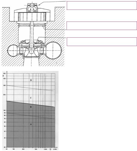
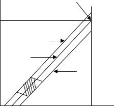
Upper guide bearing equipped with UB
Lower guide bearing equipped with LB
Turbine guide bearing installed on THC
ISO 7919-5:
a: Shaft maximum relative vibration displacement, (Smax,μm)
b: Maximum service speed, (min-1)
The vibrations on the rotating shaft of the unit must meet requirements of the ISO 7919-5, Zone A: when the unit is operated in steady state conditions.
Zone C: Fortransient regimes (start, stop, quick and emergency shut downs), the values stated must apply.
Figure 98-a1-1 Example of Vibration test
(Shaft swinging: Refer to IEEE Std 1095 -1989 15.1.2)
5.Reference faction test: Overspeed test
(1)The overspeed test is executed to examine a durable level of the bearing metals and a mechanical strength for rotating parts of turbine-generator. The level of overspeed and time are as follows in general.
116
No. |
Type of Synchronous machine |
Overspeed |
|
|
|
1 |
All synchronous machine without bel |
120 % of Max. rated revolving speed. |
|
type |
|
|
|
|
2 |
Auxiliary equipment to be connected |
If no standard, it is a runaway speed, |
|
directory to the main machine or turbine - |
however, over 120 % of Max. rated |
|
generator, generator -motor by electrically or |
revolving speed. *1 |
|
mechanically. |
|
|
|
|
3 |
In case of execution of overspeed test for all |
Testing time : 2 seconds |
|
type. |
|
|
|
|
Note: *1: If an emergency protection relay of overspeed of 115% is installed, the overspeed of generator must be examined by overspeed of 115%.
(2)It is necessary to inspect completely for all inspection area and to consider protection wall.
(3)It is necessary to confirm, during testing without vibration, noise, temperature and anosmatic smell and smoke in the machine and behavior of the oil in the bearings.
(4)After testing, it is necessary to inspect completely whole situations of all area in which the variation occurred electrically and mechanically. And it is not allowed to find any permanent deformation, some trouble for normal operation and then the armature winding must be withstood the dielectric voltage test specified in the document.
(5)The overspeed test for the salient-pole synchronous machine is normally not necessary to be executed at site except the cylindrical-rotor synchronous machine. However, it is necessary to inspect in case of assignment or in case of decision after discussion between Owner and Manufacture.
(Reference Documents)
-IEEE Std.CP65-a56 20, Standardization of Conductor Vibration Measurements
-ISO 7919-5, 2005, Mechanical vibration– Evaluation of machine vibration by measurements on rotating shafts. Part -5 Machine sets in hydraulic power generating and pumping plants.
- ISO 10816-5, 2000, Mechanical vibration – Evaluation of machine vibration by measurements on non – rotating parts. Part -5 Machine sets in hydraulic power generating and pumping plants.
-TCVN 6962 / 2001 Vibration Standard,
-2-11-11 in 48NL/KHKT,
Article 98-a2 Operating confirmation of power plant equipment
1.Though the major power plant equipment (PPE) in Section 4 has been executed to inspect / test before trial operation / run, they are finally inspected by visual check before starting and parallelin of turbine / generator to the power system .
117
Article 98-a3 Trial operation/run
< The provisions of this article must refer to Article 174 of Section 3 in Part 4>
1.After successful termination of all commissioning tests, all units must be subject to a trial run period under the Contractor’s supervision and responsibility.
2.During this period, Owner’s personal must be made fully acquainted with the operation and routine maintenance of the equipment.
3.The trial run period must be two (2) months. After satisfactory performance tests of the equipment during commissioning tests and trial run period, a Provisional Acceptance Certificate (PAC) [“Certificate of TemporaryAcceptance” ] is issued by the Representative or Owner. On the date of issue of the PAC, the guarantee period begins.
Chapter 5 |
Periodic Inspection |
Section 1 |
General |
Article 99. |
General provision |
1. Three types of periodic inspection
Three types of periodic inspections are stipulated in Technical Regulation Vol.5 as follows:
(1)Periodic Inspection for Flood Control
This periodic inspection is required for dams and spillways of hydropower plants pursuant to Article 14 of Decree No.72/2007/ND-DP, and related provisions are stipulated in Section 2 of Part 3 Chapter 5 in Technical Regulation Vol.5.
(2)Periodic Inspection for Dam Safety
This periodic inspection is required for safety of dams of hydropower plants pursuant to Article 17of Decree No.72/2007/ND-DP, and related provisions are stipulated in Section 3 of Part 3 Chapter 5 in Technical Regulation Vol.5.
(3)Periodic Inspection for Overall Power Plants Facilities
This periodic inspection is originally stipulated in Technical Regulation Vol.5 for overall hydropower facilities excluding dams and spillways which must follow the stipulation for the above two types of periodic inspections, andelatedr provisions are stipulated in Section 4 of
Part 3 Chapter 5 in Technical Regulation Vol.5.
2.Practice of periodic inspection
(1)Each type of periodic inspections is conducted by both ways of document examination and field inspection for all or some selected works. The details must refer to Section 2, Section 3 and Section 4 of this Chapter for the periodic inspection for flood control, periodic inspection for dam safety and periodic inspection for overall power plant facilities respectively.
(2)Each type of periodic inspection is conducted by a competent authority together with the plant owner and the competent authority is responsible to evaluate the result of inspections and notify
118
