

Table 26-a1-3 AC voltage test for cables rated voltage more than 30kV
(IEC60840, 62067)
Rated voltage |
Test voltage |
|
(kV r.m.s) |
||
U (kV) |
||
(phase-to-ground) |
||
|
||
110 |
128 |
|
220 |
180 |
|
500 |
320 |
2) DC voltage test of the oversheath
- Test voltage: DC voltage of 4 kV per millimeter of specified thickness of extruded oversheath shall be applied with a maximum of 10 kV DC between the underlying metallic layers and the outer electrode.
- Duration of test is 1 minute.
Section 4 Substation Equipment
Article 27. The inspection item for transformers
1. Visual Inspection
It shall be checked whether the transformer has abnormalities such as oil leakage, crack, breakage, damage, looseness at screwed parts, etc. or not.
It shall be checked whether the installation of components such as pipes, bushing, tank, valve, auxiliary systems, etc. have abnormalities or not.
Silica gel, which is used to eliminate the moisture of oilfilledtransformers, shall be checked of its color. If it was discolored in pink, silica gel shall be replaced.
2. Measurement of Insulation Performance
Insulation-resistance tests are made to determine the insulation resistance from individual windings to ground or between individual windings.
It is subject to wide variation with design, temperature, dryness, and cleanliness of the parts. When the insulation resistance falls below prescribed values, it can, in most cases, if it is of good design and has no defect, be brought up to the prescribed value by cleaning and drying the apparatus.
The significance of values of insulation-resistance tests generally requires some interpretation, depending on the design, dryness, and cleanliness of the insulation involved. If a user decides to make insulation-resistance tests, it is recommended that insulation-resistance values be measured periodically (during maintenance shutdown) and that these periodic values be plotted. Substantial variation in the plotted values of insulation resistance should be investigated for cause.
The inspection method and criteria are as below.
(1)-1 Measurement of Insulation resistance of windings: R60 (for oil-immersed type)
This measurement shall comply with the following conditions by using a 2,500V megger.
14
1)Insulation resistance for transformers lower than 150 kV shall be measured at o10C and higher, and one for transformers higher than 220 kV shall be measured at higher than 30 oC.
2)Insulation resistance for transformers 110kV and higher than 80,000 kVA or one for transformers higher than 220kV shall be measured at temperature not exceedingplus/minus
5 oC in comparison with temperature when manufacturer measured the insulation resistance. For transformers lower than 150kV and 80,000kVA, this difference of temperature shall not exceed plus/minus 10 oC.
Nevertheless, in the case that the temperature in the field is different from the one in the factory, the measurement result of the insulation resistance shall be compensated by using the coefficient K1 in Table 27-1.
Table 27-1 Coefficient K1
Difference of |
1 |
2 |
3 |
4 |
5 |
10 |
15 |
20 |
25 |
30 |
temperature [oC] |
||||||||||
Coefficient K1 |
1.04 |
1.08 |
1.13 |
1.17 |
1.22 |
1.50 |
1.84 |
2.25 |
2.75 |
3.40 |
|
|
|
|
|
|
|
|
|
|
|
If difference of temperature is not included in Table 1,27-coefficient corresponding to it shall be calculated by multiplication of each coefficient.
Ex.) Difference of temperature 9 oC is not included in Table 27-1; K9 = K5 K4= 1.22 *1.17= 1.42
3)The temperature of windings for transformers lower than 35kV is considered to be equal with the top layer of oil. On the other hand, the one for transformers higher than 35kV is considered to be equal with the temperature of phase B of primary windings calculated by the following formula.
tx = Rx/R0 (235+t0)-235
R0: the winding resistance measured at temperature t0 in the factory
Rx: the winding resistance measured at temperature tx |
|
|
|
4) The measurement |
for thetransformers higher than 110kV |
shallbe carried |
out for |
120 seconds after |
grounding the windings. If the measurement |
is repeated, |
it should be |
carried out for more than 300 seconds after grounding the windings again.
If there is no data of inspection doneby manufacturers at factories, it is possible to refer to the permissible minimum values in Table 27-2.
15
Table 27-2 Standards of the insulation resistance [MΩ]
Voltage level for primary |
|
|
Windings temperature [oC] |
|
|
||||
windings |
10 |
20 |
|
30 |
40 |
50 |
|
60 |
70 |
|
|
|
|
|
|
|
|
|
|
Lower than 35kV and lowe |
450 |
300 |
|
200 |
130 |
90 |
|
60 |
40 |
than 10,000kVA |
|
|
|||||||
|
|
|
|
|
|
|
|
|
|
Higher than 35kV and highe |
|
|
|
|
|
|
|
|
|
than 10,000kVA or higher than |
900 |
600 |
|
400 |
260 |
180 |
|
120 |
80 |
110kV independent of capacity |
|
|
|
|
|
|
|
|
|
In the case that transformer isnot fully filled with oil, measurement of windingresistance can be carried out if oil level is 150 to 200 mm from the top of transformer, and the main insulating parts are fully in the oil.
(1) - 2 Measurement of Insulation resistance of windings for Dry-type transformers
This measurement shall comply with the manufacturer’s instruction. If there isno data of inspection done by manufacturers at factories, insulation resistance shall be more than 100 MΩ.
(Japanese standard for reference).
(2)Measurement of Insulation resistance for control circuits (for oil-immersed and dry type) Insulation resistance between control circuits and the ground shall be measured by a 500V or 1,000V megger to confirm that it is more than 2 MΩ.
(3)Measurement of dielectric loss for windings (for oil-immersed type)
Measurement of dielectric loss angle (tan δ) shall be applied to the transformer of voltage 110kV and over and the transformer of voltage 35kV and over with capacity 10,000 kVA and higher. This measurement shall comply with 1), 2) and 3) inSection (1). As like R60, tan δ measured in the field shall be compared with the data of factory inspection or latest inspection. However, it is possible to refer to the permissiblemaximum value of tan δ% in Table 27-3, if there is not such data.
Table 27-3 Standards of tan δ for windings of transformers
|
|
|
|
|
|
|
|
|
|
|
|
|
(%) |
Voltage level of primary |
|
|
|
Windings temperature [oC] |
|
|
|||||||
|
windings |
|
|
10 |
20 |
|
30 |
40 |
50 |
|
60 |
70 |
|
|
|
|
|
|
|
|
|
|
|
|
|
|
|
Lower |
than |
35kV |
and |
lo |
1.2 |
1.5 |
|
2.0 |
2.6 |
3.4 |
|
4.5 |
6.0 |
than 10,000kVA |
|
|
|
|
|||||||||
|
|
|
|
|
|
|
|
|
|
|
|||
Higher |
than |
35kV |
and |
high |
|
|
|
|
|
|
|
|
|
than 10,000kVA or |
higher |
than |
0.8 |
1.0 |
|
1.3 |
1.7 |
2.3 |
|
3.0 |
4.0 |
||
110kV independent capacity |
|
|
|
|
|
|
|
|
|
|
|||
In the case that the temperature in the field is different from the one in the factory, the measurement result shall be compensated by using the coefficient K2 in Table 27-4.
16
|
Table 27-4 |
Coefficient K2 |
|
|
|
|
||||
Difference of |
|
|
|
|
|
|
|
|
|
|
temperature |
1 |
2 |
|
3 |
4 |
|
5 |
10 |
15 |
16 |
[oC] |
|
|
|
|
|
|
|
|
|
|
Coefficient K2 |
1.05 |
1.10 |
|
1.15 |
1.20 |
|
1.25 |
1.55 |
1.95 |
2.4 |
If difference of temperature is not included in above table, coefficient corresponding to it shall be calculated by multiplication of each coefficient as well60 inas PartR 1) Section (1). Since this measurement is influenced by insulating oil, it is necessary to exclude the influence in order
to evaluate the result correctly.
tan δTr = tan δMe - K3 (tan δOil2 - tan δOil1)
tan δTr |
: Actual value of tan δ for windings of transformer |
tan δMe |
: Measured value of tan δ for windings in the field |
tan δOil1: tan δ of oil in the transformer measured in the factory whichis modified to the measurement temperature.
tan δOil2: tan δ of oil in the transformer measured in the field whichis modified to the measurement temperature.
K3 : Conversion coefficient depending on structure of transformer with its value of nearly equal to the coefficient in Table 27-5.
Tan δ for oil is modified by using coefficeint K3 according to the differece of temperature.
Table 27-5 Coefficient K3
Difference of |
|
|
|
|
|
|
|
|
|
temperature |
1 |
2 |
3 |
4 |
5 |
10 |
15 |
20 |
30 |
[oC] |
|
|
|
|
|
|
|
|
|
Coefficient K3 |
1.03 |
1.06 |
1.09 |
1.12 |
1.15 |
1.31 |
1.51 |
2.0 |
2.3 |
If tan δ measured in the field is lower than 1%, it is considered as it satisfies the standards regardless of the result of the factory inspection.
(4)Measurement of dielectric loss for bushing
Dielectric loss angle (tan δ) for bushing shall be measured between the bushing head terminal and the bracket, to confirm that the measured value is within the manufacturers’ standards.
3.Measurement of Transformation Ratio (for oil-immersed and dry type)
Transformation ratio shall be checked for each tap to confirm that the difference between measured value and themanufacturers’ standards is less than 0.5%. The transformation ratio (n) shall be calculated as below by measuring secondary voltage (V2) when primary voltage (V1=100-200V; AC)
is applied.
n= V1/V2
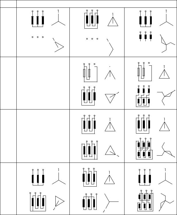
4.Vector group Test (for oil-immersed and dry type)
Polarity, wire connection and phase sequence of transformers shall be checked. For single-phase transformers, all windings shall be checked for polarity.
17
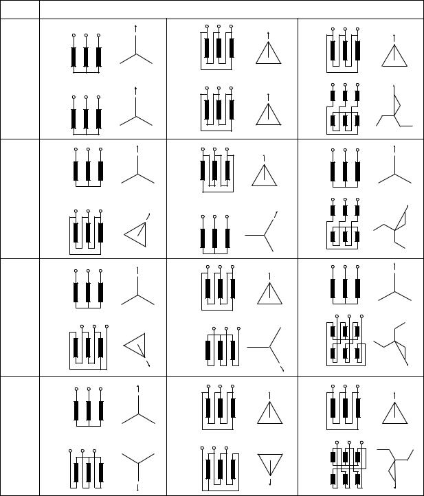
For three-phase transformers, all windings shall be checkedr wirefo connection and phase sequence to confirm that there is no difference from the manufacturers’ specifications. heT criteria of wire connection and phase sequence of three-phase transformers are in Table 27-6.
Table 27-6 Wire connection and phase sequence of three-phase transformers
|
|
|
|
(IEC60076-1) |
No.* |
Wire connection and phase sequence (Vector group symbols) |
|||
Yy0 |
|
|
Dd0 |
Dz0 |
0
Yd1 |
Dy1 |
Yz1 |
1
Yd5 |
Dy5 |
Yz5 |
5
Yy6 |
Dd6 |
Dz6 |
6
18
No.* |
Wire connection and phase sequence (Vector group symbols) |
|
Yd11 |
Dy11 |
Yz11 |
11 |
|
|
|
|
|
|
|
|
|
|
|
|
|
|
|
|
|
|
|
|
|
|
|
|
|
|
|
|
|
|
|
|
|
|
|
|
|
|
|
|
|
|
|
|
|
|
|
|
|
|
|
|
|
|
|
|
|
|
|
|
|
|
|
|
|
|
|
|
|
|
|
|
|
|
|
|
|
|
|
|
|
|
|
|
|
|
|
|
|
|
|
|
|
|
|
|
|
|
|
|
|
|
|
|
|
|
|
|
|
|
|
|
|
|
|
|
|
|
|
|
|
|
|
|
|
|
|
|
|
|
|
|
|
|
|
|
|
|
|
|
|
|
|
|
|
|
|
|
|
|
|
|
|
|
|
|
|
|
|
|
|
|
|
|
|
|
|
|
|
|
|
|
|
|
|
|
|
|
|
|
|
|
|
|
|
|
|
|
|
|
|
Dd2 |
|
|
Dz2 |
|
|
|
|
|||||||||||
|
|
|
|
|
|
|
|
|
|
|
|
|
|||||||||||||
|
|
|
|
|
|
|
|
|
|
|
|
|
|
|
|
|
|
|
|
|
|
|
|
|
|
|
|
|
|
|
|
|
|
|
|
|
|
|
|
|
|
|
|
|
|
|
|
|
|
|
|
|
|
|
|
|
|
|
|
|
|
|
|
|
|
|
|
|
|
|
|
|
|
|
|
|
|
|
|
|
|
|
|
|
|
|
|
|
|
|
|
|
|
|
|
|
|
|
|
|
|
|
|
2
Dd4 |
Dz4 |
4
Yd7 |
Dy7 |
Yz7 |
7
19
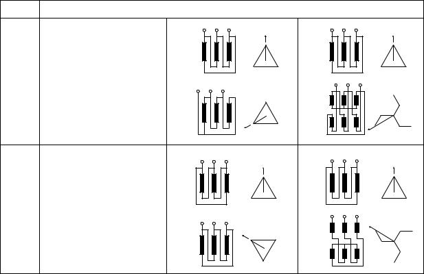
No.* |
Wire connection and phase sequence (Vector group symbols) |
|
|
Dd8 |
Dz8 |
8
Dd10 |
Dz10 |
10
*No. Phase shift number of hour;
The number represents the position of the hour hand of a clock as assuming the minute hand is at the position of zero minute. The voltage vector of lower winding is compared to the hour hand, and the voltage vector of higher winding is compared to the minute hand.
5.Measurement of Winding Resistance (for oil-immersed and dry type)
(1)Oil-immersed type
Winding resistance of transformers shall be measuredfor each tap by using direct current. The difference between the measured value and the manufacturers’ standards shall be less than 2%.
As the measured value will change according to the temperature, it shall be modified as below.
235 * +75 R75=Rt× 235 * +t
R75 : winding resistance at 75 oC Rt : winding resistance at t oC
t : temperature when measurement was carried out
* = 235 for copper or 225 for aluminum.
The measurement shall be carried outas promptly as possible to avoid rise in temperature of windings.
(2)Dry type
Winding resistance of transformers shall be measuredfor each tap by using direct current. The difference between the measured valueand the manufacturers’ standards shall withinbe manufacturers’ criteria.
20
Cold-winding resistance measurements are normally converted to a standard reference temperature equal to rated average winding temperature rise plus 20 °C. In addition, it may be necessary to convert the resistance measurements to the temperature at which the impedanceloss measurements were made. The conversions are accomplished by the following formula.
Rs = Rm {(Ts + Tk) / (Tm + Tk)} where
Rs is resistance at desired temperature Ts Rm is measured resistance
Ts is desired reference temperature
Tk is 234.5 °C for copper and 225 °C for aluminum
Tm is the temperature at which resistance was measured NOTE:
The value of Tk is 225 °C for pure Electrical Conductor Grade (EC) aluminum. Tk may be as high as 240 °C for alloyed aluminum.
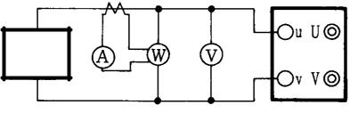
6. Measurement of No-load current and loss (for oil-immersed and dry type)
No-load current and loss shall be measured to confirm that there is no difference between measured value and the manufacturers’ standards.
The measurement shall be carried out on one winding with no wire connection by applying the rated voltage with the rated frequency to another winding.
If the implementation of the test by applying rated voltage is difficult, it is possible to apply lower voltage to check the balance of no-load current and loss between three phases.
If it is necessary, this test shall be implemented in consultation with manufacturer.
Transformer
Power supply
Figure 27 Testing circuit
7.Insulation Oil Test (for oil-immersed type)
(1)Test of new oil received from supplier
When insulation oil is received from supplier, the performance of oil shall be checked that it meets the standards shown in Table 27-7.
21
Table 27-7 Quality standards of new oil received from supplier
No. |
Items |
Standards |
|
|
|
|
|
|
Breakdown voltage (kV/2.5mm) |
|
|
1 |
Not less than: |
|
|
- Before filtering |
30 |
||
|
|||
|
- After filtering |
70 |
|
|
|
|
|
|
Dielectric loss angle (%) |
|
|
2 |
Not more than |
|
|
- at 25oC |
0.05 |
||
|
|||
|
- at 90oC |
0.50 |
|
3 |
Acidity (mgKOH/1g oil) |
|
|
Not more than |
0.02 |
||
|
|||
|
|
|
|
|
Water content (volume ppm) |
|
|
4 |
Not more than |
|
|
- In tank |
30 |
||
|
|||
|
- In drum |
40 |
|
|
|
|
|
|
Stability oxygenation resistance |
|
|
|
+ Method A: |
|
|
|
- Residue volume (%) Not more than |
0.01 |
|
5 |
- Acidity after oxygenation (mg KOH /1g of oil ) Not |
0.10 |
|
|
more than |
|
|
|
+ Method B: |
|
|
|
Time (minute) Not less than |
195 |
|
|
|
|
|
|
Dynamic viscosity (m2/s) |
|
|
6 |
Not more than |
|
|
- at 40oC |
12.0 |
||
|
|||
|
- at 50oC |
9.0 |
|
|
Density |
|
|
7 |
Not more than |
|
|
- at 15oC |
0.91 |
||
|
|||
|
- at 20oC |
0.90 |
|
8 |
Color-ASTM Scale |
0.5 |
|
Not more than |
|
||
|
|
||
|
|
|
|
|
Flash temperature (oC ) |
|
|
9 |
Not more than |
|
|
- Closed |
135 |
||
|
|||
|
- Open |
145 |
|
|
|
|
|
10 |
Sulfur corrosion |
Not |
|
|
|
|
|
11 |
Content of PCB(1) (ppm) |
5 |
|
12(*) |
Content of 2-furfural (ppm) |
|
|
Not more than |
0.1 |
||
|
|||
|
|
|
22
No. |
Items |
Standards |
|
|
|
|
|
13(*) |
Surface tension at 25oC (mN/m) |
|
|
Not less than |
40 |
||
|
|||
|
|
|
|
|
Content of anti-oxygenation (2) (%) |
|
|
14(*) |
- Not less than |
0.2 |
|
|
- Not more than |
0.4 |
|
|
|
|
Note:
(1)The limits of initial content of PCB in insulation oil in accordance with the law for environmental protection at the time of application.
(2)The standards are not mandatory for transformers sealed or protected by a plastic film.
(*)The test is not mandatory.
(2)Test of oil before installation
1)For acceptance test of new transformer, insulation oil shall be checkedthat it meets the standards shown in Table 27-8 before filling.
2)For transformers with voltage 110kV or more, insulation oil shall be filled after checking
that the sample oil |
immersed in the transformer meets the following criteria; |
Breakdown voltage is not |
less than 50kV(for 110-500 kV transformer), and water content |
is not more than 25ppm (for 100-220kV transformer), 20ppm (for 500kV transformer).
3)For transformers with voltage 110kV or more, insulation oil shall be checked that it meets the standards shown in Table 27-8 before filling in transformer.
4)When insulation oil is filled in transformer and transported to the installation location, the
insulation oil shall be checked |
that it meets the standards shown in item1,2 and 4 of |
||
Table 27-8 if the |
last oil |
test is |
more than 3 months ago. For transformer protected by a |
plastic film with |
voltage |
110kV |
or more, insulation oil shall be checked that it meets the |
standards shown in item 7 of Table 27-8.
(3)Test of oil for transformers in preservation process
1)For transformers in preservation process (standby state or storage).
2) |
For transformers with voltage 35 kV or lessshall be checked item 1 in Table 27-8 at least |
|
once a year. |
3) |
For transformers with voltage 110kV or moreshall be checked item 1-4 in Table 27-8 at |
|
least 3 months. |
(4) Test of new oil in new transformers before energizing
New oil in newtransformers before energizing shall be checked that it meets the standards of the standards shown in Table 27-8
23
Table 27-8 Insulation oil quality standards during installation and before energizing
|
|
|
|
|
|
|
Nominal Voltage (kV) |
|
||||
No. |
|
|
|
Items |
≤15 |
|
15-35 |
110 |
220 |
500 |
||
|
|
|
|
|
|
|||||||
|
|
|
|
|
|
|
|
|
||||
1 |
Breakdown voltage (kV/2.5mm) |
30 |
|
35 |
60 |
60 |
70 |
|||||
Not less than |
|
|||||||||||
|
|
|
|
|
|
|
|
|||||
2 |
Dielectric loss angle at 90oC (%) |
- |
|
- |
1.5 |
1.0 |
1.0 |
|||||
Not more than |
|
|||||||||||
|
|
|
|
|
|
|
|
|||||
3 |
Acidity (mgKOH/1g oil) |
0.02 |
|
0.02 |
0.02 |
0.02 |
0.02 |
|||||
Not more than |
|
|||||||||||
|
|
|
|
|
|
|
|
|||||
4 |
Water content (volume ppm) |
- |
|
- |
20(1) |
10 |
10 |
|||||
Not more than |
|
10 |
(2) |
|||||||||
|
|
|
|
|
|
|
||||||
5 |
Color - ASTM Scale |
1.0 |
|
1.0 |
1.0 |
1.0 |
0.5 |
|||||
|
|
|
|
|
|
|
||||||
Not more than |
Transparent, bright, no water and impurities |
|||||||||||
|
||||||||||||
|
|
|
|
|
|
|
|
|
||||
6 |
Content of impurities(3) |
|
|
No |
|
|
-/15/12 |
-/13/10 |
||||
ISO 4406-1991 |
(Visual observation) |
|
||||||||||
|
|
|
|
|||||||||
7 |
Total dissolved gas(3) (volume %) |
- |
|
- |
1 |
1 |
0.5 |
|||||
Not more than |
|
|||||||||||
|
|
|
|
|
|
|
|
|||||
8(*) |
Content of 2-furfural (ppm) |
|
- |
|
|
0.1 |
|
|||||
Not more than |
|
|
|
|
||||||||
|
|
|
|
|
|
|
|
|||||
9(*) |
Surface tension at 25 oC (mN/m) |
35 |
|
35 |
35 |
38 |
38 |
|||||
Not less than |
|
|||||||||||
|
|
|
|
|
|
|
|
|||||
|
Antioxidant stability |
|
|
|
|
|
|
|
||||
|
+ Method A: |
|
|
|
|
|
0.01 |
|
||||
|
- Sludge volume (%) Not higher than |
|
|
|
|
|
|
|||||
10 |
- Acidity after oxidation (mgKOH/g) |
|
- |
|
|
0.10 |
|
|||||
|
Not higher than |
|
|
|
|
|
|
|
||||
|
+ Method B: |
|
|
|
|
|
195 |
|
||||
|
- Time (minute) Not less than |
|
|
|
|
|
|
|||||
|
|
|
|
|
|
|
|
|
||||
|
Dynamic viscosity (m2/s) |
|
|
|
|
|
|
|
||||
11 |
Not more than |
|
|
|
|
|
|
|
||||
- at 40 |
o |
C |
|
|
|
12 |
|
|
||||
|
|
|
|
|
|
|
|
|||||
|
- at 50 oC |
|
|
|
9 |
|
|
|||||
|
Density (g/cm3) |
|
|
|
|
|
|
|
||||
12 |
Not more than |
|
|
|
|
|
|
|
||||
- at 15 |
o |
C |
|
|
|
0.91 |
|
|
||||
|
|
|
|
|
|
|
||||||
|
- at 20oC |
|
|
|
0.90 |
|
|
|||||
|
Flash temperature (oC ) |
|
|
|
|
|
|
|
||||
13 |
Not more than |
|
|
|
|
|
|
|
||||
- Closed |
|
|
|
135 |
|
|
||||||
|
|
|
|
|
|
|||||||
|
- Open |
|
|
|
|
|
145 |
|
|
|||
14 |
Sulfur corrosion |
|
|
|
No |
|
|
|||||
15 |
Content of PCB (ppm) (4) |
|
|
|
5 |
|
|
|||||
Note:
The sign "-" in the table is not specified.
(1)For 110 kV transformer which is not protected by a plastic film.
(2)For 110 kV transformer which is protected by a plastic film.
24
(3)For 110 kV transformer which is protected by a plastic film.
(4)The limits of initial content of PCB in insulation oil in accordance with the law for environmental protection at the time of application.
(*)Test is not mandatory.
8.On-Line Tap Changer Inspection (for oil-immersed and dry type)
(1)Switching operation test
It shall be checked that On-Line Tap Changer (OLTC) can be switched both manually and by electric drive without any abnormality.
1)Operation test
Switching operation for eachtap shall be checked without voltage applicationIt. shall be checked that there is no change on OLTC both before and after operation. The time for tap change shall be measured to confirm that the measured value iswithin the manufacturers’ standards. It shall be checked that there is no abnormality on tap number indication.
2)Alarm test
Activation of tap-jam alarm shall be checked by turning off OLTC, while OLTC is operated.
(2)Measurement of current of electric motors
Current of electric motors shall be measured to confirm that OLTC switches smoothly without any abnormality on electric drive mechanism. The current shall be within the manufacturers’ standards.
(3)Oil test in OLTC
For transformers with OLTC compartment, insulation oil used in OLTC shall be checked that it
|
meets the standards |
in manufacturer's instructions |
as required for insulation oil of the |
||||||||
|
transformer. If |
there |
are nomanufacturer's instructions, the quality |
of oil shall |
meetthe |
||||||
|
standards shown in Table 27-9. |
|
|
|
|
|
|
|
|||
|
|
Table 27-9 Quality standards of oil in OLTC compartment before energizing |
|
||||||||
|
|
|
|
|
|
|
|
|
|
|
|
|
|
|
|
|
|
|
Limit values |
|
|||
|
|
|
|
|
|
|
|
|
|
||
No. |
|
|
Items |
For OLTC |
|
For OLTC connected the |
|||||
|
|
connected to |
|
beginning or middle of the coil |
|||||||
|
|
|
|
|
|
||||||
|
|
|
|
|
the neutral |
|
Nominal voltage (kV) |
|
|||
|
|
|
|
|
point |
|
≤ 35 |
|
110-220 |
|
500 |
1 |
|
Breakdown voltage (kV/2.5mm) |
40 |
|
35 |
|
50 |
|
60 |
||
|
Not less than |
|
|
|
|
|
|||||
|
|
|
|
|
|
|
|
|
|
|
|
2 |
|
Water content (volume ppm) |
30 |
|
- |
|
25 |
|
20 |
||
|
Not more than |
|
|
|
|
||||||
|
|
|
|
|
|
|
|
|
|
||
9. Bushing CT Inspection (for oil-immersed and dry type) |
|
|
|
|
|
|
|||||
It shall be carried out according to the inspection items specified separately in Article 29. |
|
||||||||||
25
10.Cooling System and auxiliary system Inspection (for oil-immersed and dry type)
(1)Cooling system
Cooling systems of transformer shall be inspected to confirm that pumps and fans operate without any abnormality. Phase rotations shall be checkedif it meetsthe manufacturers’ specifications. Current of the cooling systems shall be measured if it meets the manufacturers’ specifications.
(2)Auxiliary system
-The operation of hot line oil filter shall be checked that there is no abnormality.
-It shall be checked that alarms are activated appropriately by operating mechanical relays such as sudden oil pressure relay and hydraulic relay artificially.
-It shall be checked that the indication of thermometer is within the manufacturers’ standards.
11.Withstand Voltage Test (for oil-immersed and dry type)
Withstand voltage test shall be carried out after installation on site if it is necessary.
The methods of withstand voltage test are as follows:
(1)Test method of IEC or Vietnamese standard (regulated for equipment individually)
(2)Test method of Japanese standard (regulated for all equipment comprehensively)
The test shall becarried out according to test method of IEC etc.preferentially, and be carried out according to test method ofJapanese standard alternatively if it is difficult to apply the former method. If it is uncertain about test method, test shall be carried out in consultation with manufacturer.
(1)Test method of Vietnamese standard (regulated in Vietnamese standard “QUY TRÌNH THÍ NGHIỆM MÁY BIẾN ÁP LỰC PHẦN I: MÁY BIẾN ÁP”)
Withstand voltage test should be carried out to check the ability for temporary overvoltage of windings, cores and other insulated parts of transformers.
The test voltage is specified inTable 27-8 and 27-9, Column 3. The duration of withstand voltage test is 1 minute. The detailed test program shall be referred to Vietnamese standard “QUY TRÌNH THÍ NGHIỆM MÁY BIẾN ÁP LỰC PHẦN I: MÁY BIẾN ÁP”.
For transformers which have already been in service and have been refurbished or serviced, withstand voltage tests shall be repeated at test levels of 80% of the original value (Table 2710 and 27-11, column 3).
26
Table 27-10 Withstand voltage for transformer windings Um ≤ 170kV
Maximum voltage on |
Withstand basic impulse |
Short-duration power frequency withstand |
|||||||||||||
equipment Um |
lightening (BIL) |
|
voltage* |
||||||||||||
(kV rms) |
(kV peak) |
|
(kV rms) |
||||||||||||
|
|
|
|
40 |
|
|
|
|
|
|
|
||||
7.2 |
|
|
|
|
|
|
|
|
|
|
|
|
|
|
20 |
|
|
|
|
60 |
|
|
|
|
|
|
|||||
|
|
|
|
|
|
|
|
|
|
|
|||||
12 |
|
|
|
|
|
|
|
|
|
|
28 |
||||
|
|
|
|
|
|
|
|
|
|
|
|||||
17.5 |
|
|
75 |
|
|
|
|
|
|
|
|||||
|
|
|
|
|
|
|
|
|
38 |
||||||
|
|
|
|
|
|
|
|
|
|
|
|||||
24 |
|
|
|
95 |
|
|
|
|
|
|
|
||||
|
|
|
|
|
|
|
|
|
|
50 |
|||||
|
|
|
|
125 |
|
|
|||||||||
|
|
|
|
|
|
|
|
|
|
|
|||||
36 |
|
|
|
145 |
|
|
|
|
|
|
70 |
||||
|
|
|
|
|
|
|
|
|
|
|
|
|
|
|
|
|
|
|
|
170 |
|
|
|
|
|
|
|||||
|
|
|
|
|
|
|
|
|
|
|
|||||
52 |
|
|
|
|
|
|
|
250 |
|
|
|
95 |
|||
|
|
|
|
|
|
|
|
|
|
||||||
60 |
|
|
|
|
280 |
|
|
|
115 |
||||||
|
|
|
|
|
|
||||||||||
72.5 |
|
|
|
|
325 |
|
|
|
140 |
||||||
|
|
|
|
|
|
|
|||||||||
100 |
|
|
|
|
380 |
|
|
|
150 |
||||||
|
|
|
|
|
|
|
|||||||||
123 |
|
|
|
|
450 |
|
|
|
|
185 |
|||||
|
|
|
|
|
|
|
|
||||||||
145 |
|
|
|
550 |
|
|
|
|
230 |
||||||
|
|
|
|
|
|
|
|||||||||
170 |
|
|
|
650 |
|
|
|
275 |
|||||||
|
|
|
|
|
|
||||||||||
|
|
|
|
750 |
|
|
|
325 |
|||||||
|
|
|
|
|
|
|
|||||||||
*Note : for transformers which have already been in service and have been refurbished or serviced, test voltage is 80% of column 3.
27
Table 27-11 Withstand voltage for transformer windings Um > 170kV
Maximum voltage on |
Withstand basic impulse |
Short-duration power frequency withstand |
equipment Um |
lightening (BIL) |
voltage * |
(kV rms) |
(kV peak) |
(kV rms) |
|
650 |
325 |
245 |
|
|
750 |
|
|
|
|
|
|
|
360 |
245 |
850 |
|
|
|
|
|
|
395 |
245 |
950 |
|
|
|
|
245 |
1050 |
460 |
|
|
|
550 |
1175 |
510 |
|
|
|
550 |
1300 |
|
|
570 |
|
|
|
|
550 |
1425 |
|
|
630 |
|
|
|
|
550 |
1550 |
|
|
680 |
|
|
1675 |
|
|
|
550 710
710
1800
*Note : for transformers which have already been in service and have been refurbished or serviced, test voltage is 80% of column 3.
(2) (Reference) Test method of Japanese standard
The test voltage is shown in Table 27-12 and applying time is for 10 minutes.
28

Table 27-12 Test voltage for withstand voltage test
Nominal |
Highest |
Test |
|
|
Voltage |
voltage for |
|
|
|
of system |
equipment |
voltage |
Derivation |
Neutral grounding system |
(Un) |
(Um) |
[kV] |
|
|
[kV] |
[kV] |
|
|
|
6 |
7.2 |
10.8 |
1.5 times of Um |
All type |
10 |
12 |
15.0 |
1.25 times of Um |
All type |
15 |
17.5 |
21.9 |
1.25 times of Um |
All type |
22 |
24 |
30.0 |
1.25 times of Um |
All type |
35 |
38.5 |
48.1 |
1.25 times of Um |
All type |
|
|
135.3 |
1.1 times of Um |
Resistance grounded system |
|
|
|
|
Solidly grounded system(The |
|
|
88.6 |
0.72 times of Um |
following cases are |
|
|
excluded.apply to switching |
||
|
|
|
|
|
110 |
123 |
|
|
station, etc.) |
|
|
Solidly grounded system(apply |
||
|
|
|
|
|
|
|
|
|
to a power station, substation, |
|
|
78.7 |
0.64 times of Um |
and the like to which the |
|
|
|
|
neutral line is solidly |
|
|
|
|
grounded.) |
|
|
|
|
Solidly grounded system(The |
|
|
176.4 |
0.72 times of Um |
following cases are |
|
|
excluded.apply to switching |
||
|
|
|
|
|
|
245 |
|
|
station, etc.) |
220 |
|
|
Solidly grounded system(apply |
|
|
|
|
|
to a power station, substation, |
|
|
156.8 |
0.64 times of Um |
and the like to which the |
|
|
|
|
neutral line is solidly |
|
|
|
|
grounded.) |
|
|
|
|
Solidly grounded system(The |
|
|
396.0 |
0.72 times of Um |
following cases are |
|
|
excluded.apply to switching |
||
|
|
|
|
|
|
550 |
|
|
station, etc.) |
500 |
|
|
Solidly grounded system(apply |
|
|
|
|
|
to a power station, substation, |
|
|
352.0 |
0.64 times of Um |
and the like to which the |
|
|
|
|
neutral line is solidly |
|
|
|
|
grounded.) |
Test voltage of withstand voltage test is defined as the highest voltage multiplied by a margin.
At lower voltage levels, the margin is set to 1.5 since surge voltage etc. affect considerably.However, as the voltage level becomes higher, the effect becomes less, the margin is set to smaller value.
At solidly grounded neutral system, smaller test voltage can be used since voltage rise of thesound phases at the time of single line-to-ground fault is smaller than that of ungrounded neutral system and resistance neutral system.
29

Article 28. The inspection item for Potential Transformers (PT)
1. Visual Inspection
It shall be checked whether the PT has abnormalities such as oil leakage, crack, breakage, damage, looseness at screwed parts, etc. or not.
2.Measurement of Insulation Performances
(1)Insulation resistance for windings
Insulation resistance between a winding and the ground, and between windings shall be measured by a 2,500V megger. Standards of the insulation resistance by types are in Table 28-1.
1) Winding type
Table 28-1 Standards of Insulation resistance for winding type PT (MΩ)
Oil temperature
Nominal |
20°C |
30°C |
40°C |
50°C |
60°C |
|
|
|
|
|
|
Voltage (kV) |
|
|
|
|
|
110 and over |
1,200 |
600 |
300 |
150 |
75 |
22 - 35 |
1,000 |
500 |
250 |
125 |
65 |
10 - 15 |
800 |
400 |
200 |
100 |
50 |
Lower than 10 |
400 |
200 |
100 |
50 |
25 |
2)Condenser-type and dry mold-type
Insulation resistance of primary windings shall be 100 MΩ and more.
3)SF6 gas insulation-type
Insulation resistance of primary windings shall be more than manufacturers’ standards.
(2)Insulation resistance for control circuits
Insulation resistance between control circuits and the ground shall be measured by a 500V or 1,000V megger to confirm that it is more than 2 MΩ.
(3)Measurement of dielectric loss
The dielectric loss angle (tanδ) and capacitance for coupling condenser of bushing |
shall be |
measured to confirm that themeasured value is within the manufacturers’ standards. |
This |
measurement is relevant to CVT of voltage 110 kV and over. |
|
3. Measurement of Transformation Ratio
Transformation ratio shall be measured for eachsecondary output of PT. The measurement shall be performed with the PT being connected to control boards. With the primary circuit of PT being energized, the voltage of secondary circuit shall be measured at the test terminal on control board in order to confirm comprehensively that the transformation ratio and the wire connection are adequate.
The measured value shall be checked if it meets the criteria as below in accordance with the accuracy classes of PT.
30
Table 28-2 Limits of voltage error and phase displacement for measuring PT
|
|
(IEC60044-2) |
|
Accuracy |
Voltage (ratio) error % |
Phase displacement |
|
class |
(Minutes) |
||
|
|||
0.1 |
From -0.1 to +0.1 |
From -5 to +5 |
|
|
|
|
|
0.2 |
From -0.2 to +0.2 |
From -10 to +10 |
|
|
|
|
|
0.5 |
From -0.5 to +0.5 |
From -20 to +20 |
|
|
|
|
|
1.0 |
From -1.0 to +1.0 |
From -40 to +40 |
|
|
|
|
|
3.0 |
From -3.0 to +3.0 |
Not specified |
|
|
|
|
Table 28-3 Limits of voltage error and phase displacement for protective PT
|
|
(IEC60044-2) |
|
Accuracy |
Voltage (ratio) error % |
Phase displacement |
|
class |
(Minutes) |
||
|
|||
3P |
From -3.0 to +3.0 |
From -120 to +120 |
|
|
|
|
|
6P |
From -6.0 to +6.0 |
From -240 to +240 |
|
|
|
|
4. Polarity Test
Polarity of PT shall be checked. The primary circuit of PT shall be connected to a tester,andthe polarity of the secondary circuit shall be checked if it meets the manufacturers’ specifications.
5. Measurement of Winding Resistance
It shall be carried out according to the inspection items specified separately in Article 27.
6. Measurement of No-load current and loss
It shall be carried out according to the inspection items specified separately in Article 27.
7. Insulation oil test before energizing
New insulation oil for sealed or open typeshall be checked that it meets the standards shown in Table 28-4 before filling.
31
Table 28-4 Quality standards of new insulation oil for PT before energizing
No. |
Items |
|
Nominal Voltage (kV) |
|
|||
≤15 |
22, 35 |
110 |
220 |
500 |
|||
|
|
||||||
|
|
|
|
|
|
|
|
1 |
Breakdown voltage (kV/2.5mm) |
30 |
35 |
60 |
60 |
70 |
|
Not less than |
|||||||
|
|
|
|
|
|
||
2 |
Dielectric loss angle at 90oC (%) |
- |
- |
1.5 |
1.0 |
1.0 |
|
Not more than |
|||||||
|
|
|
|
|
|
||
3 |
Acidity (mgKOH/1g oil) |
0.02 |
0.02 |
0.02 |
0.02 |
0.02 |
|
Not more than |
|||||||
|
|
|
|
|
|
||
4 |
Color - ASTM Scale |
1.0 |
1.0 |
1.0 |
1.0 |
0.5 |
|
Not more than |
Transparent, bright, no water and impurities |
||||||
|
|||||||
|
|
|
|
|
|
|
|
5 |
Water content (volume ppm) |
- |
- |
10 |
10 |
10 |
|
Not more than |
|||||||
|
|
|
|
|
|
||
6 |
Total dissolved gas (volume %) |
- |
- |
|
1 |
|
|
Not more than |
|
|
|||||
|
|
|
|
|
|
||
Note: |
|
|
|
|
|
|
|
-Item 5 and 6 are mandatory for measuring transformers with voltage 110 kV or more.
-The sign "-" in the table is not specified.
8. Withstand Voltage Test
Withstand voltage test shall be carried out after installation on site if it is necessary. The methods of withstand voltage test are as follows:
(1)Test method of IEC or Vietnamese standard (regulated for equipment individually)
(2)Test method of Japanese standard (regulated for all equipment comprehensively)
The test shall becarried out according to test method of IEC etc.preferentially, and be carried out according to test method ofJapanese standard alternatively if it is difficult to apply the former method. If it is uncertain about test method, test shall be carried out in consultation with manufacturer.
(1)Test method of IEC (power frequency test for instrument transformer regulated in IEC60044-2)
1)The test voltage is specified in Table 28-5, Column 4. The duration of withstand voltage test is 1 minute.
The detailed test program shall be decided between manufacturer and user.
32

Table 28-5 On site test voltages
Nominal voltage |
Highest voltage |
Rated lightning |
On-site short- |
Rated short- |
|
of system |
for equipment |
impulse |
duration power- |
duration power- |
|
|
|
withstand |
frequency |
frequency |
|
Un |
Ur |
voltage (BIL) |
withstand |
withstand |
|
kV (peak) |
voltage |
voltage |
|||
kV (r.m.s.) |
kV (r.m.s.) |
||||
|
Uds |
Ud |
|||
|
|
|
|||
|
|
|
kV (r.m.s.) |
kV (r.m.s.) |
|
[1] |
[2] |
[3] |
[4] |
[5] |
|
|
|
|
|
|
|
6 |
7.2 |
40 |
16 |
20 |
|
60 |
|||||
|
|
|
|
||
|
|
60 |
|
|
|
10 |
12 |
75 |
22.4 |
28 |
|
|
|
95 |
|
|
|
15 |
17.5 |
75 |
30.4 |
38 |
|
95 |
|||||
|
|
|
|
||
|
|
|
|
|
|
|
|
95 |
|
|
|
22 |
24 |
125 |
40 |
50 |
|
|
|
145 |
|
|
|
|
|
|
|
|
|
|
|
155 |
|
|
|
35 |
38.5 |
180 |
60 |
75 |
|
|
195 |
|
|
||
|
|
|
|
||
|
|
|
|
|
|
|
40.5 |
190 |
64 |
80 |
|
|
|
|
|
|
|
110 |
123 |
450 |
148 |
185 |
|
550 |
184 |
230 |
|||
|
|
||||
|
|
|
|
|
|
|
|
850 |
288 |
360 |
|
220 |
245 |
950 |
316 |
395 |
|
|
|
1050 |
368 |
460 |
|
|
|
|
|
|
|
|
|
1175 |
408 |
510 |
|
500 |
550 |
1300 |
456 |
570 |
|
1425 |
488 |
610 |
|||
|
|
||||
|
|
1550 |
544 |
680 |
|
|
|
|
|
|
Note :
- The on-site test voltages have been calculated as follows: Uds (on-site test value) = Ud × 0.8 (column [4])
- The above test voltage is applied for only uniformly insulated high-voltage windings. - Frequency is from 45 to 65Hz
2)For the earthed PT, the test shall excite the secondary winding. The test voltage and duration of the test are as follows.
-Test Voltage = 1.3 * 110V/
 3 (Frequency is from 45 to 65Hz)
-Duration: 5 minutes
33
(2)(Reference) Test method of Japanese standard The details are specified in item 11 of article27.
Article 29. The inspection item for Current Transformers (CT)
1. Visual Inspection
It shall be checked whether the CT has abnormalities such as oil leakage, crack, breakage, damage, looseness at screwed parts, etc. or not.
2.Measurement of Insulation Performance
(1)Insulation resistance of primary windings
Insulation resistance between a winding and the ground, and |
between windings shall be |
|||||||
measured by a 2,500V megger. Standards of the insulation resistance by types are in Table 29-1. |
||||||||
1) Porcelain-type |
|
|
|
|
|
|
|
|
Table 29-1 Standards of insulation resistance for porcelain type CT |
||||||||
|
|
|
|
|
|
|
(MΩ) |
|
Oil |
|
|
|
|
|
|
|
|
temperature |
|
20°C |
30°C |
40°C |
50°C |
|
60°C |
|
Nominal |
|
|
|
|||||
|
|
|
|
|
|
|
|
|
Voltage (kV) |
|
|
|
|
|
|
|
|
110 and over |
|
1,200 |
600 |
300 |
150 |
|
75 |
|
22 - 35 |
|
1,000 |
500 |
250 |
125 |
|
65 |
|
10 - 15 |
|
800 |
400 |
200 |
100 |
|
50 |
|
Lower than 10 |
|
400 |
200 |
100 |
50 |
|
25 |
|
2)Bushing -type
Not necessary to measure insulation resistance of windings.
(2)Insulation resistance of secondary circuits and control circuits
Insulation resistance of secondary circuits and control circuits shall be measured by a 500Vor 1,000V megger to confirm that they are more than 2 MΩ.
(3)Measurement of dielectric loss
Only oiled CT (with oil paper insulation) is relevant. The dielectric loss angle (tanδ) should be measured for the CT of nominal Voltage 110 kV or over. The measured valuetanof δ at temperature +20 oC should not exceed the values stipulated separately in Table 29-2.
Table 29-2 Standards of tan δ for CT
Test Object |
Dielectric loss value tanδ% at nominal voltage (kV) |
|||
35 |
110 |
220-500 |
||
|
||||
Oiled CT |
2.5 |
2 |
1.5 |
|
(with oil paper insulation) |
||||
|
|
|
||
34
3. Measurement of Winding Resistance
It shall be carried out according to the inspection items specified separately in Article 27.
4. Measurement of Transformation Ratio
Transformation ratio shall be measured for eachoutput of CT. The measurement shall be performed with the CT being connected to control boards. With the primary circuit of CT being applied test current, the current on control board shall be measured in order to comprehensively confirm that the transformation ratio and the wire connection are adequate.
The measured value shall be checked if it meets the criteria asbelow in accordance with the accuracy classes of CT.
Table 29-3 Limits of current error and phase displacement for measuring CT
(Classes from 0.1 to 1.0) (IEC60044-1)
|
Percentage current (ratio) error at |
Phase displacement at percentage of |
||||||||
|
percentage of rated current shown |
|||||||||
|
rated current shown below (Minutes) |
|||||||||
Accuracy |
|
|
below |
|
||||||
|
|
|
|
(From -* to +*) |
|
|||||
|
(From -* to +*) |
|
|
|
||||||
class |
|
|
|
|
|
|
||||
|
Primary current% |
|
|
Primary current% |
|
|||||
|
|
|
|
|
||||||
|
5 |
20 |
|
100 |
|
120 |
5 |
20 |
100 |
120 |
0.1 |
0.4 |
0.2 |
|
0.1 |
|
0.1 |
15 |
8 |
5 |
5 |
0.2 |
0.75 |
0.35 |
|
0.2 |
|
0.2 |
30 |
15 |
10 |
10 |
0.5 |
1.5 |
0.75 |
|
0.5 |
|
0.5 |
90 |
45 |
30 |
30 |
1.0 |
3.0 |
1.5 |
|
1.0 |
|
1.0 |
180 |
90 |
60 |
60 |
* Range of standards
Ex.) The range of standard for a CT of accuracy class 0.1 applying 5% of primary current is from- 0.4% to +0.4%.
Table 29-4 Limits of current error and phase displacement for measuring CT for special application
(IEC60044-1)
|
Percentage current(ratio) error at |
Phase displacement at percentage of |
|||||||||
|
percentage of rated current shown |
||||||||||
|
rated current shown below (Minutes) |
||||||||||
Accuracy |
|
|
below |
|
|
||||||
|
|
|
|
|
|
(From -* to +*) |
|
||||
|
(From -* to +*) |
|
|
|
|
||||||
class |
|
|
|
|
|
|
|
|
|||
|
Primary current% |
|
|
Primary current% |
|
||||||
|
|
|
|
|
|||||||
|
1 |
5 |
20 |
100 |
120 |
1 |
5 |
|
20 |
100 |
120 |
0.2S |
0.75 |
0.35 |
0.2 |
0.2 |
0.2 |
30 |
15 |
|
10 |
10 |
10 |
0.5S |
1.5 |
0.75 |
0.5 |
0.5 |
0.5 |
90 |
45 |
|
30 |
30 |
30 |
35
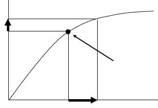
Table 29-5 Limits of error for protective CT
|
|
|
(IEC60044-1) |
|
Accuracy |
Current error at rated |
Phase displacement at |
Composite error at rated |
|
rated primary current |
accuracy limit primary |
|||
class |
primary current % |
|||
(Minutes) |
current % |
|||
|
|
|||
5P |
From -1 to +1 |
From -60 to +60 |
5 |
|
10P |
From -3 to +3 |
- |
10 |
|
“P”indicates protection. |
|
|
||
|
Table 29-6 imits of error for PR protective CT |
|||
|
|
|
(IEC60044-1) |
|
Accuracy |
Current error at rated |
Phase displacement at |
Composite error at rated |
|
rated primary current |
accuracy limit primary |
|||
class |
primary current % |
|||
Minutes |
current % |
|||
|
|
|||
5PR |
From -1 to +1 |
From -60 to +60 |
5 |
|
10PR |
From -3 to +3 |
- |
10 |
|
"PR" indicates protection low remanence.
5. Polarity Test
Polarity of CT shall be checked. The primary circuit of CT shall be connected to a tester,and the polarity of the secondary circuit shall be checked if it meets the manufacturers’ specifications.
6. Measurement of Excitation Characteristics
Excitation Characteristics shall be measured to check the change of the characteristics caused by any core movement or gap. Only those CT that have split-type cores are relevant.
The measurement result shall be compared with factory inspection records to confirm that there is no difference.
The saturation point* (knee point) shall be checked in measurementI. case of measurement, the voltage applying to secondary circuit shall be with the rated frequency, and the other terminals shall be opened.
Excitation |
|
voltage |
Excitation curve |
10%up |
|
Saturation point (Knee point)
50%up |
Excitation |
|
current |
Figure 29 The image of Excitation Characteristics
36
*Saturation point
As it is shown in Figure 30, excitation current is proportionally risen with excitation voltage, but it is increased substantially at a certain point. The saturation point is the lowest point where the measuring current increases 50% as a result of increasing the applying voltage 10%.
7. Insulation oil test before energizing
The details are specified in item 7 of artilcle28.
8. Withstand Voltage Test
Withstand voltage test shall be carried out after installation on site if it is necessary.
The methods of withstand voltage test are as follows:
(1)Test method of IEC or Vietnamese standard (regulated for equipment individually)
(2)Test method of Japanese standard (regulated for all equipment comprehensively)
The test shall becarried out according to test method of IEC etc.preferentially, and be carried out according to test method ofJapanese standard alternatively if it is difficult to apply the former method. If it is uncertain about test method, test shall be carried out in consultation with manufacturer.
(1)Test method of IEC (power frequency test for current transformer regulated in IEC60044-1) The details are specified in item 8 of article28.
(2)(Reference) Test method of Japanese standard The details are specified in item 11 of article27.
Article 30. The inspection item for Gas Circuit Breaker (GCB)
1. Visual Inspection
It shall be checked whether GCB has abnormalities such as gas leakage, crack, breakage, damage, looseness at screwed parts, etc. or not.
Gas leakage test shall be carried out to confirm that the leakage is not detected by a gas leak detector. The criterion of gas leakage to the atmosphere is less than 1% per year.There are two test methods; they are accumulation method and trace method.The former is the standard method, the latter is used only for the part that the accumulation method can not be carried out easily.
(1)Accumulation method
Surround binding parts of a tankand whole circumferenceof gas fitting with polyethylene sheets, the accumulated leakage gas in the sheets shall be detected witha gas leak detector after the appropriate time elapsed.
(2)Trace method
The existence of gas leakage is checked by bringing a gas leak detector close to connection parts of a tank and gas piping directly.
37
Figure 30 Accumulation method
2.Measurement of Insulation Resistance
(1)Insulation resistance of main circuits
Insulation resistance shall be measured by a 2,500Vmegger in the following case. Standards of the insulation resistance are in Table 30-1.
-Between main circuits and the ground at the time of ON
-Between poles of main circuits at the time of OFF
(2)Insulation resistance of control circuits
Insulation resistance of control circuits(including motors for motor springoperation) shall be measured by a 500V or 1,000V megger. Standards of the insulation resistance are in Table 30-1.
Table 30-1 Standards of insulation resistance for GCB
Test object |
|
Nominal voltage (kV) |
Standards (MΩ) |
|
|
|
|
Main circuit |
|
110 and over |
1,000 and more |
|
35 and less |
500 and more |
|
|
|
||
|
Control circuit |
2 and more |
|
NOTE
-The equipment which has been charged once shall be discharged before measurement sufficiently.
-In case of measurement of one phase, other 2 phases shall be grounded.
-In case of measurement, stringings shall be disconnected from main circuits as far as possible. The surface of insulators shall be cleaned and dried sufficiently.
-Measured value shall be recorded after 1 minute of applying the test voltage, and temperature, weather, etc. shall be recorded.
3.Measurement of Contact Resistance for Direct Current
Contact resistance of primary circuits shall be measured and checkedif it meets the manufacturers’ standards.
Contact resistance can be calculated bydividing the measured voltage between terminals by applied current. Direct current more than 50A shall be applied for measurement.
38
4.Gas Density alarm or Gas Pressure alarm Test
(1)SF6 gas pressure that detectors are activated for alarm and lock of operation of GCB
It shall be checked that larm and lock of operation of GCB are activated bylowering the gas pressure by valve operation. SF6 gas pressure at which detectors are activatedfor alarm and lock of operation of GCB shall be checked that it meets manufacturers’ standards.
(2)SF6 gas pressure that alarm and lock of operation of GCB are reset
It shall be checked that alarm and lock of operation of GCB are reset by heightening gasthe pressure by valve operation. SF6 gas pressure at which alarm and lock of operation of GCB are reset shall be checked that it meets manufacturers’ standards.
Measured value shall be modified according to the difference between temperature when measurement was carried out and one in manufacturers’standards by using the formula as below.
P20=Pt × 273.15 +20 273.15 +t
P20 : gas pressure at 20 oC Pt : gas pressure at t oC
t : temperature when measurement was carried out
5.Opening and Closing Operations Test
(1)Manual opening and closing operations test
It shall be checked that there is no abnormality in GCB by openingndaclosing it 3 times by manual handle or press button in the field.
(2)Opening and closing operations test by remote control
It shall be checked that there is no abnormality in GCB by opening and closing it 3 times at the rated voltage (pressure) by remote control.
(3)Continuous opening and closing operations test
It shall be checked that there is no abnormality in GCB openingby and closing it 20 times continuously at the rated voltage (pressure).
(4)Trip free mechanism test
A GCB that has no trip-free mechanism is irrelevant. The test procedure is as below.
-It shall be confirmed that GCB is opened immediately and not closed again during closing operation if tripping command is inputted.
-After that, it shall be confirmed that GCB can be closed again if closing command is canceled once, then closing command is inputted again. (Anti-pomping test)
6.Measurement of Opening and Closing Characteristics
(1)Contact opening time and closing time
Contact opening time and closing time shall be measured and checkedif they are within the manufacturers’ standards.
(2)Minimum operational voltage (pressure)
In the state |
whic |
voltage |
is not applied to the primary |
circuit, either the voltage of |
electromagnetic |
coil |
or the |
pressure of compressed air(oil) shall |
be maintained athe rated |
39
value, and the minimum voltage or pressure shall be measured by changing the other parameter (pressure or voltage). At this time, the opening-and-closing speed characteristic of GCB does not meet the manufacturers’ specifications.
The value of minimum operating voltage (pressure) is shown in Table 30-2.
Table 30-2 Minimum operating voltage (pressure)
(IEC62271-100)
Items |
Standards |
|
|
|
|
Minimum closing voltage |
85% of the rated voltage |
|
Minimum opening voltage |
85% of the rated voltage if AC |
|
70% of the rated voltage if DC |
||
|
||
Minimum closing pressure |
85% of the rated pressure |
|
(For pneumatic or oil pressure drive) |
||
|
||
Minimum opening pressure |
85% of the rated pressure |
|
(For pneumatic or oil pressure drive) |
||
|
(3)Operating sequence
It shall be confirmed that the operating sequence of GCB meets the standards as below.
Table 30-3 Operating sequence for GCB
|
(IEC62271-100) |
Operating sequence |
Note |
|
|
O - 3min - CO - 3min - CO |
For CB not intended for rapid auto-reclosing |
|
|
O - 0.3s - CO - 3min* - CO |
For CB intended for rapid auto-reclosing |
|
|
CO - 15s - CO |
For CB not intended for rapid auto-reclosing |
|
|
* instead of 3min, other values 15s and 1min are also used for CB intended for rapid autoreclosing.
Orepresents an opening operation
CO represents a closing operation followed immediately (that is, without any intentional delay) by an opening operation
(4)Three phase imbalance
Three phase imbalance of opening and closing time shall be measured and checked if it meets the standards as below.
Table 30-4 Standards of three phase imbalance
|
(IEC62271-100) |
Operation |
Standards |
Open |
3.3ms and less |
Close |
5ms and less |
40
(Reference from IEC62271-100)
-If one pole consists of more than one interrupter unit connected inseries, the maximum difference between the instants of contactstouching within these series connected interrupter units shall not exceed a sixth of a cycle of rated frequency.
- Where closing resistorsare used, the maximum difference between the instants of contacts touching during closing in the individual closing resistors shall notexceed half a cycle of rated frequency.
-If on one pole more than oneindividual closing resistor is used, each assigned to one of the interrupter units which are connected in series, the maximumdifference between the instants of contacts touching within these series connected closing resistors shall not exceed a third of a cycle
of rated frequency.
-If one pole consists of more than one interrupter unit connected inseries, the maximum difference between the instants of contactseparation within these series connected interrupter units shall not exceed an eighth of a cycle of rated frequency.
7. Associated Tank Capacity
Only those GCB that have pneumatic or oil pressure drive are relevant. It shall be confirmed that GCB can be opened and closed consecutively (more than twice for those GCB that have duties to reclose) when the associated tank is not connected to driving sources (pressurized air or power source).
8.Interlocking System Test
(1)Locking by oil pressure drive
Only those GCB that have oil pressure drive are relevant. It shall be confirmed that GCB cannot be opened or closed when oil pressure is lower than the regulation level.
(2)Locking by pneumatic drive
Only those GCB that have pneumatic drive are relevant. It shall be confirmed that GCB cannot be opened or closed when air pressure is lower than the regulation level.
9.Operation Test of Safety Valve
Only those GCB that have pneumatic or oil pressure drive are relevant. It shall be confirmed the safety valve operates when the air or oil pressure rises to the tank maximum allowable pressure.
10. Bushing CT Inspection
It shall be carried out according to the inspection items specified separately in Article29if it is necessary.
11. Check of SF6 gas quality
The purity and water content in SF6 gas enclosed in equipment shall be checked as directed by manufacturer. Maximum allowable moisture to ensure no dew condensation is converted to dew point not more than -5°C. (Converted to rated pressure of equipment at 20 °C) (refer to IEC62271-1: 2011)
If there are no standards ofSF6 gas in manufacturer’s instructions, it shall meet the standards shown in table 30-5.
41
Table 30-5 Standards of SF6 gas quality before energizing
|
|
|
(GB / T 8905-1996) |
|
Items |
|
Standards |
|
|
|
|
|
Gas purity |
|
97 vol. %and more |
|
Equipment with current interruption |
150ppm or less |
|
Water content |
Equipment |
without |
500ppm or less |
|
interruption |
|
|
|
|
|
|
Note: Inspection of water content shall be carried out after 24 hours after filling gas.
12. Withstand Voltage Test
Withstand voltage test shall be carried out after installation on site if it is necessary.
The methods of withstand voltage test are as follows:
(1)Test method of IEC or Vietnamese standard (regulated for equipment individually)
(2)Test method of Japanese standard (regulated for all equipment comprehensively)
The test shall becarried out according to test method of IEC etcpreferentially,. and be carried out according to test method ofJapanese standard alternatively if it is difficult to apply the former method.If it is uncertain about test method, test shall be carried out in consultation with manufacturer.
(1)Test method of IEC (power frequency test for current transformer regulated in IEC60694)
The test voltage is specified in Table 30-6, Column 4. The duration of withstand voltage test is 1 minute.
The detailed test program shall be decided between manufacturer and user.
42

Table 30-6 On site test voltages
Nominal voltage |
Highest voltage |
Rated lightning |
On-site short- |
Rated short- |
|
duration power- |
duration power- |
||||
of system |
for equipment |
impulse |
frequency |
frequency |
|
Un |
Ur |
withstand |
withstand |
withstand |
|
voltage (BIL) |
voltage |
voltage |
|||
kV (r.m.s.) |
kV (r.m.s.) |
kV (peak) |
Uds |
Ud |
|
|
|
|
kV (r.m.s.) |
kV (r.m.s.) |
|
[1] |
[2] |
[3] |
[4] |
[5] |
|
6 |
7.2 |
40 |
16 |
20 |
|
60 |
|||||
|
|
|
|
||
|
|
|
|
|
|
|
|
60 |
|
|
|
10 |
12 |
75 |
22.4 |
28 |
|
|
|
95 |
|
|
|
15 |
17.5 |
75 |
30.4 |
38 |
|
95 |
|||||
|
|
|
|
||
|
|
|
|
|
|
|
|
95 |
|
|
|
22 |
24 |
125 |
40 |
50 |
|
|
|
145 |
|
|
|
|
|
155 |
|
|
|
35 |
38.5 |
180 |
60 |
75 |
|
|
195 |
|
|
||
|
40.5 |
190 |
64 |
80 |
|
|
|
|
|
|
|
110 |
123 |
45 |
148 |
185 |
|
550 |
184 |
230 |
|||
|
|
||||
|
|
850 |
288 |
360 |
|
220 |
245 |
950 |
316 |
395 |
|
|
|
1050 |
368 |
460 |
|
|
|
1425 |
496 |
620 |
|
500 |
550 |
1550 |
496 |
620 |
|
|
|
1800 |
568 |
710 |
Note : - The on-site test voltages have been calculated as follows: Uds (on-site test value) = Ud × 0.8 (column [4])
- Frequency is from 45 to 65Hz
(2) (Reference) Test method of Japanese standard The details are specified in item 11 of article27.
Article 31. The inspection item for Gas Insulated Switchgear (GIS)
1. Visual Inspection
It shall be checked whether GIS hasabnormalities such as gas leakage, crack, breakage, damage, looseness at screwed parts, etc. or not.
43
2. Measurement of Insulation Resistance
It shall be carried out according to the inspection items specified separately in Article 30.
3. Measurement of Contact Resistance for Direct Current
Contact resistance for primary circuits shall be measured and checked if it meets the manufacturers’ specifications. In principle, the measurement shall be performed for each contact. However, a measurement for all contacts in block may be performed if the measurements for individual contacts
are impossible due to the structure of GIS.
In this case, the standard of measuring value shall be figured out from themationsum of contact resistance values which are within the measuring part.
Direct current more than 100A shall be applied for measurement.
|
R |
R |
R |
A |
B |
Standard of contact resistance : Rx = R1+R2+R3
Ri : Contact resistance of circuit breaker or disconnector of No.i
Measuring part : A - B
Figure 31-1 Standard of contact resistance
4. Gas Density Detectors Test
It shall be carried out according to the inspection items specified separately in Article 30.
5.SF6 Tightness Test and Gas quality Check
(1)SF6 tightness test
It shall be carried out according to the inspection items specifiedatelyseparin Item 1of Article 30.
(2) Check of SF6 gas quality
It shall be carried out according to the inspection items specified separatelyItemin 11 of Article 30.
6. Opening and Closing Operations Test in Disconnector
It shall be carried out according to the inspection items specified separately in Article 34.
7. Arresters Inspection
It shall be carried out according to the inspection items specified separately in Article 38.
8. PT Inspection
It shall be carried out according to the inspection items specified separately in Article 28.
44
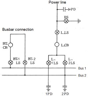
9. CT Inspection
It shall be carried out according to the inspection items specified separately in Article29if it is necessary.
10. Sequence and Interlock Tests
A breaker of line, a breaker of busbar connection and a disconnecting switch shall satisfy the interlock conditions of breaker and disconnecting switch, and they are shown in the following figure and table.
Figure 31-2 Example of single-line diagram for substation
Table 31-1 Interlock conditions
Operation |
Conditions |
|
|
L.LS ON or OFF |
L.CB (OFF) + ES (OFF) |
ES ON or OFF |
L.LS (OFF) + With NO Line Voltage |
L.1LS ON or OFF |
L.CB (OFF) + L.2LS (OFF) |
|
BT.1LS (ON) + BT.2LS (ON) + BT.CB(ON) + L.2LS (ON) |
L.2LS ON or OFF |
L.CB (OFF) + L.1LS (OFF) |
|
BT.1LS (ON) + BT.2LS (ON) + BT.CB(ON) + L.1LS (ON) |
BT.1LS ON or OFF |
BT.CB (OFF) |
BT.2LS ON or OFF |
BT.CB (OFF) |
11. Phase Check
Phase check shall be carried out for each outlet of GIS to confirm that the primary circuit connection conforms to the manufacturers’ specifications and phase arrangement of grid link.
45
12. Withstand Voltage Test
Withstand voltage test shall be carried out after installation on site if it is necessary.
The methods of withstand voltage test are as follows:
(1)Test method of IEC or Vietnamese standard (regulated for equipment individually)
(2)Test method of Japanese standard (regulated for all equipment comprehensively)
The test shall becarried out according to test |
method of IEC etcpreferentially,. and be |
carried out according to test method ofJapanese |
standard alternativelyif it is difficult to |
apply the former method.If it is uncertain about test method, test shall be carried out in consultation with manufacturer.
(1) Test method of IEC (Withstand voltage test on site for GIS regulated in IEC 62271-203)
1)Purpose
Since it is especially important for GIS, the dielectric integrity shall be checked in order to
eliminate fortuitous causes (wrong fastening, damage during handling, transportation, storage and installation, presence of foreign bodies, etc.) which might in the future give rise
to an internal fault.
Normally the withstand voltage test shall be made after the GIS has been fully installed and gas-filled at the rated filling density preferably at the end of all site tests, when newly installed.
A detailed test program for thewithstand voltage tests on site shall be agreed between manufacturer and user.
2)Test procedures
(a)Preparation before test
The GIS shall be installed completely and gas-filled at its rated filling density.
Some parts may be disconnected for the test, either because of their high charging current or because of their effect on voltage limitation, such as
-High voltage cables and overhead lines;
-Power transformers and, occasionally, voltage transformers;
-Surge arresters and protective spark gaps.
(b) Detailed |
above |
matters shall |
be |
decided between manufacturer |
and |
user. |
||
Test procedures |
|
|
|
|
|
|
|
|
One of the following test procedures shall be chosen to check that no abnormality |
|
|||||||
exists in GIS. |
|
|
|
|
|
|
|
|
Procedure |
A |
(recommended |
for |
nominal |
voltage |
110kV |
and |
below |
Power-frequency voltage test for the duration of 1 minuteat the value Uds |
specified |
|
|
|||||
in Table 31-3, Column 3. |
|
|
|
|
|
|
||
Procedure B (recommended for nominal voltage 220kV and above)
-Power-frequency voltage test for the duration of 1 minute at the value Uds specified in Table 31-3, Column 3;
46
- And partial discharge (PD) measurements according to Table 31-3, however with Upre-stress = Uds of Table 31-3 Column 3.
Procedure C (recommended for nominal voltage 220kV and above, alternative to procedure B)
-Power-frequency voltage test for the duration of 1 minute at the value Uds specified in Table 31-3, Column 3;
-And lightning impulse tests with three impulses of each polarity and with the value Ups specified in Table 31-3, Column 4.
|
Table 31-2 Test voltage for measuring PD intensity |
|
|
|
||||||
|
|
|
|
|
|
|
|
|
||
|
System with solidly earthed neutral |
|
System without solidly earthed |
|
|
|
||||
|
|
neutral |
|
|
|
|||||
|
|
|
|
|
|
|
||||
|
Pre-stress |
Test voltage for PD |
|
Pre-stress voltage |
|
Test voltage for |
|
|
||
|
voltage |
measurement |
|
Upre-stress |
|
|
PD measurement |
|
|
|
|
Upre-stress |
Upd-test |
|
|
|
Upd-test |
|
|
|
|
|
(1 minute) |
(>1 minute) |
|
(1 minute) |
|
|
(>1 minute) |
|
|
|
Single-phase |
|
|
|
|
|
|
|
|
|
|
enclosures |
|
|
|
|
|
|
|
|
|
|
design |
Upre-stress = Uds |
Upd-test = 1.2Ur / √3 |
|
Upre-stress = Uds |
|
|
Upd-test = 1.2Ur |
|
|
|
(phase-to- |
|
|
|
|
|
|||||
|
|
|
|
|
|
|
|
|
|
|
earth |
|
|
|
|
|
|
|
|
|
|
voltage) |
|
|
|
|
|
|
|
|
|
|
Three-phase |
Upre-stress = Uds |
Upd-test, ph-ea = 1.2Ur |
|
Upre-stress = Uds |
|
|
Upd-test, ph-ea = 1.2Ur |
|
|
|
enclosures |
/√3 |
|
|
|
|
|
||||
design |
|
Upd-test, ph-ph = 1.2Ur |
|
|
|
|
|
|
|
|
|
|
|
|
|
|
|
|
|
|
|
Ur: Rated highest voltage for equipment as per Table 31-3. |
|
|
|
|
|
|
||||
Uds: Power-frequency withstand test voltage as per Table 31-3. |
|
|
|
|
|
|
||||
Upre-stress: Pre-stress voltage. |
|
|
|
|
|
|
|
|
|
|
Upd-test: Test voltage for PD measurement. |
|
|
|
|
|
|
|
|
||
Upd-test, ph-ea: Test voltage for PD measurement, phase-to-earth. |
|
|
|
|
|
|
||||
Upd-test, ph-ph: Test voltage for PD measurement, phase-to-phase. |
|
|
|
|
|
|
||||
3) Partial discharge test procedure |
|
|
|
|
|
|
|
|
||
The applied power-frequency voltage is raised to a prestress- |
value (Upre-stress) which is |
|
||||||||
identical to the power-frequency withstand |
voltage test and |
maintained at that |
value |
for |
||||||
1 minute. Partial discharges occurring during this period shall |
be disregarded. |
Then, |
the |
|||||||
voltage is decreased to a specific valueUpd( -test) defined in Table31-3 depending on the |
|
|||||||||
configuration of equipment and system neutral for partial discharge measurement. |
|
|
|
|||||||
In addition, all components shall be tested in accordance with their relevant standards.
4)Maximum permissible partial discharge intensity
The maximum permissible partial discharge level shall not exceed 5pC of the test voltage specified in Table 31-3.
The values stated above applies to individual components as well as to the sub-assemblies in which they are contained. However, some equipment, such as voltage transformers isolated with liquid, immersed or solid, have an acceptable level of partial discharge in accordance
47

with their relevant standard more than 5pC. Any sub-assembly containing components with a permitted partial discharge intensity more than 5pC shall be considered acceptable if the
discharge level does not exceed 10pC. Components for which higher levels are accepted shall be tested individually and are not integrated to the sub-assembly during test.
|
Table 31-3 |
On site test voltages |
|
||
|
|
|
|
|
|
Nominal voltage |
Highest voltage |
On-site short- |
On-site lightning |
Rated lightning |
|
of system |
for equipment |
duration power- |
impulse |
impulse |
|
|
|
frequency |
withstand |
withstand |
|
Un |
Ur |
|
withstand |
voltage |
voltage |
|
voltage |
1.2/50μs |
1.2/50μs |
||
kV (r.m.s.) |
kV (r.m.s.) |
|
Uds |
Ups |
Up |
|
|
kV (r.m.s.) |
kV (peak value) |
kV (peak value) |
|
[1] |
[2] |
|
[3] |
[4] |
[5] |
|
|
|
165 |
360 |
450 |
110 |
123 |
|
200 |
440 |
550 |
|
|
|
|
|
|
|
|
|
310 |
680 |
850 |
220 |
245 |
|
345 |
760 |
950 |
|
|
|
380 |
840 |
1,050 |
500 |
550 |
|
560 |
940 |
1,240 |
|
|
|
|
|
|
Note : - The on-site test voltages have |
been calculated as follows: |
|
|||
Uds (on-site test value) = Up × 0.45 × 0.8 (column [3]) |
|
||||
Ups (on-site test value) = Up × 0.8 |
(column [4]) |
|
|
||
- All values have been rounded up to the next higher modus 5 kV. - Frequency is from 10 to 300Hz
(2) (Reference) Test method of Japanese standard The details are specified in item 11 of article 27.
Article 32. The inspection item for Vacuum Circuit Breaker (VCB)
1. Visual Inspection
It shall be checked whether VCB has abnormalities such as gas leakage, crack, breakage, damage, looseness at screwed parts, etc. or not.
2. Measurement of Insulation Resistance
It shall be carried out according to the inspection items specified separately in Article 30.
3. Measurement of Contact Resistance for Direct Current
It shall be carried out according to the inspection items specified separately in Article 30.
4. Opening and Closing Operations Test
It shall be carried out according to the inspection items specified separately in Article 30.
5. Measurement of Opening and Closing Characteristics
It shall be carried out according to the inspection items specified separately in Article 30.
48
6. Associated Tank Capacity
It shall be carried out according to the inspection items specified separately in Article 30.
7. Interlocking System Test
It shall be carried out according to the inspection items specified separately in Article 30.
8. Operation Test of Safety Valve
It shall be carried out according to the inspection items specified separately in Article 30.
9. Bushing CT Inspection
It shall be carried out according to the pectionins items specified separately in Article29 if it is necessary.
10. Withstand Voltage Test
Withstand voltage test shall be carried out after installation on site if it is necessary.
The methods of withstand voltage test are as follows:
(1)Test method of IEC or Vietnamese standard (regulated for equipment individually)
(2)Test method of Japanese standard (regulated for all equipment comprehensively)
The test shall becarried out according to test method of IEC etcpreferentially,. and be carried out according to test method ofJapanese standard alternatively if it is difficult to apply the former method.If it is uncertain about test method, test shall be carried out in consultation with manufacturer.
(1)Test method of IEC (power frequency test for current tansformer regulated in IEC60694) The details are specified in item 11 of article30.
(2)(Reference) Test method of Japanese standard
The details are specified in item 11 of article27.
Article 33. The inspection item for Oil Circuit Breaker (OCB)
1. Visual Inspection
It shall be checked whether OCB has abnormalities such as oil leakage, crack, breakage, damage, looseness at screwed parts, etc. or not.
2. Measurement of Insulation Resistance
It shall be carried out according to the inspection items specified separately in Article 30.
3. Measurement of Contact Resistance for Direct Current
It shall be carried out according to the inspection items specified separately in Article 30.
4. Opening and Closing Operations Test
It shall be carried out according to the inspection items specified separately in Article 30.
5. Measurement of Opening and Closing Characteristics
It shall be carried out according to the inspection items specified separately in Article 30.
49
6. Insulation Oil Test
Insulation performance of OCB oil shall be checked to confirm that the performance complies with the standards shown in Table 33
Table 33 Main characteristics of OCB oil for new OCB after filling
|
|
(IEC60422) |
Property |
Nominal voltage |
Standards |
|
|
|
Breakdown voltage |
More than 72.5kV |
More than 40 |
(kV/2.5mm) |
72.5kV and less |
More than 30 |
7. Associated Tank Capacity
It shall be carried out according to the inspection items specified separately in Article 30.
8. Interlocking System Test
It shall be carried out according to the inspection items specified separately in Article 30.
9. Operation Test of Safety Valve
It shall be carried out according to the inspection items specified separately in Article 30.
10. Bushing CT Inspection
It shall be carried out according to the inspection items specified separately in Article29if it is necessary.
11. Withstand Voltage Test
Withstand voltage test shall be carried out after installation on site if it is necessary.
The methods of withstand voltage test are as follows:
(1)Test method of IEC or Vietnamese standard (regulated for equipment individually)
(2)Test method of Japanese standard (regulated for all equipment comprehensively)
The test shall becarried out according to test method of IEC etcpreferentially,. and be carried out according to test method ofJapanese standard alternatively if itis difficult to apply the former method.If it is uncertain about test method, test shall be carried out in consultation with manufacturer.
(1)Test method of IEC (power frequency test for current transformers regulated in IEC60694) The details are specified in item 11 of article30.
(2)(Reference) Test method of Japanese standard
The details are specified in item 11 of article27.
Article 34. |
The inspection item for disconnector |
|
1. |
Visual Inspection |
|
It |
shall be |
checked whether disconnector has abnormalities such as crack, breakage, damage, |
looseness at screwed parts, etc. or not.
50
2. Measurement of Insulation Resistance
It shall be carried out according to the inspection items specified separately in Article 30.
3. Measurement of Contact Resistance for Direct Current
It shall be carried out according to the inspection items specified separately in Article 30.
4.Opening and Closing Operations Test
(1)Manual opening and closing operations test
It shall be checked that there is no abnormality in disconnector by opening and closing it three times by manual handle or press button in the field.
(2)Opening and closing operations test by remote control
It shall be checked that there is no abnormality indisconnector by opening and closing it three times at the rated voltage (pressure) by remote control.
5.Interlock Tests
It shall be carried out according to the inspection items specified separately in Article 31.
6. Withstand Voltage Test
Withstand voltage test shall be carried out after installation on site if it is necessary.
The methods of withstand voltage test are as follows:
(1)Test method of IEC or Vietnamese standard (regulated for equipment individually)
(2)Test method of Japanese standard (regulated for all equipment comprehensively)
The test shall becarried out according to test method of IECtce. preferentially, and be carried out according to test method ofJapanese standard alternatively if it is difficult to apply the former method.If it is uncertain about test method, test shall be carried out in consultation with manufacturer.
(1)Test method of IEC (power frequency test for current transformer regulated in IEC60694) The details are specified in item 11 of article30.
(2)(Reference) Test method of Japanese standard
The details are specified in item 11 of article27.
Article 35. The inspection item for air compressor
1. Visual Inspection
It shall be checked whether the air compressor has abnormalities such as air leakage, crack, breakage, damage, looseness at screwed parts, etc. or not.
2. Safety Valve Test
It shall be confirmed the safety valve operates before the air or oil pressure rises to the maximum allowable pressure of a tank. Operating pressure and reset pressure shall be measured to confirm that the measured value is within the manufacturers’ standards.
51

3. Automatic Start and Stop Test
It shall be confirmed tha the compressor shall automatically start at the starting pressure and stop at the stopping pressure. Starting and stopping pressure shall be measured to confirm that the measured value is within the manufacturers’ standards.
4.Air Pressure alarm Test
(1)Air pressure that detectors are activated for high and low pressure alarm
It shall be checked that detectors are activatedfor high and low pressure alarm by changing the pressure. The activation pressure shall bewithin the manufacturers’ standards and meet the relation of pressure as below.
Operation lock pressure < Low alarm pressure <
High alarm pressure < Safety valve operating pressure
(2)Air pressure that alarms are reset
It shall be checked that high and low alarms are resetchangingby the pressure. Thereset pressure shall be within the manufacturers’ standards.
Article 36. The inspection item for compact switch gear cubicle
1. Visual Inspection
It shall be checked whether the compact switch gear cubicle has abnormalities such as crack, breakage, damage, looseness at screwed parts, etc. or not.
2. Measurement of Insulation Resistance
It shall be carried out according to the inspection items specified separately in Article 30.
3.Sequence and Interlock Tests
(1)Sequence test of distribution cubicle control boards
Sequence test shall be carried out to confirm that the control circuits conform to the design diagram.
(2) Interlock test of distribution cubicle control boards
Interlock test shall be carried out to confirm that both electrical and mechanical interlocks conform to the procurement specifications.
4. Phase check
Phase check shall be carried out to confirm that the phase arrangement of equipment and primary circuit connection conform to the design diagram.
The test procedure is as below.
--All of the grounding points of equipment shall be disconnected.
--Only testing phase shall be grounded and the other 2 phases shall be ungrounded.
--It shall be confirmed that the insulation resistance between the testing phase and the ground is 0, and those of other 2 phases are not 0.
--All 3 phases shall be checked in these ways.
52
5. Withstand Voltage Test
Withstand voltage test shall be carried out after installation on site if it is necessary.
The methods of withstand voltage test are as follows:
(1)Test method of IEC or Vietnamese standard (regulated for equipment individually)
(2)Test method of Japanese standard (regulated for all equipment comprehensively)
The test shall becarried out according to test method of IEC etcpreferentially,. and be carried out according to test method ofJapanese standard alternatively if it is difficult to apply the former method.If it is uncertain about test method, test shall be carried out in consultation with manufacturer.
(1)Test method of IEC etc. (Withstand voltage test on site for cubicle regulated in IEC62271-200) After erection, cubicle should be tested to check correct operation.
The test voltage is specified in Table 36, Column 3. The duration of withstand voltage test is 1 minute.
The detailed test program shall be decided between manufacturer and user.
Table 36 On site test voltages
Nominal voltage of |
Highest voltage for |
|
On-site short- |
Rated short-duration |
|
system |
|
equipment |
|
duration power- |
power-frequency |
|
|
|
|
frequency withstand |
withstand voltage |
|
|
|
|
voltage |
Ud |
Un |
|
Ur |
|
Uds |
kV (r.m.s.) |
kV (r.m.s.) |
kV (r.m.s.) |
|
kV (r.m.s.) |
|
|
|
|
|
|||
|
|
|
|
|
|
[1] |
|
[2] |
|
[3] |
[4] |
|
|
|
|
|
|
6 |
|
7.2 |
|
16 |
20 |
|
|
|
|
|
|
10 |
|
12 |
|
22.4 |
28 |
|
|
|
|
|
|
15 |
|
17.5 |
|
30.4 |
38 |
|
|
|
|
|
|
22 |
|
24 |
|
40 |
50 |
|
|
|
|
|
|
35 |
|
38.5 |
|
60 |
75 |
|
40.5 |
|
64 |
80 |
|
|
|
|
|||
|
|
|
|
||
Note : The on-site test voltages have been calculated as follows: |
|
||||
- Uds (on-site test value) = Ud × 0.8 (column [3]) |
|
||||
- Frequency is from 45 to 65Hz |
|
|
|||
|
|
|
|
|
|
(2) (Reference) Test method of Japanese standard |
|
|
|||
The details are specified in item 11 of article 27. |
|
||||
Article 37. |
The inspection item for power capacitor |
|
|||
1. Visual Inspection
It shall be checked whether the power capacitor has abnormalities such as oil leakage, crack, breakage, damage, looseness at screwed parts, etc. or not.
53
2.Measurement of Insulation Performance
(1)Insulation resistance of main circuits
Insulation resistance between maincircuits and the ground shall be measured by a 2,500V megger. Standards of the insulation resistance are in Table 37-1.
(2)Insulation resistance of control circuits
Insulation resistance of control circuits shall |
be measured by a or500V1,000V megger. |
|||
Standards of the insulation resistance are in Table 37-1. |
||||
Table 37-1 Standards of insulation resistance for power capacitor |
||||
|
|
|
|
|
|
Test object |
|
Standards (MΩ) |
|
|
Main circuit |
|
1,000 and more |
|
|
Control circuit |
|
2 and more |
|
(3)Measurement of dielectric loss
Dielectric loss angle (tan δ) shall be measured to confirm that the measured value is within the manufacturers’ standards by applying the rated voltage. The measured value shall be modified to one at standard temperature to evaluate correctly.
If the implementation of the test by applying rated voltage is difficult, it is possible to change the test conditions in consultation with the manufacturer.
3.Condenser capacity measurement
Condenser capacity shall be measured to confirm that the measured value is within the manufacturers’ standards.
4. Sequence Tests
Sequence test shall be carried out to confirm that thecontrol circuits (such as alarm circuits) conform to the design diagram.
5. Withstand Voltage Test
Withstand voltage test shall be carried out after installation on site if it is necessary.
The methods of withstand voltage test are as follows:
(1)Test method of IEC or Vietnamese standard (regulated for equipment individually)
(2)Test method of Japanese standard (regulated for all equipment comprehensively)
The test shall becarried out according to test method of IEC etcpreferentially,. and be carriedout according to test method of Japanese standard alternatively if it is difficult to apply the former method. If it is uncertain about test method, test shall be carried out in consultation with manufacturer.
54
(1)Test method of IEC
1)One of the following test procedures shall be chosen for live-tank type
(a)AC voltage test between terminals and container regulated in IEC60871-1
The conditions of applying test voltage shall refer to IEC 600601-. The test shall be implemented as follows.
-Test voltage: The voltage (Ut) calculated according to the following equation shall be applied
Ut = 2.5 × Un × n
where
Ut is the power-frequency test voltage Un is the rated voltage of the capacitor
n is the number of units in series relative to the electrical potential to which the containers are connected.
- Duration of test is 10 seconds.
(b)DC voltage test between terminals regulated in IEC60871-1 The test shall be implemented as follows.
-Test voltage: The voltage (Ut) calculated according to the following equation shall be applied
Ut = 4.0 × Un × n × 0.75
where
Ut is the power-frequency test voltage Un is the rated voltage of the capacitor
n is the number of units in series relative to the electrical potential to which the containers are connected.
-Duration of test is 10 seconds.
2)One of the following test procedures shall be chosen for dead-tank type
(a) AC voltage test (capacitors in single phase system) regulated in IEC60871-1
The conditions of applying test voltage shall refer to IEC 600601-. The test voltage is specified inTable 37-2, Column 2. The duration of withstand voltage test is 10 seconds
55

|
Table 37-2 |
On site test voltages |
|
|
|
|
|
|
|
Highest voltage for |
On-site short-duration |
|
Rated short-duration power- |
|
power-frequency withstand |
|
|||
equipment |
|
frequency withstand voltage |
||
|
voltage |
|
||
Ur |
|
|
Ud |
|
|
Uds |
|
||
kV (r.m.s.) |
|
|
kV (r.m.s.) |
|
kV (r.m.s.) |
|
|||
|
|
|
||
[1] |
|
[2] |
|
[3] |
1.2 |
|
4.5 |
|
6 |
|
|
|
|
|
2.4 |
|
6 |
|
8 |
|
|
|
|
|
3.6 |
|
7.5 |
|
10 |
|
|
|
|
|
7.2 |
|
15.0 |
|
20 |
|
|
|
|
|
12 |
|
21 |
|
28 |
|
|
|
|
|
17.5 |
|
28.5 |
|
38 |
|
|
|
|
|
24 |
|
37.5 |
|
50 |
|
|
|
|
|
36 |
|
52.5 |
|
70 |
|
|
|
|
|
Note :
- The on-site test voltages have been calculated as follows: Uds (on-site test value) = Ud × 0.75 (column [2])
- Frequency is from 45 to 65Hz
(b)DC voltage test between terminals regulated in IEC60871-1 The details are specified in item (1)-1)-(b) of this item.
(2)(Reference) Test method of Japanese standard
The details are specified in item 11 of article 27.
Article 38. The inspection item for surge arrester
1. Visual Inspection
It shall be checked whether the surge arrester has abnormalities such as crack, breakage, damage, looseness at screwed parts, etc. or not.
2. Measurement of Insulation Resistance
Insulation resistance between pole and ground shall be measured by a 2,500Vmegger. Standards of the insulation resistance are according to manufacturer.
3. Measurement of leakage current
Measurement of leakage current is an effective inspection method to detect moisture absorptiorn performance deterioration of inner component of a surge arrester. Leakage current shall be measured by applying the rated voltage with the rated frequency to each phase. It shall be confirmed that the measured value is within manufacturers’ specifications. In case of measurement, the surface of surge arrester (insulator) shall be cleaned sufficiently.
56
Article 39. The inspection item for battery system
1. Visual Inspection
It shall be checked whether the battery system has abnormalities such as electrolyte leakage, ck,ra breakage, damage, looseness at screwed parts, etc. or not.
2. Measurement of Voltage |
|
The voltage for each cell shall be measured to confirm thatmeasuredthe |
value is within the |
manufacturers’ standards. The sample standards of cell voltage such as nominal voltage, floating charge voltage and equalizing charge voltage are shown in Table 39-1.
Table 39-1 Sample standards of cell voltage
|
|
|
|
(V/cell) |
|
Category |
Electrode type |
Nominal voltage |
Floating charge |
Equalizing |
|
voltage |
charge voltage |
||||
|
|
|
|||
Alkaline |
1.20 |
1.40 - 1.44 |
1.55 - 1.65 |
||
battery |
Sintered |
1.20 |
1.35 |
1.50 |
|
Lead acid |
Pasted (Flat) |
2.00 |
2.15 - 2.23 |
2.30 |
|
battery |
Tubular (Clad) |
2.00 |
2.15 |
2.30 |
The test procedure and standards of cell voltage shall comply with the manufactures' specifications.
3. Equalizing charge test
Equalizing charging test shall becarried out to correct unbalanced voltage and liquid density and homogenize the upper and lower layer of electrolytes. The test procedure shall comply with the manufacturers’ specifications. After equalizing charge test, the voltage for each cell shall be measured
to confirm that the measured value is within the manufacturers’ standards.
4. Measurement of specific gravity |
|
|
|||
Only the electrolyte of lead acid battery is relevant.The specific |
gravity of electrolytefor each cell |
||||
shall be measured to confirm that the measured valueis within |
the manufacturers’ standards. The |
||||
sample standards of specific gravity of electrolyte are shown in Table 39-2. |
|||||
|
Table 39-2 |
Sample standards of specific gravity of electrolyte |
|||
|
|
|
|
|
|
|
Category |
|
Electrode type |
|
Specific gravity |
|
|
(At full charged, 20 oC) |
|||
|
|
|
|
||
|
Lead acid battery |
|
Pasted (Flat) |
|
1.24 |
|
|
Tubular (Clad) |
|
1.215 |
|
|
|
|
|
||
The test procedure and standards of specific gravity of electrolyte shall comply with the manufactures' specifications.
As the measured value will change according to the temperature, it shall be modified as below.
57
S20 = St + 0.0007 ( t - 20 )
S20 : specific gravity of electrolyte at 20 oC St : specific gravity of electrolyte at t oC
t : temperature when measurement was carried out
Article 40. The inspection item for protective relays and control equipment
1. Unit Test
Performance and characteristic tests cited below shall be carried out for each meter and relay to confirm that the measured value is within the manufacturers’ standards. The operating value shall be
set for relays. In principal, these unit tests shall be carried out with relay circuits for open and close command signals as well as CT and PT circuits being completely separated.
(1)Meter calibration
Meter calibration error of indicator shall be measured to confirm that measuredthe value is within the criterion which is made from the summation of the rated error range of indicator and the one of test equipment.
(2)Measurement of relay operate value Relay operate value shall be measured.
(3)Measurement of voltage and current characteristic
Operating voltage or current of relay shall be measured at setting conditions defined by manufacturers etc.
(4)Measurement of phase characteristic
Operating phase of relay shall be measured at setting conditions defined by manufacturers etc.
(5)Measurement of operating time
Operating time of relay shall be measured by changing relay input such as voltage, current and phase from steady to fault suddenly.
2.DC Circuit Test
(1)DC sequence test
By operating the auxiliary relayswith applying the voltage to DC circuits, it shall be checked that the control circuits meet the design diagram.
(2)Measurement of Insulation resistance
Insulation resistance of control circuits shall be measured by a 500V megger. Standards of the insulation resistance are in Table 40.
Table 40 Standards of insulation resistance for protective relays and control equipment
Test object |
Standards (MΩ) |
|
|
Control circuit |
2 and more |
|
|
(3)Load measurement
Electric power consumption shall be calculated from measured current by applying the rated control voltage. It shall be confirmed that the calculated value is within the manufacturers’
58
standards.
3.AC Circuit Test
(1)Secondary circuit test
1)Measurement of Insulation resistance
It shall be carried out according to the inspection items specified separately in2.(2) of this article.
2)Load measurement
Electric power consumption shall be calculated from measured current or voltage by applying the rated voltage or current to PT or CT circuits. It shall be confirmed that the calculated value is within the manufacturers’ standards.
(2) AC circuit test (Simulation test)
1)Fault simulation test
Operation characteristics of relay shall be checked by changing relay input from steady to
fault suddenly. In |
case of test, relay operation |
includingutomatic |
reclosing |
shall |
be |
||||
checked |
by |
simulating |
short |
circuits |
or |
ground |
faults |
at |
setting |
Operating time of relay shall also be measured by changing relay input from steady to fault suddenly. In case of measurement, the time until tripping command and automatic reclosing command sent out after changing relay input shall be measured. In addition, indications on relevant equipment shall be checked.
2)Operational simulation test
Operation of automatic operating equipment shall be checked.
4.Counter Test
AC Circuit Test (simulation) shall be carried out for equipment and transmission channelswhich are installed in two or more electric-supply stations and exchange information with one another. nI case of test, the comprehensive operations combined with related equipment shall be checked by applying the imitation input at each electric-supply station. The test contents and the check items are specified separately in 3.(2) of this article.
5. Comprehensive Test
It shall be carried out in actual operation conditions in which the switchboard is connected with related equipment by control cable.
(1)Measurement of insulation resistance
Comprehensive insulation resistance of principal and relevant systems and field equipment
including connecting terminals shall be measured. It shall be carried out according to the inspection items specified separately in 2.(2) of this article.
(2)Field equipment open and close operation test
It shall be checked that open and close command signals from control systems operate only intended field equipment and cause no abnormality.
(3)Interlock test
Field equipment shall be checked to properly operate corresponding to interlock conditions.
59
(4)Protection relay operation and alarm indication test
It shall be checked that protection relays and controlsystems are properly connected to primary
equipment, and that fault |
indication and alarm as well as |
operation of |
relevant equipment |
properly correspond to the relay or control system operation. |
|
|
|
6. Comprehensive Test with PT Circuits |
|
|
|
It shall be carried outn i actual |
operation conditions in which the |
switchboard |
is connected with |
related equipment by control cable.
(1) Measurement of insulation resistance
It shall be checked with earth circuits being disconnected that comprehensive circuits including
PT, control cables and distribution boards are properly insulated (with no short circuits or ground faults). It shall be carried out according to the inspection items specified separately in 2.(2) of this article..
(2) Polarization test
It shall be checked thatthe secondary circuit of PT thatis connected with control cable conforms to the design.
(3) Transforming ratio test
By applying voltage to the primary circuit of PT, voltage and phase angle shall be measured at PT test terminals in distribution boards that are connectedto the secondary (tertiary) circuitof
PT in order to check that transforming ratio and connection between the PT and distribution board are proper.
(4)Load measurement
With the subject PT being fully loaded, the secondary circuitof PT shall be applied withthe rated voltage, and comprehensive load including distribution board and control cable shall be measured in order to check that it is the same level as design value.
(5)Simultaneous operation check
In case that transformation ratios for two or more PT aresimultaneously measured, it shall be checked that the secondary circuits of each PT are properly connected to distribution boards by rendering a knife switch or circuit breaker “Off.”
7.Comprehensive Test with CT Circuits
It shall be carried out in actual erationop conditions in which the switchboard is connected with related equipment by control cable.
(1)Measurement of insulation resistance
It shall be checked with earth circuits being disconnected that comprehensive circuits including
CT, control cables and distribution boards are properly insulated (with no short circuits or ground faults). It shall be carried out according to the inspection items specified separately in 2.(2) of this article.
(2) Polarization test
It shall be checked thatthe secondary circuit of CT thatis connected with control cable conforms to the design.
60