

Section 3 Underground Transmission Line
Article 18. Inspection of cable joint boxes
The connection box and terminal box of the cable line shallsatisfy inspection items in the following table.
Table 18 Inspection of connection box and terminal box
Items |
Method |
Acceptance criteria |
|
|
|
|
|
|
|
- Insulation resistance between each core of the |
|
|
|
cable and the ground shall be confirmed by |
|
|
|
megger. In addition, insulation resistance between |
|
|
|
cores of multiple cores cable (except cables with |
|
|
|
shielding layer) which each core is insulated |
|
|
|
mutually shall be confirmed. |
|
Insulation resistance |
Measurement |
- The value measured at one minute after the |
|
measurement was started shall basically be |
|||
|
|
adopted. In case that the value is not stable, it |
|
|
|
should be measured after the value becomes |
|
|
|
stable. |
|
|
|
- Use 2,500V megger for testing. |
|
|
|
- Air temperature and humidity at the measurement |
|
|
|
shall be recorded. |
|
|
|
- The dimensions and the construction methods of |
|
|
|
connection box and terminal box confirmed by |
|
|
|
quality and construction records shall be in |
|
Connection box |
|
accordance with the specification. In addition, all |
|
Document |
dimensions (the length of removing protective |
||
Terminal box |
|||
|
covering outer sheath, the length of exposed |
||
|
|
shielding layer and the length of penciling of |
|
|
|
insulation material, etc.) of connection box and |
|
|
|
terminal box shall be within permissible values. |
|
Straightness of cable |
Document |
- Straightness of cable straightened by heat shall be |
|
in accordance with the specification. |
|||
|
|
||
|
|
- The cable shall be marked before it is inserted into |
|
|
|
the transformer equipment. The distance from the |
|
Insertion of terminal |
|
bottom plate of equipment to marking on the |
|
|
cable shall be in accordance with the specification |
||
box of slip-on type |
|
||
Measurement |
after the insertion. (Refer to Figure ure 18) |
||
(Only EB-GS and |
|||
|
- Inserted cable shall be checked to ensure the |
||
EB-OS) |
|
appropriate insertion by hearing and touching by |
|
|
|
the construction worker in the event of the |
|
|
|
insertion. |
7
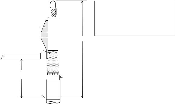
Stress cone
Conductive coating Bottom plate
Y
Marking
Z : The distance of marking is from the cable Marking at the distance: Z from the cable
terminalterminaltop endandtomeasurthe markingthe pointdistance:. Y
from the bottom plate to the marking
Y : The distance of measuring is from the bottom enable a secure insertion of the conductor.
plate of equipment to the marking point.
Z
 Outer semi-conductive layer
 Cloth tape
Shielding layer
Sheath
Figure 18 (Reference drawing) Insertion of terminal box of slip-on type
Article 19. Phase check
Phases of the cable shall satisfy inspection items in the following table.
Table 19 Inspection of phase of cable
Items |
Method |
Acceptance criteria |
|
|
|
|
|
- The same phase of both ends of the cable shall |
|
|
satisfy following conditions. |
|
|
(1) When one end of the cable is attached the |
|
|
grounding, the value of insulation resistance |
|
|
between the phase and the ground which |
Phase |
Measurement |
measured at opposite end is 0 Ω. |
|
|
(2) When one end of the cable is removed from the |
|
|
grounding, the value of insulation resistance |
|
|
between the phase and the ground which |
|
|
measured at opposite end increases. (more than |
|
|
0 Ω) |
|
|
|
Article 20. Earth connection
Grounding conductors of the cable and metallic parts shall satisfy inspection items in the following table.
8
Table 20 Inspection of grounding conductor of cable and metallic parts
Items |
Method |
Acceptance criteria |
|
|
|
|
|
Value of grounding |
|
- The value of grounding resistance shall be less or |
|
Measurement |
equal to the value shown in chapter 6 in Technical |
||
resistance |
|||
|
Regulation Vol.1. |
||
|
|
|
|
|
|
- Kind, nominal cross sectional area and buried |
|
|
|
situation of the grounding conductor and the |
|
Conditions |
Visual inspection |
condition of the terminal part of the grounding |
|
|
|
conductor shall be in accordance with the |
|
|
|
specification. |
Article 21. Conditions of cable supporters
Cable supporters (cable rack, etc.) shall satisfy inspection items in the following table.
Table 21 Inspection of cable supporter
Items |
Method |
Acceptance criteria |
|
|
|
|
|
- Number and fixed position of cable supporters |
|
|
shall be in accordance with the specification. |
Conditions |
Visual inspection |
- Cable supporters shall not be damaged or |
|
|
corroded, and bolts of the supporters shall not be |
|
|
loose. |
Article 22. Cable installation
The cable at the laying work shall satisfy inspection items in the following table.
9
Table 22-1 Inspection of cable
Items |
Method |
Acceptance criteria |
|
|
|
|
|
|
|
- Kind, nominal cross sectional area and number of |
|
Conditions |
Visual inspection |
cables shall be in accordance with the |
|
specification. |
|||
|
|
||
|
|
- The cable shall not be damaged. |
|
|
|
- Tension of cable laying shall be less or equal to |
|
Tension of cable |
|
the permissible tension of cable laying. |
|
Measurement |
- Permissible tension 68.6×N×A (N) |
||
laying |
|||
|
N : Number of cores of cable |
||
|
|
||
|
|
A : Cross sectional area of cable (mm2) |
|
|
|
- The value of cable lateral pressure calculated by |
|
|
|
the tension of cable laying shall be less or equal to |
|
Cable lateral pressure |
Document |
the value of permissible cable lateral pressure. |
|
|
|
- Permissible cable lateral pressure is shown in |
|
|
|
Table 22-2. |
|
|
|
- Bending radius of cable shall be more than the |
|
|
|
permissible bending radius shown in Table 22-3. |
|
Bending radius |
Measurement |
However, bending radius at the construction work |
|
|
|
shall be 1.5 times more than the permissible |
|
|
|
bending radius. |
Table 22-2 Permissible cable lateral pressure
|
Kind of cable |
|
Permissible cable lateral pressure (N/m) |
||
|
|
|
|
|
|
Oil-filled |
Aluminium sheath |
Single core |
|
2,940 |
|
cable |
Triple cores |
|
2,940 |
||
|
|
||||
|
No metallic sheath |
Single core |
|
2,940 |
|
XLPE |
Triple cores |
|
2,450 |
||
|
|
||||
cable |
Aluminium sheath |
Single core |
|
2,940 |
|
|
Stainless sheath |
Single core |
|
2,940 |
|
|
Table 22-3 Permissible bending radius |
|
|
||
|
|
|
|
|
|
|
|
|
Permissible bending |
Permissible bending |
|
|
Kind of cable |
|
radius at construction |
||
|
|
radius (m) |
|
||
|
|
|
|
work (m) |
|
|
|
|
|
|
|
|
|
|
|
|
|
Oil-filled |
Aluminium sheath |
Single core |
15×(Cable diameter) |
|
22.5×(Cable diameter) |
|
12×(Average twisted |
|
18×(Average twisted |
||
cable |
Triple cores |
|
|||
|
diameter) |
|
diameter) |
||
|
|
|
|
||
|
No metallic sheath |
Single core |
10×(Cable diameter) |
|
15×(Cable diameter) |
XLPE |
Triple cores |
8×(Average twisted |
|
12×(Average twisted |
|
|
diameter) |
|
diameter) |
||
cable |
|
|
|
||
Aluminium sheath |
Single core |
15×(Cable diameter) |
|
22.5×(Cable diameter) |
|
|
|
||||
|
Stainless sheath |
Single core |
17.5×(Cable diameter) |
|
26.3×(Cable diameter) |
Remark : If the cable specification exceeds the above value, the specification shall be applied.
10
Article 23. Insulation resistance of cable jacket
Insulation resistance of protective covering outer sheath shall satisfy inspection items in the following table.
The inspection time shall be after laying the cable and before shielding layerattachedis to the grounding conductor.
Table 23-1 Inspection of insulation resistance of protective covering outer sheath
|
Items |
|
Method |
|
Acceptance criteria |
||
|
|
|
|
|
|
|
|
|
|
|
|
|
|
- The value of insulation resistance of protective |
|
|
|
|
|
|
|
covering outer sheath (between shielding layer |
|
|
|
|
|
|
|
and the ground) shall be more than the value of |
|
|
|
|
|
|
|
permissible insulation resistance shown in |
|
|
Insulation resistance |
|
|
|
|
Table 23-2. |
|
|
of protective |
|
Measurement |
|
- The value measured at one minute after the |
||
|
covering outer sheath |
|
|
|
measurement was started shall basically be |
||
|
|
|
|
adopted. In case that the value is not stable, it |
|||
|
|
|
|
|
|
||
|
|
|
|
|
|
should be measured after the value becomes |
|
|
|
|
|
|
|
stable. |
|
|
|
|
|
|
|
- - Use 1,000V or 2,500V megger for testing. |
|
|
|
|
|
|
|
|
|
|
Table 23-2 |
Permissible insulation resistance of protective covering outer sheath |
|||||
|
|
|
|
|
|
|
|
|
Kind of cable |
|
|
Permissible insulation resistance of |
|
||
|
|
protective covering outer sheath (Ω-km) |
|
||||
|
|
|
|
|
|
||
|
XLPE cable |
|
10 × 106 |
|
|||
|
Oil-filled cable |
|
10× 106 |
|
|||
Article 24. Cable snaking
Snaking installation of the cable shall satisfy inspection items in the following table.
Table 24 Inspection of snaking installation
Items |
Method |
Acceptance criteria |
|
|
|
|
Measurement |
- Length and width of snaking installation shall be |
|
in accordance with the specification. |
|
|
|
|
|
|
|
Conditions of |
|
- Number and position of the fixed parts for snaking |
|
installation shall be in accordance with the |
|
snaking installation |
Visual inspection |
specification. |
|
- The fixed parts for snaking installation shall not |
|
|
|
|
|
|
be damaged or corroded, and bolts shall not be |
|
|
loosened. |
Article 25. Grounding points
Grounding conductor of the connection box and the terminal box shall satisfy inspection items in the following table.
11
Table 25 Inspection of grounding conductor of connection box and terminal box
Items |
Method |
Acceptance criteria |
|
|
|
|
|
|
|
- Grounding methods (cross-bonding method, etc.) |
|
Grounding method |
Visual inspection |
of connection boxes and terminal boxes shall be in |
|
|
|
accordance with the specification. |
|
Value of grounding |
|
- The value of grounding resistance shall be less or |
|
Measurement |
equal to the value shown in chapter 6 in Technical |
||
resistance |
|||
|
Regulation Vol.1. |
||
|
|
|
|
|
|
- Kind, nominal cross sectional area and buried |
|
|
|
situation of the grounding conductor and the |
|
Conditions |
Visual inspection |
condition of the terminal part of the grounding |
|
|
|
conductor shall be in accordance with the |
|
|
|
specification. |
Article 26. |
Clearance from other cables, pipes, etc |
||||
Offset distance |
from |
the cable to other |
lines and pipe lines shall ysatiinsfpection items in the |
||
following table. |
|
|
|
|
|
Table 26 Inspection of offset distance from the cable to other lines and pipe lines |
|||||
|
|
|
|
|
|
Items |
|
Method |
|
Acceptance criteria |
|
|
|
|
|
|
|
|
|
|
|
- The offset distance from the cable to other lines |
|
Offset distance |
Measurement |
|
and pipe lines shall be more or equal to the |
|
|
|
distance shown in Chapter 3-2 in Technical |
|
|||
|
|
|
|
|
|
|
|
|
|
Regulation Vol.1. |
|
|
|
|
|
|
|
|
|
|
|
- Number and position of the protective measure for |
|
Conditions |
|
Visual inspection |
|
the cable, other lines and pipe lines shall be in |
|
|
|
|
|
accordance with the specification. |
|
Article 26-a1. DC high voltage test and measurement of leakage current
DC voltage test shall be implemented as follows.
(1)DC voltage test for the rated voltage from 1kV to 30kV (IEC 60502-1)
-Test voltage is shown in the Table 26-a1-1
-Duration of test is 15 minutes.
12
Table 26-a1-1 DC voltage test for cables rated voltage from 1kV up to 30kV
(IEC60502-1)
Rated voltage |
Test voltage |
||
4 U0 (kV) |
|||
U0 / U (Um) (kV) |
|||
(phase-to-ground) |
|||
|
|
||
|
|
|
|
0.6 / 1 |
(1.2) |
2.4 |
|
1.8 / 3 |
(3.6) |
7.2 |
|
3.6 / 6 |
(7.2) |
14.4 |
|
6 / 10 |
(12) |
24 |
|
8.7 / 15 |
(17.5) |
34.8 |
|
12 / 20 (24) |
48 |
||
18 / 30 (36) |
72 |
||
NOTE
-U0 is the rated power frequency voltage between conductor and earth or metallicscreen for which the cable is designed.
-U is the rated power frequency voltage between conductors for which the cable is designed.
-Um is the maximum voltage of the “highest system voltage” for which the equipment may be used.
-For cables rated voltage from 1kV up to 30kV, if it is possible to implement AC voltage test, it shall be implemented by applying rated power frequency voltage U for 5 minutes instead of DC voltage test.
(2)DC voltage test for the rated voltage more than 30kV (IEEE 400.1, IEC60840, IEC62067)
1)DC voltage test of the conductor (IEEE 400.1)
-Test voltage is shown in the Table 26-a1-2
-Duration of test is 15 minutes.
Table 26-a1-2 DC voltage test for cables rated voltage more than 30kV
|
|
(IEEE 400.1) |
|
System voltage (kV) |
BIL (kV) |
Test voltage (DC, kV) |
|
(phase-to-phase) |
(phase-to-ground) |
||
|
|||
69 |
350 |
175 |
|
115 |
450 |
225 |
|
138 |
650 |
325 |
|
230 |
1,050 |
525 |
NOTE: If it is possible to implement AC voltage test, one of the following test procedures shall be chosen instead of above DC voltage test
1)-Test voltage is shown Table 26-a1-3. (frequency is between 20Hz and 300Hz)
-Duration of test is 1 hour.
2)Alternatively, voltage of Uo may be applied for 24hours.
13