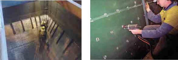
(1)Confirmation of status of erosion, corrosion and crack
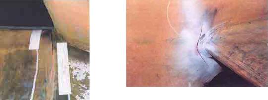
It must be confirmed that erosion, corrosion and crack at following part in steam drum. Erosion, corrosion and crack portion must be ground down andwelded when it is minor damage. It must be repaired at site by welding when it has serious damage. It must be refer to Article 167-a9 of this Guideline when welding if necessary.
1)Weld line
2)Weld part
3)Manhole
4)Vicinity of hole edge of nozzle stub
5)Tube expansion
(2)Confirmation of plugging of piping
It must be confirmed that pluingg of piping at following part relative to steam drum. Appropriate measures must be taken depending on degree of defect when detecting plugging at following part.
1)Connecting piping for water level gauge and pressure gauge etc.
2)Drain and blow piping
3)Chemical dosing piping
4)Feed water inner tube
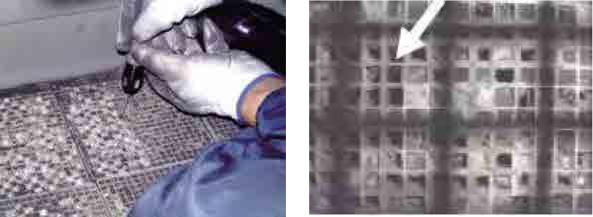
(3)Confirmation of status of deposition
It must be confirmed thatingredient and volume etc. of deposition in steam drum. It is recommended that they are analyzed chemically by specialized agency if necessaryAnalysis. results must be confirmed and appropriate measures must be taken, if necessary.
(4)Confirmation of status of seal at internal device seat face
Status of seal at internal device seal face based on status of erosion, corrosion and crack at weld part must be confirmed.
(5)Confirmation of status of mounting of internal device and defect of other parts Status of mounting of internal device and defect of other parts must be confirmed.
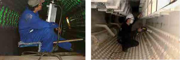
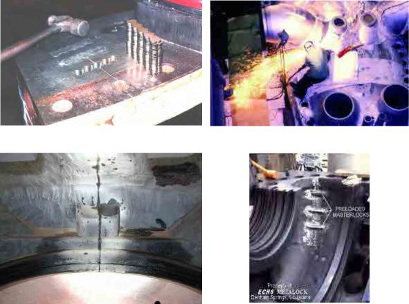
(6)MT inspection
It is recommended that inspection interval is regulated and MT inspection is conducted. (sample of inspection interval : every 8 years or 60,000 ~ 80,000 hrs)
1)MT inspection : typical of weld part of nozzle stub external surface and weld part of
longitudinal joint/circumferential joint external surface 2) MT inspection : weld part of nozzle stub inner face
(some welded internal device are disassembled : number of disassembled
3.Header (Economizer, Super-heater and Re-heater )
(1)External inspection of header and lifting ring of header.
External inspection of header and lifting ring ofheader must be conducted. When heat insulator prevents inspection, it must be disassembled.
1)Confirmation of status of erosion, corrosion and crack
It must be confirmed that erosion, corrosion and crack in header. It must be ground down and welded erosion, corrosion and crack portion when it is minor damage. It must be repaired by welding at site when it is major damage.
2)Confirmation of status of leak at weld part and tube expansion
It must be confirmed that leak at weld part and tube expansion in header. It must be taken appropriate measures depending on degree of defect when detecting defect in header.
3)Confirmation of status of crack at seat part of inspection hole
It must be confirmed that crack at seat part of inspection hole in header. It must be taken appropriate measures depending on degree of defect when detecting defect in header.
4)Confirmation of status of deposition
It must be confirmed that ingredient and volume etc. of deposition in header. It is recommended that they are analyzed chemically by specialized agency if necessary. It must be confirmed analysis results and taken appropriate measures if necessary.
(2)Internal inspection
No less than 2 typicalheaders must be selected and be conducted internal inspection to them every other periodic inspection.
252
1)Confirmation of status of erosion, corrosion and crack
It must be confirmed that erosion, corrosion and crack in header. It must be ground down and welded erosion, corrosion and crack portion when it is minor damage. It must be repaired by welding at site when it is major damage.
2)Confirmation of status of deposition
Ingredient and volume etc. of deposition in header must be confirmed. It is recommended that they are analyzed chemically by specialized agency if necessary. Analysis results and taken appropriate measures must be confirmed, if necessary.
(3)Detailed inspection
It is recommended thatPT & MT inspection are conducted after 80,000 hours of accumulated operating hours.
1) PT inspection : typical weld part of header nozzle stub and weld part of supporter
2)MT inspection : typical weld part of header longitudinal joint/circumferential joint external surface
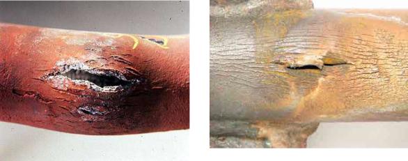
External inspection of tubes inside furnace must be conducted.
a.Confirmation of status oferosion, corrosion and crack (weld part, tube expansion and other part.)
Erosion, corrosion and crack of evaporating tubes must be confirmed. Erosion, corrosion and crack portion must be ground down and welded when it is minor damage. It must be replaced with new tube or panel when it is major damage.
253
b. Confirmation of status of tube incurve and tube swelling and disturbance of tube row
Tube incurve and tube swelling and disturbance of tube mustrow
be confirmed.
Appropriate measures must be takendepending on degree of defect
when detecting
defect at evaporating tubes.
c.Confirmation of status of deposition
Ingredient and volume etc. of deposition atevaporating tube must be confirmed. It is recommended that they areanalyzed chemically by specialized agency if necessary. Analysis results must be confirmed and appropriate measures must be taken, if necessary.
d.Confirmation of status of damage due to soot blower
Tube damage due to steam flow of soot blowermust be confirmed. Steam flow of soot blower is extremely big and there is a possibilitythat tube is worn away andleaked. Therefore, tube subject to soot blowermust be checked carefully. Appropriate measures must be taken depending on degree of defect when detecting defect at evaporating tubes.
e.Confirmation of status of ash cut
Ash-cut of evaporation tubes must be confirmed. Appropriate measures must be taken depending on degree of defect when detecting defect at evaporation tubes.
f.Confirmation of status of damage of fin, supporter, hanger etc.
Damage (burnout, crack, deformation) of fin, supporter, hanger etcmust be confirmed. Appropriate measures must be takendepending on degree of defect when detecting defect at evaporation tubes.
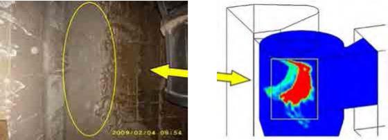
2) Visual inspection of tubes around burner.
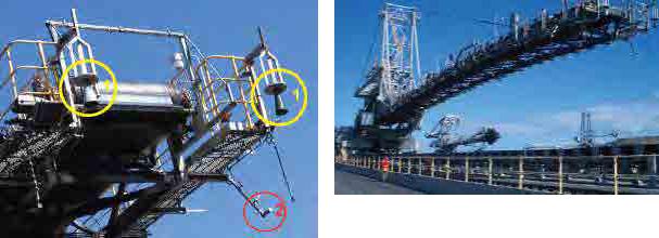
a.Visual inspection oftubes around burner byassembling scaffolding to burner level, using gondola and equivalent means every other periodic inspectionmust be conducted.
It must bepaid close attention tosafety of worker by utilizing personnel safety nets, harness etc. for high-place work.
3)Visual inspection of evaporation tube to top of furnace
a.Inspection interval must be regulated and visual inspection of evaporation tube to top of furnace must be conducted by assembling scaffolding. It must be regulated inspection interval depending on fuel, operation status of power plant etc. It must be paid close attention to safety of worker by utilizing personnel safety nets, harness etc. for -high place work.
case of no countermeasure for tube erosion must be conducted. Appropriate measures
must be taken
depending on degree of defect when radial
thickness
is
less than
acceptable value.
5)Internal inspection of water tube
a.It is recommended that inspection interval is regulated depending on operation status of power plant etc. and water tube inside is inspected to the extent possible.
254
b. Confirmation of status of deposition
Ingredient and volume etc. of deposition inside evaporation tube must be confirmed. It is recommended that they are analyzed chemically by specialized agency if necessary. Analysis results must be confirmed and taken appropriate measures must be taken if necessary.
6)Internal inspection of sample tube
a.It is recommended that inspection interval is regulated depending on operation status of power plant etc. , sample tube is picked after boiler stop and tube inside is inspected. Status of scale deposition and conducted metallographic structure inspection must be checked. Additional inspection must be conducted according to results of above inspection.
7)Detailed inspection
a.It is recommended that PT inspection is conducted to typical weld portion of connection part between tube and tube after 80,000 hours of accumulated operating hours if necessary.
Reference: P-115 of Vol.63 May/2012: Journal TEMPES
paper/
Photo 160-5 LFET inspection
Figure 160-1 Laser measuring of tube
thickness
(2)Super-heater, Re-heater and Economizer tube
1)External inspection of super-heater, re-heater and economizer tube.
External inspection of super-heater, re-heater and economizer tube must be conducted.
a.Confirmation of status of erosion, corrosion and crack (weld part, tube expansion and other part.)
Erosion, corrosion and crack of super-heater, re-heater and economizer tubes must be confirmed. Erosion, corrosion and crack portion must be ground down and welded when it is minor damage. It must be replaced with new tube or panel when it is major damage.
255
b.Confirmation of status of tube incurve and tube swelling and disturbance of tube row
Tube incurve and tube swelling and disturbance of tube row must be confirmed. Appropriate measures must be taken depending on degree of defect when detecting defect at these tubes.
c.Confirmation of status of deposition
It must be confirmed that ingredient and volume etc. of deposition at super-heater, reheater and economizer tube. It is recommended that they are analyzed chemically by specialized agency if necessary. Analysis results must be confirmed and appropriate measures must be taken, if necessary.
d.Confirmation of status of damage due to soot blower
Tube damage due to steam flow of soot blower must be confirmed. Steam flow of soot blower is extremely big and there is a possibility that tube is worn away and leaked. Therefore, tube subject to soot blower must be checked carefully. Appropriate measures must be taken depending on degree of defect when detecting defect at these tubes.
e.Confirmation of status of damage of fin, supporter, hanger etc.
Damage (burnout, crack, deformation) of fin, supporter, hanger etc. must be confirmed. Appropriate measures must be taken depending on degree of defect when detecting defect at super-heater, re-heater and economizer tubes.
2)Inspection of tube by touch.
a.Inspection of super-heater, re-heater and economizer tube must be conducted by touch in case of no countermeasure for tube erosion.
3)Measurement of radial thickness of tube.
a.Measurement of typical radial thickness of super-heater, re-heater and economizer tube must be conducted in case of no countermeasure for tube erosion. Appropriate measures must be taken depending on degree of defect when radial thickness is less than acceptable value.
4)Internal inspection of sample tube
a.It is recommended that inspection interval is regulated depending on operation status of power plant etc. , sample tube is picked after boiler stop and tube inside is inspected. Status of scale deposition must be checked and metallographic structure inspection must be conducted. It must be conducted additional inspection according to results of above inspection.
5)Detailed inspection
a.It is recommended that PT inspection is conducted to typical weld portion of connection part between tube and tube after 80,000 hours of accumulated operating hours if necessary.
256
6)Measurement of radial thickness of tube.
a.It is recommended that measurement of typical radial thickness of super-heater, re-heater tube. It must be taken appropriate measures depending on degree of defect when radial thickness is less than acceptable value.
5.Safety valve
(1)Disassembly and inspection
It must be conducted disassembly and inspection for safety valve of drum, super-heater and reheater and electric relief valve every other periodic inspection.
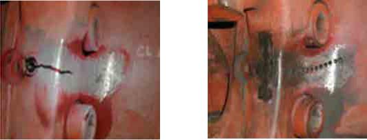
1)Confirmation of damage of valve body and valve sheet
It must be confirmed damage of valve body and valve sheet. It must be taken appropriate measures depending on degree of defect when detecting defect at safety valve.
2)Confirmation of crack of weld part
It must be confirmed crack of weld part. It must be conducted nondestructive test if necessary. It must be taken appropriate measures depending on degree of defect when detecting defect at safety valve.
3)Confirmation of foreign objects
It must be confirmed foreign objects in safety valve at disassembling and assembling. It must be assembled safety valve carefully not to mix foreign objects in safety valve.
4)Confirmation of curvature of valve stem and abrasion of stem edge
It must be confirmed curvature of valve stem and abrasion of stem edge at disassembling and assembling. It must be assembled safety valve carefully not to mix foreign objects in safety valve.
Reference: P-5 of “Maintenance of safety valve”No.54 of Technical report of Fukui seisakusho
Reference: P-5 of “Maintenance of safety valve”No.54 of Technical report of Fukui seisakusho
Photo 160-6 Eccentricity of outlet piping
Photo 160-7 Dust bighting on the seat surface
257
Reference: P-5 of “Maintenance of safety valve”No.54 of Technical report of Fukui seisakusho
Reference: P-5 of “Maintenance of safety valve”No.54 of Technical report of Fukui seisakusho
(1)It must be disassembled and conducted inspection of boiler main stop valve and feed water stop valve in case that erosion occurs at valve body and seat of them.
1)Confirmation of damage of valve body and valve seat
It must be confirmed damage of valve body and valve seat and status of contact face. It must be taken appropriate measures depending on degree of defect when detecting defect at these valves.
2)Confirmation of crack and erosion of valve head
It must be confirmed crack and erosion of valve head. It must be conducted nondestructive test at inspecting crack if necessary. It must be ground down and welded crack and erosion portion when it is minor damage. It must be removed to manufacture factory and maintained it when it is major damage.
258
3)Confirmation of damage of weld part
It must be confirmed damage of weld part. It must be conducted nondestructive test at inspecting damage if necessary. It must be taken appropriate measures depending on degree of defect when detecting defect at these valves.
4)Confirmation of damage of seal ring and gland packing
It must be confirmed damage of seal ring and gland packing. It must be changed with new seal ring and gland packing when they are damaged.
5)Confirmation of status of deposition
It must be confirmed that ingredient and volume etc. of deposition at these valves. It is recommended that they are analyzed chemically by specialized agency if necessary. It must be confirmed analysis results and taken appropriate measures if necessary.
6)Operation of open-close test
It must be conducted open-close test of valves. It must be checked valve and conducted appropriate measures when valve movement is not normal.
It must be conducted external inspection. It must be regulated inspection intervaland conducted disassembly and open inspection if necessary.
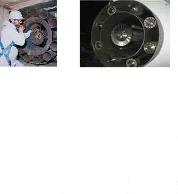
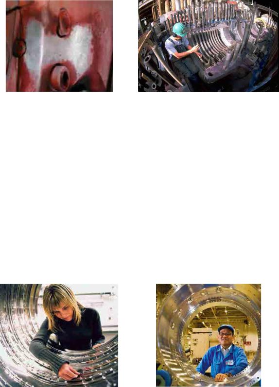
1)Confirmation of status of bearing and shaft
a.It must be confirmed sticking, damage of contact face, status of lubricant oil, bend of shaft and foreign objects etc. It must be taken appropriate measures depending on degree of defect when detecting defect at bearings.
2)Confirmation of status of casing
259
a.It must be confirmed erosion and corrosion of inside face, damage of bolts and status of gland packing etc. It must be ground down and welded erosion and corrosion portion when it is minor damage. It must be removed to manufacture factory and maintained it when it is major damage. It may be maintained them and used continuously when defects in bolts and gland packing are minor. It must be exchanged to new parts when defects in bolts and gland packing are major.
3)Confirmation of status of gear coupling
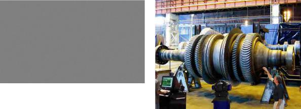
a.It must be confirmed status of contact face, crack, centering and movement of shaft etc. It must be taken appropriate measures depending on degree of defect when detecting defect at gear coupling.
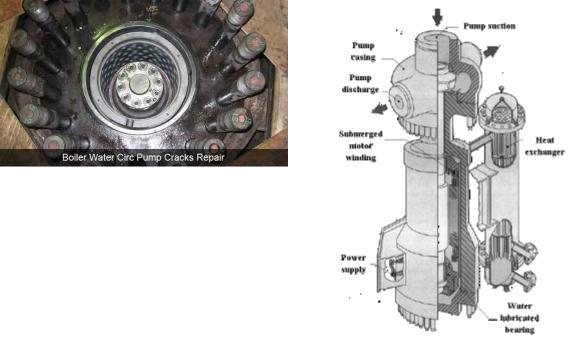
http://www.fieldsystems.com/turbine-overhauls/
Reference P-7 of Journal No.56 Aug. /2005 of TEMPES
Photo 160-14 Finished seat of BCP
Figure 160-2 Submerge wet motor type BCP
Article160-a1 Material damages and diagnosis technique of SC and USC boiler
In power industry, a lot of SC boilers and USC boilers are adopted and use condition of boiler tube is severe increasingly because steam condition of boiler is high temperature and pressure compared to conventional condition. Thus, material damages and diagnosis technique of boiler tube is explained as follows.
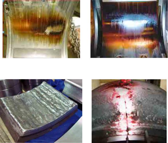
1. High temperature corrosion (Coal ash corrosion)
When low melting sulfur compound (alkali iron sulfate) is produced high temperature super-heater and re-heater, boiler tube is corroded. As the result of status of corrosion and fouling on super-heater tube made by austenitic stainless steel, abundance of Sodium (Na), Potassium (K) and Sulfur (S) is
260
higher than other ingredient and it presumes that low melting alkali iron sulfate ((NaK)3Fe(SO4)3) is produced. Corrosion by alkali iron sulfate is affected by concentration of SO2 in exhaust gas. Thus, when using high sulfur coal, it must be paid attention to high temperature corrosion. Effective countermeasure to prevent corrosion is to change material such as adoption of 25Cr steel.
Reference: P-17 of Vol.62 Jul. /2011 of Journal TEMPES
Reference: P-17 of Vol.62 Jul. /2011 of Journal TEMPES
Figure 160-a1-1 Coal ash corrosion
2. High temperature corrosion (Vanadium attack)
There is a possibility that low melting Na2O-V2O5 chemical compound is produced and corroded with accelerating speed by Vanadium and Sodium etc. in heavy oil at high temperature super-heater and re-heater of oil-fired boiler. Corrosion is produced at bending parts of piping spacer installation parts which products of combustion are attached. Mechanism of corrosion is accelerated oxidization based on oxygen supply by oxidation-reduction of Na2O-V2O5 chemical compound and destruction of oxide film by melting. In general, accelerated oxidization by Na2O-V2O5 chemical compound calls “Vanadium attack” because chemical compound is different by attached parts and fuel aspect. When there is a possibility that Vanadium attack is produced, chemical compound including mainly Calcium (Ca) and Magnesium (Mg) is attached fuel to prevent to product low melting Vanadium chemical compound.
261
Flue
gas Corroded part
Reference: P-17 of Vol.62 Jul. /2011 of Journal TEMPES
Reference: P-17 of Vol.62 Jul. /2011 of Journal TEMPES
Figure 160-a1-2 Corroded part of SH
Photo 160-a1-1 Exterior of generated
corrosion due to Vanadium attack
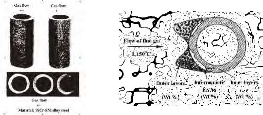
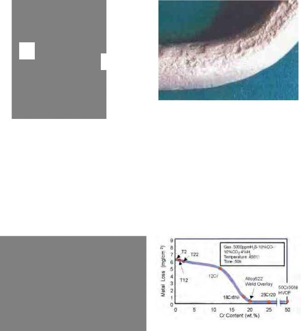
3. Sulfidation corrosion
Boiler is burned in lack of combustion air by 2 stage combustion and low NOx burner to prevent to produce NOx at combustion. In this case, there is a possibility that gas corrosion is produced by hydrogen sulfide (H2S) at water wall tube near burner. Material including more than 18% of Chromium (Cr) can prevent sulfidation corrosion. Thus, surfacing treatment by thermal spray of 50Cr50Ni and cladding by welding of Alloy 622 is conducted as countermeasure of corrosion.
Reference: P-18 of Vol.62 Jul. /2011 of Journal TEMPES
Figure 160-a1-3 Sulfide corrosion on water wall
Reference: P-18 of Vol.62 Jul. /2011 of Journal TEMPES
Figure 160-a1-4 Relation sulfide corrosion/ amount of Cr
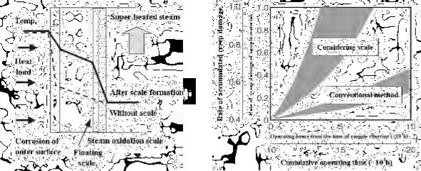
4. Steam oxidation
Steam oxidation scale is produced inside of super-heater and re-heater tube, header and piping of boiler. Trouble due to steam oxidation is blockage of tube by accumulating peeled scale and erosion of steam turbine parts by peeled scale. Steam oxidation of ferritic steel and austenitic stainless steel is explained as follows.
(1)Ferritic steel
Scale of low alloy steel or high Chromium (Cr) ferritic steel is composed of isopachous internal and external layer. External layer scale is magnetite (Fe3O4) and internal layer scale is spinel
262
type oxide including Fe and Cr. Growth behavior is indicated by following parabola law. d2 = Kp X t
Log Kp = a / T X b
d
: thickness of scale (μm), Kp : parabola speed (μm2 /h ), t
: time (h)
T : absolute temperature (K),
a & b : constant number
Growth
speed of scale depends
on Chromium volume in
material, and it is large when
temperature of material is high. When measuring thickness of scale at periodic inspection, metal temperature in use can be presumed by using above formula and remaining life assessment by creep damage analysis can be conducted.
(2)Austenitic stainless steel
In austenitic stainless steel, when thickness of internal layer scale is 50μm, external layer scale is started peeling. Thus, growth behavior of scale depends on thickness of internal layer scale. Thickness of internal layer scale is decreased in connection with increase ofChromium volume.
However, growth of scale is prevented by conducting cold working inside of low Chromium tube. Spreading of Chromium by cold working is facilitated at metal parts near internal surface of tube and protective film of Chromium oxide is produced on surface from usage early stage. Therefore, cold working is most efficient countermeasure ofsteam oxidation scale in austenitic stainless steel.
5.Scale overheat
Overheat damage due to inhibition of heat transmission by thick scale become actually recently. When scale is produced thick, metal temperature due to inhibition of heat transmission by scale is increased, corrosion is accelerated by steam oxidation of tube inside and high temperature oxidization of tube outside. Therefore, it must be assessed creep damage in consideration of theses metal temperature rise
and corrosion. There is a possibility that creep damage is accelerated due to inhibition of heat transmission by lift and lamination layer of inside steam oxidation scale in actual boiler.
263
Reference: P-19 of Vol.62 Jul. /2011 of Journal TEMPES
Reference: P-19 of Vol.62 Jul. /2011 of Journal TEMPES
Photo 160-a1-2 Cross section of scale
Figure 160-a1-5 Arrhenius plot of constant
rate of radiation between Cr-Mo steel and 9Cr
steel
6. CWT scale
SC boiler and USC boiler is once-through boiler mainly and water treatment of them changes AVT to CWT. Because CWT scale is composed of thin hematite (αFe2O3) scale less than 2μm and thin oxidization scale ((Fe, Cr) 3O4) less than 20μm, surface of scale is smooth and differential pressure rise is prevented. However, when particulate hematite (αFe2O3) scale is attached, overheat damage and circumferential crack (elephant skin) is produced. Particulate scale is micro-particle less than 3μm and is attached on oxidization scale. The results of creep damage analysis in case that particulate scale is attached are shown as follows;
Table 160-a1-1 The results of creep damage analysis
Metal temperature
Creep life
(oC)
(hours)
460 (base)
Over 100 X 104
540 (+80)
3 – 6 X 10⁴
As shown in above table, when metal temperature is increased by particulate scale, creep life is reduced severely. This trouble is confirmed at power plant which average concentration of Fe in feed water at inlet of economizer is more than 2 ppb. Therefore, it is recommended that concentration of Fe in feed water is reduced as countermeasure of this trouble.
264
Reference: P-20 of Vol.62 Jul. /2011 of Journal TEMPES
Reference: P-21 of Vol.62 Jul. /2011 of Journal TEMPES
Figure 160-a1-6 Schematic sectional view of
Figure 160-a1-7 Evaluation of creep damage
scale formation on heat transfer tube
7. Inspection procedure
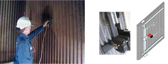
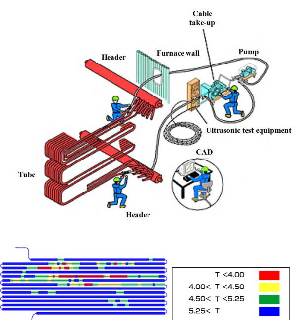
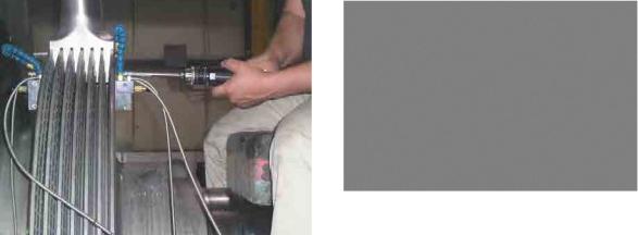
High strength high Cr steel is adopted to material of main steam piping and high temperature reheat steam piping in connection with installing SC and USC boiler. However, wall thickness of high strength high Cr steel is incrassate in connection with increasing steam temperature and pressure, steam leak at fine grain area of welding heat-affected part due to creep damage such as crack is concerned and proper damage diagnosis technique is required. Inspection procedure of damage parts is important with a view to this situation and inspection device of piping inside and inapproachable area is developed recently. Inner ultrasonic testing (UT) method and ultrasonic noise method are explained as follows;
(1)Inner ultrasonic testing method
Wall thickness of super-heater, re-heater and economizer tube is inspected by ultrasonic method. However, inspection of a lot of boiler tube is difficult because they are installed at high location and supplemental work such as cleaning of scale requires much time. Inner ultrasonic testing method is in practical use to enhance working efficiency and reliability at inspecting this boiler tube. Current this method can go through bending part of 35mm in radius smoothly and measure thickness of tube, inspection operator can confirm measuring result rapidly inputting measuring data in personal computer. Outline of inner ultrasonic testing method is shown in Figure 160-a1- 8.
265
Figure 160-a1-8 Outline of inner ultrasonic testing method (MHI)
(Unit : mm)
Figure 160-a1-9 Sample of measuring result of boiler tube
(2)Ultrasonic noise method
In creep damage, voids are produced at grain boundary, they are increased, grew, coupled and became micro-cracks, micro-cracks are coupled, grew and fractured. Inner ultrasonic testing method is useful for detecting crack and dent, but it is difficult to detect creep damage before micro-crack such as creep void. Therefore, ultrasonic noise method is developed to detect these minute creep damage. This method analyzes back scattered noise reflected by minute damage such as void when ultrasonic is passed through material inside. Measured noise value is increased based on accumulation of creep damage shown in Figure 160-a1-10, this method is utilized it’s characteristic.
266
Non-damaged material
Damaged material
Initial pulse
Back-wall reflection
Initial pulse
Back-wall reflection
Time gate
Time gate
Amplitude
Time
Time
Scattered noise
Amplitude
Void
Back-wall reflection
Frequency
Frequency
FFT: Fast Fourier Transform
Figure 160-a1-10 Fundamental principle of ultrasonic noise method
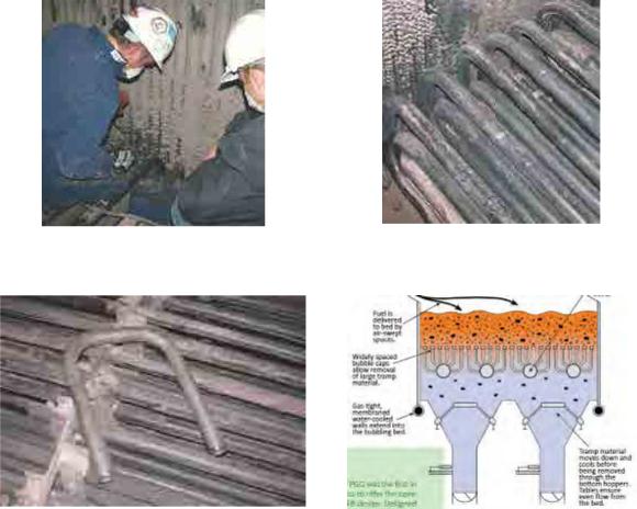
In fluidized bed boiler,fluidization gas (air etc.) is supplied to combustion chamber filling bed materials (silica sand (inert particle), limestone and ash of combustion) through under dispersion plate
and fluidized bed is produced. Combustion reactionatlow temperature (800~9 0oC) and desulfurization reaction by limestone are conducted in this fluidized bed.
Fluidized condition of particle in combustion chamber depends on diameter of particle and velocity of fluidization gas and classifies“Bubbling fluidized bed”, Circulating” fluidized bed” and ”Air transport”.
Type of fluidized bed boiler is classified by fluidized condition of particle in combustion chamber and operation pressure as follows;
-Bubbling fluidized bed boiler
-Circulating fluidized bed boiler
-Pressurized fluidized bed boiler
2.Inspection of fluidized bed boiler
Basically, structure of fluidized bed boiler is same as it of conventional boiler.Major trouble items of boiler are as follows;
-Abrasion
-Corrosion
-Fatigue
-Creep
In fluidized bed boiler, it must be confirmedparticularly following trouble and parts because boiler tube is contacted with bed materials.
268
(1)Trouble
1)Abrasion
2)Corrosion
(2)Inspection parts
1)Furnace (Evaporator)
a.Header
b.Tube
2)Super-heater
a.Header
b.Tube
3)Re-heater
a.Header
b.Tube
(3)Inspection procedure
1)Visual check
2)Detailed inspection for abrasion and corrosion of tube
3)Measurement of radial thickness
4)Inspection of welded parts of header and tube And others
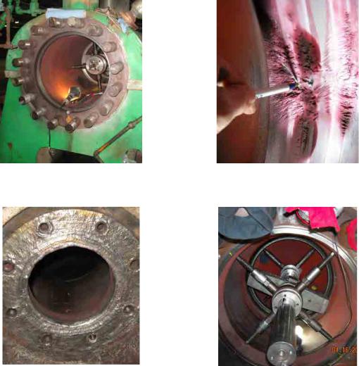
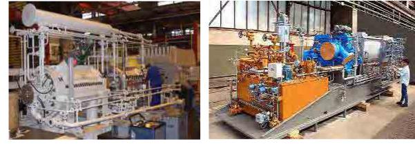
It must be conducted external inspection for damage and crack of pump body etc. It must be taken appropriate measures depending on degree of defect when detecting defect at pump. It must be open inspection depending on degree of defect if necessary.
2)Operation test
It must be conducted operation test according to following procedure and confirmed following items to detect defects of pump. It must be taken appropriate measures depending on degree of defect when detecting defect at pump.
a.Test procedure
(a)It must be confirmed following items as preparation of start up.
a)Auxiliary device and related valves are powered.
b)Oil transfer pump for BFPT is automatic position.
270
c)Oil tank gas extraction device for BFPT is operated.
d)Oil cooler for BFPT is ready for start up.
(b)BFPT is filled by feed water.
a)Deaerator level
b)BFP seal water pump is automatic position.
(c)Turning device is started up.
a)Oil pressure (high and low pressure control oil, bearing oil)
b)Outlet oil temperature of oil cooler
(d)BFPT is vacuumized.
(e)BFPT is reset position.
(f)BFPT is started up. b. Point to be checked
(a)Pump feed rate
(b)Pump outlet pressure
(c)Bearing temperature
(d)Abnormal vibration
(e)Abnormal noise etc.
3)Open inspection
It is recommended that inspection interval is regulateddepending on operation status of power plant etc. and open inspection for following items is conducted.
a.Confirmation of corrosion, erosion and crack
It must be confirmed corrosion, erosion and crack of each pump parts after disassembling. It must be ground down and welded corrosion, erosion and crack portion when it is minor damage. It must be removed to manufacture factory and maintained it when it is major damage.
b.Confirmation of foreign objects and sticking damage of rotating parts
It must be confirmed foreign objects and sticking damage of rotating parts after disassembling. It must be taken out foreign objects and taken appropriate measures depending on degree of defect when detecting defect at rotating parts.
c.Confirmation of status of deposition
It must be confirmed that ingredient and volume etc. of deposition at this pump at disassembling. It is recommended that they are analyzed chemically by specialized agency if necessary. It must be confirmed analysis results and taken appropriate measures if necessary.
d.Confirmation of gap of each pump part
It must be confirmed gap of each pump parts according to regulated gap. It must be
271
amended appropriate gap when detecting abnormal gap at each pump parts.
e.Confirmation of curvature of pump shaft
It must be confirmed curvature of pump shaft after disassembling. It must be taken appropriate measures depending on degree of defect when detecting defect at each pump parts.
It must be conducted operation test and confirmed following items to detect defects of steam turbine. It must be taken appropriate measures depending on degree of defect when detecting defect at pump. It must be referred to above 2) Operation test of (1) Feed water pump
a.Bearing temperature
b.Revolution
272
c.Abnormal vibration
d.Abnormal noise etc.
2)Open inspection
It is recommended that inspection interval is regulated depending on operation status of power plant etc. and open inspection for following items is conducted.
a.Confirmation of corrosion, erosion, crack, abrasion, deformation, dent and foreign object
It must be confirmed of corrosion, erosion, crack, abrasion, deformation, dent and foreign object of each steam turbine parts after disassembling. It must be taken appropriate measures depending on degree of defect when detecting defect at each steam turbine parts.
b.Confirmation of damage of blade and blade root etc.
It must be confirmed damage of blade and blade root etc. after disassembling. It must be taken out taken appropriate measures depending on degree of defect when detecting defect at blade and blade root etc.
c.Confirmation of damage of steam strainer and steam control valve etc.
It must be confirmed damage (abrasion and deformation etc.) of steam strainer and steam control valve etc. after disassembling. It must be taken appropriate measures depending on degree of defect when detecting defect at steam strainer and steam control valve etc.
d.Confirmation of evidence of steam and oil leakage
It must be confirmed evidence of steam and oil leakage after disassembling and cause of leakage when detecting it. It must be taken appropriate measures depending on degree of defect when detecting defect at steam turbine of feed water pump.
e.Confirmation of status of deposition
It must be confirmed that ingredient and volume etc. of deposition at steam turbine of feed water pump at disassembling. It is recommended that they are analyzed chemically by specialized agency if necessary. It must be confirmed analysis results and taken appropriate measures if necessary.
f.Confirmation of contact face of journal and thrust bearing
It must be confirmed contact face (partial contact) of journal and thrust bearing after disassembling. It must be taken appropriate measures depending on degree of defect when detecting defect at journal and thrust bearing.
2. Fun (Forced draft fan, Induced draft fan, Gas recirculation fan and Gas mixing fan)
(1)Fan
1)External inspection
It must be conducted external inspection for damage of casing etc. It must be taken appropriate measures depending on degree of defect when detecting defect at fan. It must be open inspection depending on degree of defect if necessary.
2)Operation test
It must be conducted operation test according to following procedure and confirmed following items to detect defects of fan. It must be taken appropriate measures depending on degree of defect when detecting defect at fan.
a. Test procedure
(a)It must be confirmed related dampers and gates are opened stipulated opening.
(b)It must be confirmed related equipments are operated.
a)Air heater
b)Electric precipitator
c) Lubricant and control oil pumps etc.
(c)It must be operated fans in a moment and confirmed defect of fans.
(d)It must be operated fans at no load and confirmed defect of fans.
(e)It must be operated fans at load and confirmed defect of fans.
b.Point to be checked
(a)Wind pressure
(b)Bearing temperature
(c)Abnormal vibration
(d)Abnormal noise etc.
3)Open inspection
It is recommended that inspection interval is regulated depending on operation status of power plant etc. and open inspection for following items is conducted.
a.Confirmation of damage, corrosion and abrasion of blade and casing
It must be confirmed damage, corrosion and abrasion of blade and casing. It must be taken appropriate measures depending on degree of defect when detecting defect at blade and casing.
b.Confirmation of corrosion and abrasion of vane and damper and defect of drive mechanism
It must be confirmed corrosion and abrasion of vane and damper and defect of drive
275
mechanism for damper system. It must be taken appropriate measures depending on degree of defect when detecting defect at damper system.
c.Confirmation of damage, contact face (partial contact), abrasion and bending of bearing
It must be confirmed damage, contact face (partial contact), abrasion and bending of bearing. It must be taken appropriate measures depending on degree of defect when detecting defect at bearing.
d.Confirmation of defect of oil pumps, status of lubricant oil and plugging of strainer for lubricant oil system
It must be confirmed defect of oil pumps, status of lubricant oil and plugging of strainer for lubricant oil system. It must be taken appropriate measures depending on degree of defect when detecting defect at lubricant oil system.
e.Confirmation of status of deposition
It must be confirmed that ingredient and volume etc. of deposition at fan. It is recommended that they are analyzed chemically by specialized agency if necessary. It must be confirmed analysis results and taken appropriate measures if necessary.
http://www.thielschfes.com/media/1152/Fan.pdf
http://www.thielschfes.com/media/1152/Fan.pdf
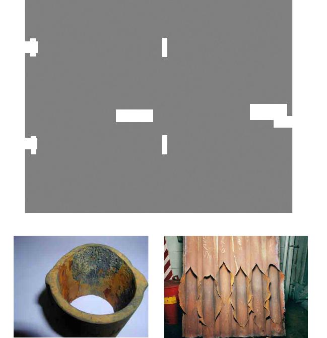
Photo 161-10 Typical cracking of fan
Photo 161-11 Typical cracking of fan
276
Table 161-1 Content of inspection for fan at the periodic inspection
Oblect
Inspection items
Inspection method
Criteria
Measure at the non-conformity
Status of dust adhesion
VT
Remove dust completely
Imbalance adjustment
Portable balancer
No crack at large bearing vibration
Field balancing
Impeller
Material and crack on weld part
VT, PT, MT
Repair, reinforcement in minor case or replacement
Existence of deformation or other damage
VT
Reinforcement or replacement
Wear situation
VT, measurement of thickness
Repair welding, replacement of liner
Corrosion situation
VT, PT, measurement of thickness
No crack, abnormal corrosion
Replacement of material, repair in case of minor
Damage on bearing
VT
Hand finish correction in minor case
Wear of shaft seal
VT
Hand finish correction in minor case
Main shaft
Bends
Dial gauge
less than 0.05mm of shaft waggle
Correction, replacement
Crack
VT, PT, MT
No crack
Replacement
Wear and corrosion
VT
Replacement in cse of large wear, corrosion
Tightness of axle nut
Correction
Touching of metal and peeling
VT, PT
Correction, replacement
Bearing
Measurement of bearing clearance
Lead wire, feeler gauge
Gap up and down, thrust
Correction, replacement
Wear and deformation of oil ring
VT
Repair welding, replacement of liner
Clearance between bearing gland and shaft
Feeler gauge
Uniform on the circumference
Correction of alignment
Clearance between impeller and casing
Dimentional inspection
No contact
Correction of installation, slignment
Wear situation
VT, measurement of thickness
No abnormal wear
Repair welding, replacement of liner
Casing
Corrosion situation
VT
No crack, abnormal corrosion
Replacement (material)
Deformation and crack
VT, PT
Reinforcement, repair welding
Status of dust adhesion
VT
Removal of dust
Shaft seal
Wear and deterioration of packing
VT
Replacement
Clearance between seal and shaft
VT
Correction and replacement
Damper
Operational status of link (hysteresis)
VT
Removal od rust, replacement of pin
Lubrication of bearing and sliding parts
Grease-gun
Correction of contact part
inlet vane
Clearance between case and vanes
VT
3. Combustion equipment (Burner)
(1)Coal firing
1)External inspection
It must be conducted external inspection for damage of coal fired combustion from inside
furnace. It must be taken appropriate measures depending on degree of defect when detecting defect at coal fired combustion.
2)Open inspection
It is recommended that inspection interval is regulated depending on operation status of power plant etc. and open inspection for following items is conducted.
a.Confirmation of damage and abrasion of inner casing, outer casing, burner nozzle and swirler
It must be confirmed damage and abrasion of inner casing, outer casing, burner nozzle and swirler of coal fired burner. It must be taken appropriate measures depending on degree of defect when detecting defect at inner casing, outer casing, burner nozzle and swirler of coal fired burner.
b.Confirmation of defect of operating portion
It must be confirmed defect of operating portion of coal fired burner. It must be taken appropriate measures depending on degree of defect when detecting defect at operating portion of coal fired burner.
277
c.Confirmation of damage of resister damper
It must be confirmed defect of resister damper of coal fired burner. It must be taken appropriate measures depending on degree of defect when detecting defect at resister damper of coal fired burner.
http://www.piburners.com/prodBW14.html
Photo 161-12 Burner repair (B&W)
http://www.piburners.com/prodBW14.html
Photo 161-13 Burner repair (B&W)
(2)Oil firing
1)External inspection
It must be conducted external inspection for damage of oil fired combustion from inside furnace. It must be taken appropriate measures depending on degree of defect when detecting defect at oil fired combustion.
2)Open inspection
It is recommended that inspection interval is regulated depending on operation status of power plant etc. and open inspection for following items is conducted.
a.Confirmation of damage and abrasion of burner tip, burner nozzle and diffuser
It must be confirmed damage and abrasion of burner tip, burner nozzle and diffuser of oil firing burner. It must be taken appropriate measures depending on degree of defect when detecting defect at burner tip, burner nozzle and diffuser of oil firing burner.
b.Confirmation of defect of operating portion
It must be confirmed defect of operating portion of oil firing burner. It must be taken appropriate measures depending on degree of defect when detecting defect at operating portion of oil firing burner.
c.Confirmation of damage of resister damper
It must be confirmed defect of resister damper of oil firing burner. It must be taken appropriate measures depending on degree of defect when detecting defect at resister damper of oil firing burner.
It must be conducted external inspection for damage of gas fired combustion from inside furnace. It must be taken appropriate measures depending on degree of defect when detecting defect at gas fired combustion.
2)Open inspection
It is recommended that inspection interval is regulated depending on operation status of power plant etc. and open inspection for following items is conducted.
a.Confirmation of damage and abrasion of burner nozzle
It must be confirmed damage and abrasion of burner nozzle of gas firing burner. It must be taken appropriate measures depending on degree of defect when detecting defect at burner nozzle of gas firing burner.
b.Confirmation of defect of operating portion
It must be confirmed defect of operating portion of gas firing burner. It must be taken appropriate measures depending on degree of defect when detecting defect at operating portion of gas firing burner.
c.Confirmation of damage of resister damper
It must be confirmed defect of resister damper of gas firing burner. It must be taken appropriate measures depending on degree of defect when detecting defect at resister damper of gas firing burner.
Table 161-2 Content of inspection for coal burner at periodic inspection
Inspection items
Inspection
Criteria
Measure at the non-conformity
method
(1) Amount of wear must be within the acceptable ra
(1) Repair by overlay welding when
overlay welding type is applying
Wear-resistantliner section
VT
(2) Repair or new replacement of wear-resistant part
must be planned in the next periodic inspection
(2) New replacement in case of wear-
according to the amount of wear measurement results
resistant cast iron type or ceramic type
Nozzle tip (wear-resistant and heat-resistant
Amount of wear must be within the acceptable range
New replacement , since most burner are
VT
using pressure-resistant and wear-
specification)
No peeling, crack and deformation
resistant cast iron or ceramic
Coal burner body
VT
No wear, cracks and fracture
Sweiler
VT
No cracks,
deformation and fixation of moving parts
Partial repair or new replacement of
Burner thought, rectifier tube
VT
No cracks and deformation
defective part according to the
Ignition burner
VT
No deformation and damage
manufacture's instruction manual
Monitoring tube (frame detector, peephole)
VT
No deformation and damage
Damper, etc.
VT
No deformation and fixation of moving parts
Burner duct
VT
No abnormal deposits of coal, ash and foreign matter
To remove sediment
Opening of burner outlet (inside the furnace)
VT
No adhesion of clinker
To remove clinker
4. Pipe attached to boiler
(1)Measurement of pipe thickness
It must be conducted measurement of pipe thickness based on measurement program developed by the Owner. It is conducted to pipe portion having potential to corrode and erode in steam and water piping. It must be taken appropriate measures depending on degree of defect when detecting defect at pipe attached to boiler.
(2)Assessment of remaining life
It must be conducted remaining life based on results of pipe thickness measurement conducted during the last periodic inspection and so on, or it must be checked and reviewed the finished assessment of remaining life.
Power plant equipments are exposed to severe environment under high pressure and temperature,
280
degradation and damage are accumulated on them and when they are not maintained, several troubles and failures are occurred. The assessment of remaining life is technology of forecasting time to be had troubles and failures based on measurement result of degradation of equipment and important technology for inspecting power plant equipment. Major assessments of remaining life have shown as below:
1)Breaking test
2)Hardness measurement method
3)Ultrasonic method
4)Electric resistance method
(3)Developing of future measurement program
It must be developed and revised measurement program of pipe thickness if necessary. It must be taken account of following items when developing and revising measurement program of pipe thickness.
1)Time of future periodic inspection
2)Period of future periodic inspection (period of boiler stopping)
3)Procedure of assessment of remaining life
4)Period of preparation of assessment of remaining life (preparation during boiler stopping)
Article 162. Steam turbine
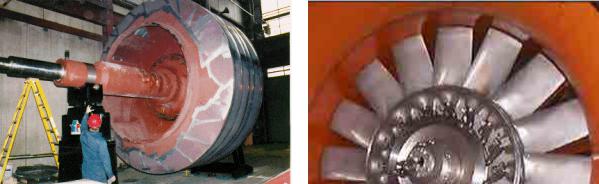
1. Casing
(1)High and middle pressure casing
Upper part of high and middle pressure casing must be removed, and inspection of them must be conducted without removing diaphragm and labyrinth packing.
1)Confirmation of erosion and corrosion
It must be confirmed erosion and corrosion of high and middle pressure casing. It must be ground down and welded erosion and corrosion portion when it is minor damage. It must be removed to manufacture factory and maintained it when it is major damage.
2)Confirmation of deformation
It must be confirmed deformation of high and middle pressure casing. It must be considered carefully measures for this damage because this damage has an effect on steam turbine operation when it is major damage. It must be removed to manufacture factory and maintained it when it is major damage. It must be ground down and welded deformation portion when it is minor damage.
3)Confirmation of contact face between rotating parts and stationary parts
It must be confirmed contact face between rotating parts and stationary parts of high and middle pressure casing. It must be welded contact portion when it is confirmed if necessary.
281
4)Confirmation of crack of each parts
It must be confirmed crack of each part of high and middle pressure casing. It must be ground down and welded crack portion when it is minor damage. It must be removed to manufacture factory and maintained it when it is major damage.
5)Confirmation of status of deposition
It must be confirmed that ingredient and volume etc. of deposition at high and middle pressure casing. It is recommended that they are analyzed chemically by specialized agency if necessary. It must be confirmed analysis results and taken appropriate measures if necessary.
6)Confirmation of evidence of steam leakage
It must be confirmed evidence of steam leakage after disassembling and cause of leakage when detecting it. It must be taken appropriate measures depending on cause of leakage when detecting defect at high and middle pressure casing.
7)Confirmation of crack and abrasion etc. of bolt and nut
It must be confirmed crack and abrasion etc. of bolt and nut of high and middle casing. It must be removed it depending on degree of defect when detecting defect at bolt and nut of high and middle pressure casing.
8)Confirmation of clearance of each part
It must be confirmed clearance of each part of high and middle pressure casing. When clearance is not appropriate, it has an effect on power generation efficiency. It must be apply regulated clearance to each part when detecting improper clearance at high and middle pressure casing.
(2)Low pressure casing
Upper part of low pressure casing must be removed and inspection of them must be conducted without removing diaphragm and labyrinth packing. It must be referred to above provisions as maintenance items for low pressure casing.
(3)PT and UT inspection
It must be conducted PT and UT inspection if necessary.
1)PT inspection
It must be conducted PT inspection for weld part of steam turbine casing, corner parts of inner and outer face of high and middle pressure inner and outer casing, and stay of low pressure outer casing. It must be ground down and welded crack portion when it is minor damage. It must be removed to manufacture factory and maintained it when it is major damage.
2)UT inspection
It must be conducted PT inspection for weld part of steam turbine casing and thickness inspection of balance piping etc. It must be ground down and welded crack portion when it is minor damage. It must be removed to manufacture factory and maintained it when it is major damage.
282
3)Measurement of strain of horizontal coupling face
It must be conducted measurement of strain of horizontal coupling face of steam turbine casing. When there is strain at horizontal coupling face, it has an effect on power generation efficiency. It must be taken appropriate measures depending on degree of defect when detecting defect at horizontal coupling face of steam turbine casing.
(4)Detailed inspection
It is recommended that inspection interval is regulated and MT inspection is conducted for high stress portion of steam turbine casing.
(sample of inspection interval : every 8 years or 60,000 80,000 hrs)
Within the opened range of casing, it must be inspected following items by quietly rotating rotor without removing it.
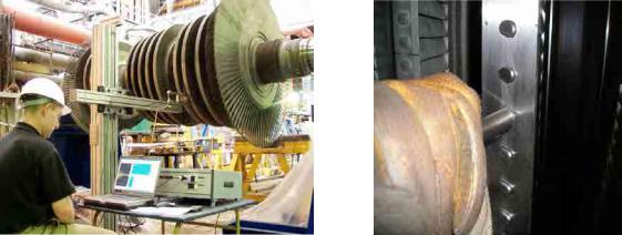
1)Confirmation of rotor position, alignment and fluctuation
It must be confirmed rotor position, alignment and fluctuation of steam turbine rotor. It must
283
be taken appropriate measures depending on degree of defect when detecting defect at steam turbine rotor.
2)Confirmation of corrosion and erosion
It must be confirmed erosion and corrosion of steam turbine rotor. It must be ground down erosion and corrosion portion when it is minor damage. It must be removed to manufacture factory and maintained it when it is major damage.
3)Confirmation of status of deposition
It must be confirmed that ingredient and volume etc. of deposition at steam turbine rotor. It is recommended that they are analyzed chemically by specialized agency if necessary. It must be confirmed analysis results and taken appropriate measures if necessary.
4)Confirmation of contact between rotor and stationary part
It must be confirmed contact between steam turbine rotor and stationary part. It must be taken appropriate measures depending on degree of defect when detecting defect at contact between steam turbine rotor and stationary part.
and solutions” by Jonas, Inc.: The 37th turbo-machinery symposium
alignment/oasis-alignment3.html
2008
Figure 162-3 Construction of welded type
Photo 162-4 Laser tracker inspection of rotor
rotor
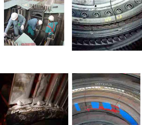
(2)Turbine disk
Within the opened range of casing, it must be inspected following items by quietly rotating rotor without removing it.
1)Confirmation of corrosion and erosion
It must be confirmed erosion and corrosion of turbine disk of steam turbine. It must be ground down and welded erosion and corrosion portion when it is minor damage. It must be removed to manufacture factory and maintained it when it is major damage.
2)Confirmation of clearance of blade portion and gap of each part
It must be confirmed clearance of blade portion and gap of each part of turbine disk of steam turbine. When clearance and gap is not appropriate, it has an effect on power generation efficiency. It must be apply regulated clearance and gap when detecting improper clearance and gap at turbine disk of steam turbine.
3)Confirmation of contact between turbine disk and stationary part
It must be confirmed contact between turbine disk and stationary part of steam turbine. It must be taken appropriate measures depending on degree of defect when detecting defect at contact between turbine disk and stationary part of steam turbine.
4)Confirmation of status of deposition
It must be confirmed that ingredient and volume etc. of deposition at turbine disk of steam turbine. It is recommended that they are analyzed chemically by specialized agency if necessary. It must be confirmed analysis results and taken appropriate measures if necessary.
Reference: P-9 of “Steam turbine corrosion and deposits problems
Reference: P-9 of “Steam turbine corrosion and deposits problems
and solutions” by Jonas, Inc.: The 37th turbo-machinery symposium
and solutions” by Jonas, Inc.: The 37th turbo-machinery symposium
2008
2008
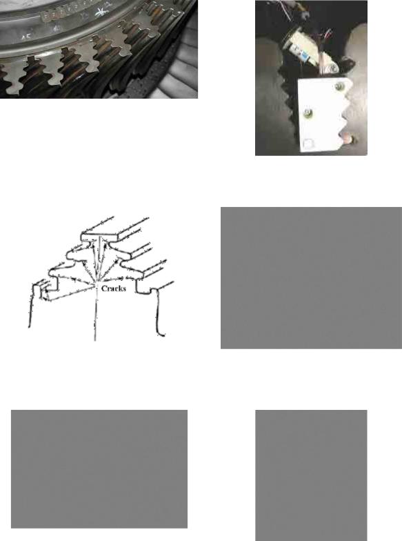
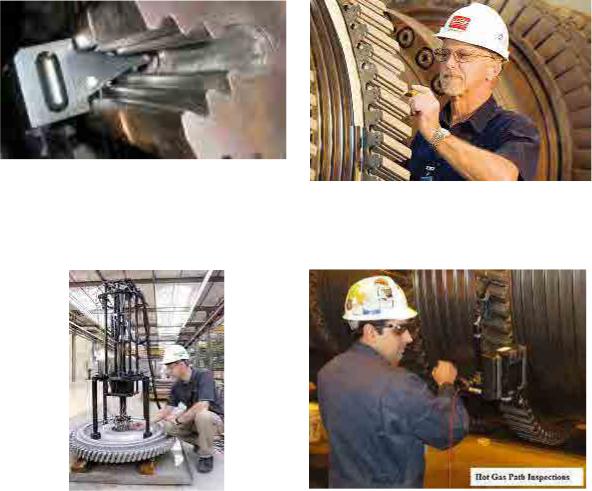
Figure 162-4 Crack on notch entry dovetail
Figure 162-5 Crack on axial entry fir tree
Reference: P-15 of “Steam turbine corrosion and deposits problems
Reference: P-15 of “Steam turbine corrosion and deposits problems
and solutions” by Jonas, Inc.: The 37th turbo-machinery symposium
and solutions” by Jonas, Inc.: The 37th turbo-machinery symposium
2008
2008
Photo 162-7 Crack on turbine disc
(3)Rotating blade and dovetail
Within the opened range of casing, it must be inspected following items by quietly rotating rotor
286
without removing it.
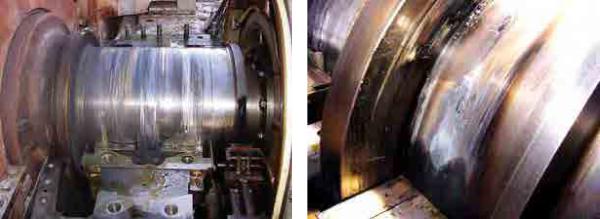
1)Confirmation of corrosion and erosion
It must be confirmed erosion and corrosion of rotating blade and dovetail of steam turbine. It must be ground down erosion and corrosion portion when it is minor damage. It must be removed to manufacture factory and maintained it when it is major damage.
2)Confirmation of clearance related rotating blade
It must be confirmed clearance between rotating blade and stationary blade or tip clearance of steam turbine. When clearance is not appropriate, it has an effect on power generation efficiency. It must be apply regulated clearance when detecting improper clearance at rotating blade of steam turbine.
3)Confirmation of contact between rotating blade and stationary part
It must be confirmed contact between rotating blade and stationary part of steam turbine. It must be taken appropriate measures depending on degree of defect when detecting defect at contact between steam turbine rotating blade and stationary part of steam turbine. It must be removed to manufacture factory and maintained it when it is major damage.
4)Confirmation of status of deposition
It must be confirmed that ingredient and volume etc. of deposition at rotating blade and dovetail of steam turbine. It is recommended that they are analyzed chemically by specialized agency if necessary. It must be confirmed analysis results and taken appropriate measures if necessary.
Reference: P-28 of “90MW GE steam turbine project”: SULZER
Reference: P-10 of “Steam turbine corrosion and deposits problems
and solutions” by Jonas, Inc.: The 37th turbo-machinery symposium
2008
Photo 162-8 Re-blading of LP rotor
Photo 162-9 Crack on dovetail of blade
(4)Shroud ring and lacing wire
Within the opened range of casing, it must be inspected following items by quietly rotating rotor without removing it.
287
1)Confirmation of erosion and loose of shroud
It must be confirmed erosion and loose of shroud of steam turbine. It must be taken appropriate measures depending on degree of defect when detecting defect at shroud of steam turbine
2)Confirmation of damage of lacing wire
It must be confirmed damage (breakage etc.) of lacing wire. It must be taken appropriate measures depending on degree of defect when detecting defect at lacing wire of steam turbine
Reference: P-289of “90MW GE steam turbine project”: SULZER
Photo 162-10 UT of blade attachment
Photo 162-11 Shroud installation
(Siemens)
(5)PT and UT inspection
1)PT inspection
It must be conducted PT inspection for curvature portion of rotor outer surface, shroud ring and weld portion of rotating blade stub etc. It must be ground down damaged portion when it is minor damage. It must be removed to manufacture factory and maintained it when it is major damage.
2)UT inspection
It must be conducted UT inspection for blade groove of rotor etc. of steam turbine. It must be ground down damaged portion when it is minor damage. It must be removed to manufacture factory and maintained it when it is major damage.
(6)Detailed inspection
It is recommended that inspection interval is regulated and material inspection and measurement of hardness are conducted for high stress portion.
(sample of inspection interval : every 8 years or 60,000 80,000 hrs)
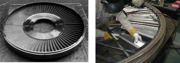
3.Diaphragm, nozzle, stationary blade
(1)Diaphragm (stationary blade)
It must be conducted inspection with diaphragm fixed in steam turbine casing.
288
1)Confirmation of corrosion and erosion
It must be confirmed corrosion and erosion of diaphragm of steam turbine. It must be ground down erosion and corrosion portion when it is minor damage. It must be removed to manufacture factory and maintained it when it is major damage.
2)Confirmation of crack
It must be confirmed crack of diaphragm of steam turbine. It must be ground down erosion and corrosion portion when it is minor damage. It must be removed to manufacture factory and maintained it when it is major damage.
3)Confirmation of status of deposition
It must be confirmed that ingredient and volume etc. of deposition at diaphragm of steam turbine. It is recommended that they are analyzed chemically by specialized agency if necessary. It must be confirmed analysis results and taken appropriate measures if necessary.
4)Confirmation of status of horizontal coupling face
It must be confirmed status (steam leakage) of horizontal coupling face of diaphragm of steam turbine and cause of leakage when detecting it. It must be taken appropriate measures depending on cause of leakage when detecting defect at diaphragm of steam turbine.
Reference: P-8 of “90MW GE steam turbine project”: SULZER
Reference: P-8 of “90MW GE steam turbine project”: SULZER
Photo 162-12 Completed diaphragm
Photo 162-13 Replacement of vanes
(2)Nozzle (stationary blade)
It must be conducted inspection of first stage of nozzle at the upper part of high and middle pressure. It must be referred to above provisions as maintenance items for nozzle of steam turbine.
It must be PT inspection and measurement of gap for diaphragm and nozzle of steam turbine if necessary.
1)PT inspection
It must be conducted PT inspection for diaphragm and nozzle of steam turbine. It must be ground down damaged portion when it is minor damage. It must be removed to manufacture factory and maintained it when it is major damage.
2)Measurement of gap
It must be conducted measurement of gap for diaphragm and nozzle of steam turbine. When gap is not appropriate, it has an effect on power generation efficiency. It must be apply regulated gap to each parts when detecting improper gap at diaphragm and nozzle of steam turbine.
290
4. Bearing
(1)External inspection
It must be conducted external inspection for bearing of steam turbine.
1)Confirmation of oil gap
It must be confirmed oil gap for bearing of steam turbine. When oil gap is not appropriate, it has an effect on operating steam turbine. It must be apply regulated gap when detecting improper gap at bearing of steam turbine.
2)Confirmation of contact to turbine rotor
It must be confirmed contact to turbine rotor and contact width etc. for bearing of steam turbine. When they are not appropriate, bearing and rotor for steam turbine are damaged. It must be confirmed cause of defect for bearing of steam turbine and taken measures depending on this cause.
3)Confirmation of spherical gap
It must be confirmed spherical gap for bearing of steam turbine. When spherical gap is not appropriate, it has an effect on operating steam turbine. It must be apply regulated gap when detecting improper gap at bearing of steam turbine.
4)Confirmation of thrust gap
It must be confirmed thrust gap for bearing of steam turbine. When thrust gap is not appropriate, it has an effect on operating steam turbine. It must be apply regulated gap when detecting improper gap at bearing of steam turbine.
5)Confirmation of contact to thrust bearing pad
It must be confirmed contact to thrust bearing pad for bearing of steam turbine. When they are not appropriate, bearing and rotor for steam turbine are damaged. It must be confirmed cause of defect for bearing of steam turbine and taken measures depending on this cause.
5. Main valve (Main stop valve, reheat stop valve and governor valve)
(1)Open inspection
It must be disassembled each individual main valve and conducted inspection for strainer, valve body, valve seat, etc of them.
1)Confirmation of crack, erosion and abrasion
It must be confirmed crack, erosion and abrasion for valve stem, casing, weld part, bolt and nut of main valve. It must be ground down erosion and crack portion when it is minor damage. It must be removed to manufacture factory and maintained it when it is major damage. It must be taken appropriate measures depending on degree of defect when detecting defect at main valve of steam turbine.
2)Confirmation of contact to valve, valve seat and valve stem
It must be confirmed contact to valve, valve seat and valve stem of main valve. When they are not appropriate, steam leakage is occurred. It must be confirmed cause of steam leakage of main valve and taken measures depending on this cause.
3)Confirmation of status of deposition
It must be confirmed that ingredient and volume etc. of deposition at main valve of steam turbine. It is recommended that they are analyzed chemically by specialized agency if necessary. It must be confirmed analysis results and taken appropriate measures if necessary.
4)Confirmation of erosion and abrasion for gland packing
It must be confirmed erosion and abrasion for gland packing of main valve. It must be exchanged to new gland packing if necessary. It must be taken appropriate measures depending on degree of defect when detecting defect at gland packing of main valve.
(2)PT inspection
It must be conducted PT inspection for valve disc, valve stem, valve seat and welded part etc. of main valve if necessary. It must be taken appropriate measures depending on degree of defect when detecting defect at main valve of steam turbine.
It must be conducted external inspection for crack, corrosion and abrasion etc. of emergency governor and tripping device, etc. It must be taken appropriate measures depending on degree of defect when detecting defect at emergency governor and tripping device, etc.
(2)Open inspection
It is recommended that inspection interval is regulated and open inspection is conducted
1)Emergency stop device
a.Confirmation of status of trip lever pin and lock bolt
It must be confirmed status of trip lever pin and lock bolt of emergency stop device. It must be taken appropriate measures depending on degree of defect when detecting defect at trip lever pin and lock bolt of emergency stop device.
b.Confirmation of deformation of spring
It must be confirmed deformation of spring of emergency stop device. It must be exchanged to new spring when the deformation is major. It must be taken appropriate
293
measures depending on degree of defect when detecting defect at spring of emergency stop device.
c.Confirmation of damage and corrosion of sliding surface of spindle
It must be confirmed damage and corrosion of sliding surface of spindle of emergency stop device. It must be taken appropriate measures depending on degree of defect when detecting defect at sliding surface of spindle of emergency stop device.
2)Governor
a.Confirmation of sludge and foreign object of strainer and oil orifice etc.
It must be confirmed sludge and foreign object of strainer and oil orifice etc. of governor.
It must be removed sludge and foreign object when detecting them at strainer and oil orifice etc. of governor. It must be confirmed cause of foreign object if necessary.
Confirmation of damage, abrasion and deformation of bearing, lever, spindle, spring and pin
It must be confirmed damage, abrasion and deformation of bearing, lever, spindle, spring and pin of governor. It must be exchanged to new parts when damage, abrasion and deformation are major. It must be taken appropriate measures depending on degree
of defect when detecting defect at bearing, lever, spindle, spring and pin of governor.
b.Confirmation of crack and deformation of diaphragm
It must be confirmed crack and deformation diaphragmof of governor. It must be exchanged to new diaphragm when crack and deformation are major. It must be taken appropriate measures depending on degree of defect when detecting defect at diaphragm of governor.
7.Condenser
(1)Visual inspection
It must be opened condenser water box and conducted visual inspection of inside and condenser tubes.
1)Condenser water box and tube plate
a.Confirmation of corrosion
It must be confirmed corrosion of tube platepartitionof wall. It must be taken appropriate measures depending on degree of defect when detecting defect at tube plate of partition wall.
b.Confirmation of status of deposition
It must be confirmed that deposition atondenserc water boxand tube plate. It is recommended that they are analyzed chemically by specialized agency if necessary. It must be confirmed analysis results and taken appropriate measures if necessary.
c.Confirmation of exfoliation and damage of lining
It must be confirmedexfoliation and damage of lining of condenser water box. It must
be exchanged to new lining if necessary. It must be taken appropriate measures depending on degree of defect when detecting defect at lining of condenser water box.
294
2)Condenser tube
a.Confirmation of corrosion and erosion
It must be confirmed corrosion and erosion of inner face of condenser tube. It must be exchanged new condenser tube or attached stoppage plug to damaged condenser tube when corrosion and erosion of inner face is major. It must be taken appropriate measures depending on degree of defect when detecting defect at condenser tube.
b.Confirmation of status of deposition
It must be confirmed that deposition at inner face of ondenserc tube. It is recommended
that they areanalyzed chemically by specialized agency if necessary. It must be confirmed analysis results and taken appropriate measures if necessary.
Article162-a1 Remaining life diagnosis technique of steam turbine
1. Remaining life diagnosis technique
Remaining life diagnosis is intended to predict the remaining lifeafter evaluating the life at the periodic inspection, and carried out for the main equipment of aged thermal power plant operation time exceeds 100,000 hours. The methods of diagnosis are non-destructive inspection, analysis and destructive inspection. Because in many parts it can be diagnosed in a relatively short periodand it
can also do
regular
monitoring, it has
been promoted
to
principal
diagnosis by -nondestructive
inspection. Table 162-a1-1 shows an
example
of remaining
lifediagnosis
technique
by non-
destructive inspection.
Table 162-a1-1 The remaining life diagnosis technique by non-destructive inspection
Method
Damage pattern
Creep
Fatigue
Embrittlement
Remarks
Electrical resistance method
X
Hardness measurement method
X
Organization observation method
X
Replica
Micro crack measurement method
X
Replica
Etch method
X
Replica
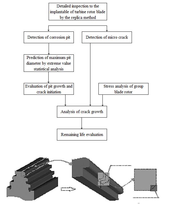
2. Life evaluation method of low-pressure turbine rotor
Life evaluation of low-pressure turbine rotoris
important to analyze the crack initiation and
progression from corrosion pits. Therefore, as the first phase of the maintenance management of the
low-pressure
turbine
rotor, to understand the
damage
state of
the
corresponding,
at the time of
inspection of sampling rotor blades, the application of the replica method to the implantable of turbine rotor blade is recommended together with the chemical analysis of the precipitates. Figure 162a1- -1 shows the flow of this remaining life evaluation.In addition, figure 162-a1-2 shows the example of the application of the replica method in blade groove of rotor wheel.
296
Figure 162-a1-1 Remaining life evaluation
Blade groove
Replica firm
Blade groove of wheel
The first stage hook
Figure 162-a1-2 The application of the replica method in blade groove of rotor wheel
Article 163. Steam turbine auxiliary equipment
1. Tube attached to steam turbine
It must be conducted the following management for tube thickness in consideration of status of each tube if necessary.
297
(1)Measurement of pipe thickness
It must be conducted measurement of pipe thickness based on measurement program developed by the Owner. It is conducted to pipe portion suspected corrosion wastage in steam piping. It must be taken appropriate measures depending on degree of defect when detecting defect at pipe attached to steam turbine.
(2)Assessment of remaining life
It must be conducted remaining life based on results of pipe thickness measurement conducted during the last periodic inspection and so on, or it must be checked and reviewed the finished assessment of remaining life.
Power plant equipments are exposed to severe environment under high pressure and temperature, degradation and damage are accumulated on them and when they are not maintained, several troubles and failures are occurred. The assessment of remaining life is technology of forecasting time to be had troubles and failures based on measurement result of degradation of equipment and important technology for inspecting power plant equipment. Major assessments of remaining life have shown as below:
1)Breaking test
2)Hardness measurement method
3)Ultrasonic method
4)Electric resistance method
(3)Developing of future measurement program
It must be developed and revised measurement program of pipe thickness if necessary. It must be taken account of following items when developing and revising measurement program of pipe thickness.
1)Time of future periodic inspection
2)Period of future periodic inspection (period of boiler stopping)
3)Procedure of assessment of remaining life
4)Period of preparation of assessment of remaining life (preparation during boiler stopping)
Article 164. Gas turbine (internal combustion)
1. Compressed combustion gas supply equipment and its auxiliary equipment
The auxiliary equipment of compressed combustion gas supply equipment is the equipment that supplies compressed gas for combustion to gas turbine together with gas compressor proper.
It must be regulated overhaul and inspection interval based on manufacture manual and actual operation status etc. and conducted overhaul and inspection of gas compressor.
298
(1)Gas compressor
1)Overhaul and inspection
It must be conducted overhaul and inspection of gas compressor on following parts and defects. These parts may be maintained and used continuously when defects in gas compressor are minor. It must be exchanged to new parts when defects in gas compressor are major. If inspection is periodically conducted by means of time management and so on according to the equipment properties, inspection must be conducted as long as it may be necessary.
a.Reciprocal engine type
(a)Frame
a)Clearance measurement of bearing and crosshead
b)Crack and deformation of connecting rod
c)Lubricant oil volume
(b)Cylinder
a)Fluctuation of cylinder
b)Abrasion and damage of piston ring, packing and seal ring etc.
c)Clearance measurement of piston outer shape and piston end
(c)Lubricant oil system
a)Gear and bearing of oil pump
b)Erosion, leakage and crack of oil cooler tube
(d)Airtight test by using nitrogen (After assembling)
(e)Leak test by gas detector (After assembling)
b.Turbo engine type
(a)Gas compressor body
a)Damage and abrasion of rotor, bearing, casing and impeller etc.
b)Alignment
(b)Lubricant oil system
a)Gear and bearing of oil pump
b)Erosion, leakage and crack of oil cooler tube
(c)Airtight test by using nitrogen (After assembling)
It must be conducted appearance check of gas receiver, gas cooler and oil separator on following part. These parts may be maintained and used continuously when defects in gas receiver, gas cooler and oil separator are minor. It must be exchanged to new parts when defects in gas receiver, gas cooler and oil separator are major.
a.Status of rust, deformation and damage at each part of gas receiver, gas cooler and oil separator body
(a)External surface
(b)Contact point with auxiliary devices
(c)Painting etc.
b.Status of crack and damage at foundation of gas receiver, gas cooler and oil separator
c.Status of deformation and fracture of manhole, water spray bar, atmospheric escape pipe etc.
d.Status of peeling and fracture of sealing agent under gas receiver, gas cooler and oil separator
It must be conducted appearance check of safety valve on following defects. These parts may be maintained and used continuously when defects in safety valve are minor. It must be exchanged to new parts when defects in safety valve are major.
a.Corrosion and erosion of safety valve body
b.Abrasion of safety valve body
c. Damage of safety valve body etc.
2)Overhaul and inspection
It must be conducted overhaul and inspection of safety valve on following parts and defects. These parts may be maintained and used continuously when defects in safety valve are minor. It must be exchanged to new parts when defects in safety valve are major.
a.Abrasion of valve body, valve seat, valve stem, and seal
b.Crack, foreign object and corrosion of valve body and seat
c.Interference and free length of spring
d.Position of adjust ring
e. Crack, deformation, curvature and contact on edge of stem etc.
(4)Piping
It must be conducted appearance check of piping on following defects. These parts may be maintained and used continuously when defects in piping are minor. It must be exchanged to new parts when defects in piping are major.
1)Corrosion of piping
2)Deformation of piping
3)Damage of piping etc.
301
2. Casing
It must be regulated overhaul and inspection interval based on manufacture manual and actual operation status etc. and conducted overhaul and inspection of casing.
(1)Horizontally split gas turbine
1)Overhaul and inspection
It must be conducted overhaul and inspection of casing on following parts and defects by removing upper part of casing. These parts may be maintained and used continuously when defects in casing are minor. It must be removed to manufacture factory and maintained it or exchanged to new parts when defects in casing are major.
a.Crack and erosion of inner casing
b.Leakage of oil, compressed air and combustion gas from casing
c.Sliding contact with rotor
d.Fouling and foreign object in casing
e.Rust on outer casing etc.
2)PT inspection and clearance gap measurement
It must be conducted PT inspection and clearance gap measurement on following parts if necessary. As the results of PT inspection, these parts may be maintained and used continuously when defects in casing are minor. It must be removed to manufacture factory and maintained it or exchanged to new parts when defects in casing are major. In case that clearance gap is not met with acceptable value, it must be applied regulated gap to each part.
a.Inner face of casing and major bolts at PT inspection
b.Clearance gap between rotating blade tip and casing (tip clearance)
http://www.locknstitch.jp/lns/power.html
http://www.locknstitch.jp/lns/power.html
Photo 164-4 Repair of GT outlet casing
302
http://www.locknstitch.jp/lns/power.html
http://turbinesint.com/steam-gas-turbine/
Photo 164-5 Repair of GT outlet casing
Photo 164-6 Overhaul of GT
(2) Cylinder casing gas turbine
It must be conducted overhaul and inspection of compressor part, combustion chamber part and turbine part on following parts and defects. These parts may be maintained and used continuously when defects in them are minor. It must be removed to manufacture factory and maintained it or exchanged to new parts when defects in them are major.
1)Crack and erosion of inner compressor part, combustion chamber part and turbine part
2)Leakage of oil, compressed air and combustion gas from compressor part, combustion chamber part and turbine part
3)Sliding contact with rotor
4)Fouling and foreign object in combustion gas from compressor part, combustion chamber part and turbine part
5)Rust on outer combustion gas from compressor part, combustion chamber part and turbine part etc.
It must be regulated overhaul and inspection interval based on manufacture manual and actual
303
operation status etc. and conducted overhaul and inspection of rotor, turbine disk and rotating blade.
In general, the integration method to bind discs which is planted blades by bolts is adopted in stead of forging a single rotor for gas turbine as shown in Figure 164-1.
(1)Horizontally split gas turbine
It must be conducted overhaul and inspection of rotor, turbine disk, rotating blade on following parts and defects by quietly rotating rotor without removing it. It must be conducted PT inspection if necessary. These parts may be maintained and used continuously when defects in them are minor. It must be removed to manufacture factory and maintained it or exchanged to new parts when defects in them are major.
1)Rotor
a.Crack, erosion and corrosion
b.Contact with diaphragm and labyrinth seal
c.Sliding contact on journal part
d.Fouling etc.
Figure 164-1 Typical cross section of gas turbine (Siemens)
The typical deterioration and damage to the surface on the blades in the view point of maintenance is the metal reduction due to high temperature oxidation, though the factor of replacement life of blades in the view point of design is the creep damage, since they are used for a long period of time at high temperature and centrifugal force condition.
In particular, the blade tip portion and the front edge portion of 1st stage are remarkable as shown in Photo 164-14. In addition, it is a problem of thermal fatigue cracks occur around the blade tip or cooling vents.
It cannot be seen particular deterioration and damage on both GT systems of GE type and MHI type other than the minor deterioration of coating except the 1st stage. Inspection method at the time of inspection is visual inspection (hereinafter, VT), fluorescent inspection (hereinafter, FPT) and a dimensional inspection for both GE type and MHI type. The necessity of repair is determined based on the existence of deterioration and damage and criterion for repair. The main repair method is the repair welding for thickness reduction part due to oxidation and blending repair of crack part.
It must be conducted overhaul and inspection of rotor, turbine disk, rotating blade and so on of compressor and turbine part on following parts and defects. It must be conducted PT inspection if necessary. These parts may be maintained and used continuously when defects in them are minor. It must be removed to manufacture factory and maintained it or exchanged to new parts when defects in them are major.
1)Rotor
a.Crack, erosion and corrosion
b.Contact with diaphragm and labyrinth seal
c.Sliding contact on journal part
d.Fouling etc.
2)Turbine disk
a.Crack, erosion and corrosion
b.Contact with diaphragm and labyrinth seal
c.PT inspection
d.Fouling etc.
3)Rotating blade and blade dovetail
a.Crack, erosion and corrosion
b.Damage due to foreign object
c.PT inspection
d.Blockage and damage of cooling air hole
e.Peeling of thermal barrier coating
f.Fouling etc.
4. Diaphragm, nozzle, stationary blade
It must be regulated overhaul and inspection interval based on manufacture manual and actual operation status etc. and conducted overhaul and inspection of diaphragm, nozzle and stationary blade.
(1)Horizontally split gas turbine
It must be conducted overhaul and inspection of diaphragm, nozzle, and stationary blade by removing nozzle only at upper part on following parts and defects. It must be conducted PT inspection if necessary. These parts may be maintained and used continuously when defects in them are minor. It must be removed to manufacture factory and maintained it or exchanged to new parts when defects in them are major.
307
1)Diaphragm
a.Deformation
b.Inspection and cleaning of horizontal coupling face and insert part at casing
The morphology of typical deterioration and damage of stationary vane is the thermal fatigue crack due to thermal stress during-start-up, and occur on the blade and sidewall. In addition, it can be recognized local oxidation and creep deformation of sidewall (fall).
It can be observed a slight detachment of coating due to the very severe condition, although thermal barrier coating (TBC) has been given on the 1st stage stationary banes of GT class 1,300oC and 1,500 oC. Photo 164-17 is the 1st stage stationary blades of GT of MHI (class 1,500 oC) which were used approximately 5,000hours. The slight wear (black section) can be seen on the TBC of blade surface.
The deterioration and damage after the 2nd stage of stationary vanes is slight, though it is observed some degree of thermal fatigue crack. The inspection method is the VT, PT, dimension inspection and repair welding on crack part.
308
Reference: P-5 of No. 61 Journal Dec. /2010: TEMPES
Photo 164-17 1st stage blade MHI type GT
Photo 164-18 Stationary blade of GT
(1,500oC class)
(2)Cylinder casing gas turbine
It must be conducted overhaul and inspection of diaphragm, nozzle, stationary blade and so on of compressor part and turbine part on following parts and defects. It must be conducted PT inspection if necessary. These parts may be maintained and used continuously when defects in them are minor. It must be removed to manufacture factory and maintained it or exchanged to new parts when defects in them are major.
1)Diaphragm
a.Deformation
b.Inspection and cleaning of horizontal coupling face and insert part at casing
c.Blockage of cooling air hole
d.Inspection and cleaning of support and pin etc.
2)Stationary blade
a.Crack, erosion and corrosion
b.Damage due to foreign object
c.PT inspection
d.Blockage and damage of cooling air hole
e.Peeling of thermal barrier coating
f.Fouling etc.
5. Bearing
It must be regulated overhaul and inspection interval based on manufacture manual and actual operation status etc. and conducted overhaul and inspection of bearing.
(1)Horizontally split gas turbine
It must be conducted external inspection of bearing and conducted overhauled and inspection it on following parts and defects when taking out rotor as needed. These parts may be maintained and
309
used continuously when defects in bearing are minor. It must be removed to manufacture factory and maintained it or exchanged to new parts when defects in bearing are major.
Bearing must be disassembled and inspection must be conducted.
It must be conducted overhauled and inspection of bearing on following parts and defects when taking out rotor as needed. These parts may be maintained and used continuously when defects in bearing are minor. It must be removed to manufacture factory and maintained it or exchanged to new parts when defects in bearing are major.
310
1)Oil gap
2)Contact to turbine rotor
3)Spherical gap
4)Thrust gap
5) Contact to thrust bearing pad etc.
6. Emergency governor
(1)Horizontally split gas turbine and Cylinder casing gas turbine
1)External inspection
It must be conducted external inspection for crack, corrosion and abrasion etc. of emergency governor and tripping device etc. It must be taken appropriate measures depending on degree of defect when detecting defect at them.
2)Open inspection
It is recommended that inspection interval is regulated and open inspection is conducted a. Emergency stop device
(a) Confirmation of status of trip lever pin and lock bolt
It must be confirmed status of trip lever pin and lock bolt of emergency stop device. It must be taken appropriate measures depending on degree of defect when detecting defect at rip lever pin and lock bolt of emergency stop device.
(b) Confirmation of deformation of spring
It must be confirmed deformation of spring of emergency stop device. It must be exchanged to new spring when the deformation is major. It must be taken appropriate measures depending on degree of defect when detecting defect at spring
of emergency stop device.
(c) Confirmation of damage and corrosion of sliding surface of spindle
It must eb confirmed damage and corrosion of
sliding surface of spindle of
emergency stop device. It must be taken appropriate measures depending on degree
of defect when detecting defect at sliding surface
of spindle of emergency stop
device.
b.Governor
(a)Confirmation of sludge and foreign object of strainer and oil orifice etc.
It must be confirmed sludge andforeign object of strainer and oil orifice etc. of governor. It must be removed sludge and foreign object when detecting them at strainer and oil orifice etc. of governor. It must be confirmed cause of foreign object
if necessary.
(b)Confirmation of damage, abrasion and deformation of bearing, lever, spindle, spring and pin
311
It must be confirmed damage, abrasion and deformation of bearing, lever, spindle,
spring and pin of governor. It
must
be exchanged to new parts when damage,
abrasion
and
deformation are
major. It must be
taken appropriate
measures
depending
on
degree of defect
when
detecting defect
at bearing, lever,
spindle,
spring and pin of governor.
(c) Confirmation of crack and deformation of diaphragm
It must be confirmed crack and deformation ofdiaphragm of governor. It must be exchanged to new diaphragmwhen crack and deformation are major. It must be taken appropriate measures depending on degree of defect when detecting defect at diaphragm of governor.
7. Reduction gear
It must be regulated overhaul and inspection interval based on manufacture manual and actual operation status etc. and conducted overhaul and inspection of reduction gear.
(1)Cylinder casing gas turbine
1)Open or disassembled inspection
It must be overhauled and confirmed reduction gear on following parts and defects. These parts may be maintained and used continuously when defects in reduction gear are minor. It must be exchanged to new parts when defects in reduction gear are major.
operation status etc. and conducted overhaul and inspection of following equipments.
(1)Turbine and blades, heat exchangers, valves, dampers, accessories
1)Turbine and blades
It must be referred to paragraph 3 and 4 of Article 164 in this Guideline.
2)Heat exchangers
It must be overhauled and confirmed heat exchanger on following parts and defects. These parts may be maintained and used continuously when defects in heat exchanger are minor. It must be exchanged to new parts when defects in heat exchanger are major.
a.Erosion of heat exchanger tube
b.Deformation of heat exchanger tube
c. Leakage of heat exchanger tube etc.
The degradation of the hightemperature parts progresses whilesuperimposed the timedependent degradation such as creep and number dependent degradation such as–cyclelow fatigue, etc. Therefore, the management by means of“equivalent operation hours” that is used the law of liner damage is applied as the guideline for the operation of high temperature parts.
This is the method to evaluate by means of converting the number dependent degradation to the time dependent degradation by using the coefficient.
The evaluation formula for typical equivalent operation is shown as follows. Each factor has been specified for each high temperature parts and the lifetime consumption is different for each component in the same operating history.
By this, it becomes possible
to calculate the lifeconsumption of high temperature parts
by a
simple formula through the
actual operation hours, fuel type,and number of start-up,
I: Percent water/steam injection performance to inlet air flow
M&K : Water/Sam injection constants
314
Table 164-1 Hot gas path inspection (hours-based criterion): GE-3620J
M
K
Control
Steam injection
N2H3 Material
0
1
Dry
< 2.2%
GTD-222, FSX-414
0
1
Dry
< 2.2%
GTD-222
0.18
0.6
Dry
< 2.2%
FSX-414
0.18
1
Wet
< 0%
GTD-222
0.55
1
Wet
< 0%
FSX-414
Ma int enance int erval(starts) =
S
Ma int enance Factor
where
Ma int enance Factor =
FactoredStarts
ActualStarts
η
Factored Starts: (0.5NA+NB+1.3NP+20E+2F+ ∑aT Ti )
i=1
Actual Starts : (NA + NB + NP + E + F + T)
S: Maximum starts-based maintenance interval (model size dependent)
NA
: Actual number of part load start/stop cycles (˂60%
load)
NB
: Actual number of normal base load start/stop
cycles
NP
: Actual number of peak load start/stop cycles
E: Actual number of emergency starts
F: Actual number of fast load starts
T: Actual number of trips
aT
: Trip severity factor=f (Load)(see fig-21)
η: Number of trip categories (i.e. fuel load, part load, etc.)
315
Table 164-2 Hot gas path inspection (starts-based criterion) MS6001/7001/9001: GE-3620J
Model series
S
Model series
S
MS6B/MS7EA
1,200
MS9E
900
MS6FA
900
MS7F/7FA/9F/9FA
900
Table 164-3 Recommended inspection items of gas turbine
Equipment
Periodic
Mid
term
Combustor
inspection
inspection
inspection
Casing
●
●
Rotor, disc
●
●
Diaphragm, vane
●
●
Gas turbine
Blade
●
●
Bearing
●
Coupling
●
Emergence stop device
●
Compressor
●
Combustor
●
●
●
Actuator
●
EHC governor
Servo valve, etc.
●
Strainer
●
●
Lubrication equipment
●
Starting equipment
●
Suction & exhaust equipment
●
●
Extraction & cooling air system
●
●: Target of inspection
3)Valves
It must be conducted overhaul and inspection of valve on following parts and defects. These parts may be maintained and used continuously when defects in it are minor. It must be exchanged to new parts when defects in it are major.
a.Crack, abrasion, curvature and deformation of vale stem, valve element and inner face of valve casing
b.Abrasion, corrosion and crack of valve disc and valve seat
316
4)Dampers
It must be conducted overhaul and inspection of damper on following parts and defects. These parts may be maintained and used continuously when defects in it are minor. It must be exchanged to new parts when defects in it are major.
a.Deformation of damper
b.Sticking of damper
c.Damage of link mechanics etc.
5)Accessories
It must be conducted overhaul and inspection of accessories. These parts may be maintained and used continuously when defects in them are minor. It must be exchanged to new parts when defects in them are major.
(2)Protection equipment and automatic controlling system
1)Protection equipment
It must be referred to paragraph 6 of Article 164 in this Guideline.
2)Automatic controlling system
It must be conducted inspection following systems of gas turbine and confirmed that it is operated normally. It must be confirmed cause of defect when detecting defect at following systems and taken appropriate measures depending on degree of defect.
a.Automatic start controlling system
b.Automatic output controlling system
c.Automatic rotating speed controlling system
d.Automatic fuel controlling system
e.Automatic air mass flow (Inlet Guide Vane) controlling system
f.Automatic temperature controlling system etc.
(3)Fuel burner (Combustor)
It must be examined and checked tightness, output of fuel burner and spraying angle of fuel at nozzles of burner. Moreover, it must be conducted overhaul and inspection on following parts and defects of combustor. These parts may be maintained and used continuously when defects in combustor are minor. It must be transported casing to manufacture factory and maintained it or exchanged to new parts when defects in combustor are major.
1)Abrasion, crack, dent and burnout of internal and external cylinder
2)Plugging, abrasion, crack and burnout of burner nozzle
It must be conducted overhauled and inspection of auxiliary and emergency oil pumps on following parts and defects. These parts may be maintained and used continuously when defects in them are minor. It must be exchanged to new parts when defects in them are major. It must be referred to paragraph 4 of Article 141 in this Guideline regarding interlock test of auxiliary and emergency oil pump.
1)Abrasion, crack, erosion and corrosion of impeller
2)Damage of bearing and contact with bearing
3)Abrasion and damage of gland packing
4)Damage of inner casing
5)Abrasion damage of coupling etc.
(5)Grease, fuel, air and water filter.
It must be conducted overhauled and inspection of grease, fuel, air and water filter. It must be cleaned them when these filters are plugging, polluted and damaged. It must be exchanged to new filter when these pollution or damage is major.
9. Check of governor
It must be referred to paragraph 6 of Article 164 in this Guideline. 10. Check of gas temperature
It must be conducted inspection of inter lock of following protection temperature device system. It must be confirmed they are operated normally. If they are not operated normally, it must be confirmed cause of trouble and taken appropriate measures. Parts of protection temperature device may be maintained and used continuously when defects in them are minor. It must be exchanged to new parts when defects in them are major.
318
(1)Protection temperature device system
1)System of outlet gas temperature high
2)System of deviation high of blade pass gas temperature
(2)Point to be checked
(1)Operation of interlock system
(2)Alarm regarding interlock
Article 165. Gas turbine (external combustion)
There is no big difference on construction of gas turbine between the internal combustion type and the external combustion type gas turbine, though the closed cycle type or separate combustor type are applicable except that it does not have a combustor on the body as shown Figure 165-1, 2. However, the operation condition is not strict compared with internal combustion type unless special conditions such as dust containing gas, since the inlet gas temperature of turbine is less than 900oC, in general. Therefore, the test items, contents and criterion may be pursuant to the external combustion type gas turbine.
Visual inspection for following items of the outer surface of tubes must be conducted. Erosion and corrosion portion must be ground down when it is minor damage. Appropriate measures must be taken depending on degree of defect when detecting defect at outer surface of tube of independent super-heater.
1)erosion of tube
319
2)corrosion of tube
3)crack of tube
4)damage of tube etc.
(2)Inspection of header
Inspection holes at headermust be opened and be conducted inspection for following items of header of independent super-heater. Appropriate measures must be taken depending on degree of defect when detecting defect at outer surface of header of independent super-heater.
1)erosion of header
2)corrosion of header
3)crack of header
4)damage of header etc.
(3)Nondestructive inspection
Typical parts of tubes must be selected and be conducted nondestructive inspection for them or inspection of pipes after cutting offthem if necessary. Appropriate measures must be taken depending on degree of defect when detecting defect at tube of independent super-heater.
Visual inspection must be conducted for following items of the outer surface of tubes. Erosion and corrosion portion must be ground down when it is minor damageAppropriate. measures must be taken depending on degree of defect when detecting defect at outer surface of tube of independent super-heater auxiliary equipment.
1)erosion of tube
2)corrosion of tube
3)crack of tube
4)damage of tube etc.
(2)Inspection of header
Inspection holes at headermust be opened and be conducted inspection for following items of header of independent super-heater. Appropriate measures must be taken depending on degree of defect when detecting defect at outer surface of header of independentsuper-heater auxiliary equipment.
1)erosion of header
2)corrosion of header
3)crack of header
4)damage of header etc.
(3)Nondestructive inspection
Typical parts of tubes must be selected and be conducted nondestructive inspection for them or inspection of pipes after cutting offthem if necessary. Appropriate measures must be taken depending on degree of defect when detectingdefect at tube of independentsuper-heater
320
auxiliary equipment.
3. Tube attached to independent super-heater
The following management for tube thicknessmust be conducted in consideration of status of each tube if necessary.
(1) Measurement of pipe thickness
Measurement of pipe thicknessmust be conducted based on measurement program developed by the Owner.It is conducted to pipe portion suspected corrosion wastage in steam piping. Appropriate measures must be taken depending on degree of defect when detectingefectd at pipe attached to independent super-heater.
(2)Assessment of remaining life
Assessment of remaining life must be conducted based on results of pipe thickness measurement conducted during the last periodic inspection and so on, or it must be checked nda reviewed the finished assessment of remaining life.
Power plant equipments are exposed to severe environment under high pressure and temperature, degradation and damage areaccumulated on them and when they are not maintained, several troubles and failures are occurred. The assessment of remaining life is technology of forecasting
time to be had troubles and failures based on measurement result ofdegradation of equipment and important technology for inspecting power plant equipmentMajor. assessments of remaining life have shown as below:
1)Breaking test
2)Hardness measurement method
3)Ultrasonic method
4)Electric resistance method
(3)Developing of future measurement program
It must be developed and revised measurement program of pipe thickness if necessary. It ustm be taken account of following items when developing and revisingmeasurement program of pipe thickness.
1)Time of future periodic inspection
2)Period of future periodic inspection (period of boiler stopping)
3)Procedure of assessment of remaining life
4)Period of preparation of assessment of remaining life (preparation during boiler stopping)
Article 167-a1 Steam accumulator
1.Steam accumulator body
(1)Internal inspection
It must be opened manhole and conducted internal inspectionfor following itemsof steam accumulator. It must be ground down erosion and corrosion portion when it is minor.It must be taken appropriate measures depending on degree of defect when detecting defect at inner face of steam accumulator.
321
1)erosion of steam accumulator
2)corrosion of steam accumulator
3)crack of steam accumulator
4)damage of steam accumulator etc.
(2)Inspection of internal facilities
It must be taken outinternal facilities and conducted inspection for following items every other periodic inspection. It must be taken appropriate measures depending on degree of defect when detecting defect at internal facilities of steam accumulator.
1)erosion of internal facilities
2)corrosion of internal facilities
3)crack of internal facilities
4)damage of internal facilities etc.
2.Tube attached to steam accumulator
It must be conducted the following management for tube thicknessin consideration of status of each tube if necessary.
(1) Measurement of pipe thickness
It must be conducted measurement of pipe thickness based on measurement program developed by the Owner. It is conducted to pipe portion suspected corrosion wastage in steam piping. It must be taken appropriate measures depending on degree of defect when detecting defect at pipe attached to steam accumulator.
(2)Assessment of remaining life
It must be conducted remaining life based on results of pipe thickness measurement conducted during the last periodic inspection and so on, or it must be checked and reviewed the finished assessment of remaining life.
Power plant equipments are exposed to severe environment under high pressure and temperature, degradation and damage areaccumulated on them and when they are not maintained, several troubles and failures are occurred. The assessment of remaining life is technology of forecasting time to be had troubles and failures based on measurement result ofdegradation of equipment
and important technology for inspecting power plant equipmentMajor. assessments of remaining life have shown as below:
1)Breaking test
2)Hardness measurement method
3)Ultrasonic method
4)Electric resistance method
(3)Developing of future measurement program
It must be developed and revised measurement program of pipe thickness if necessary. It must be taken account of following items when developing and revisingmeasurement program of pipe thickness.
322
1)Time of future periodic inspection
2)Period of future periodic inspection (period of boiler stopping)
3)Procedure of assessment of remaining life
4)Period of preparation of assessment of remaining life (preparation during boiler stopping)
Article167-a2 Coal handling facilities
1. Unloader
It must be regulated overhaul and inspection interval based on manufacture manual and actual operation status etc. and conducted overhaul and inspection of unloader.
(1)Abrasion and wear of bearing
It must be confirmed abrasion and following wears of bearing of unloader. These parts may be
maintained and used continuously when wears of bearing are minor. It must be exchanged to new parts when wears of bearing are major.
1)Abrasion of bearing
2)Sticking of bearing
3)Damage of contact face of bearing
4)Status of lubricant oil of bearing
5)Foreign objects in bearing etc.
(2)Abrasion of turn table and driving chain of bucket elevator
It must be confirmed abrasion and following defects in turn table and driving chain of bucket elevator of unloader. These parts may be maintained and used continuously when defects in turn table and driving chain of bucket elevator are minor. It must be exchanged to new parts when defects in turn table and driving chain of bucket elevator is major.
1)Abrasion of turn table and driving chain of bucket elevator
2)Crack of turn table and driving chain of bucket elevator
3)Status of lubricant oil of turn table and driving chain of bucket elevator
4) Damage of turn table and driving chain of bucket elevator etc.
(3) Abrasion and wear of hydraulic equipment
It must be confirmed abrasion and following defects in hydraulic equipment of unloader. These parts may be maintained and used continuously when defects in hydraulic equipment are minor. It must be exchanged to new parts when defects in hydraulic equipment are major.
It must be regulated overhaul and inspection interval based on manufacture manual and actual operation status etc. and conducted overhaul and inspection of stacker.
(1)Abrasion and wear of bearing
It must be confirmed abrasion and following wears of bearing of stacker. These parts may be
maintained and used continuously when wears in bearing are minor. It must be exchanged to new parts when defects in bearing are major.
1)Abrasion of bearing
2)Sticking of bearing
3)Damage of contact face of bearing
4)Status of lubricant oil of bearing
5)Foreign objects in bearing etc.
(2)Abrasion and wear of traveling rail
It must be confirmed abrasion and following wears oftraveling rail of stacker. These parts may
be maintained and usedcontinuously when wears oftraveling rail are minor. It must be exchanged to new parts when wears of traveling rail are major.
1)Abrasion of traveling rail
2)Crack of traveling rail
3) Abnormal contact of traveling rail etc.
(3)Abrasion and wear of chute liner
It must be confirmed abrasion and following wears ofchute liner of stacker. These parts may be maintained and used continuously when wears of chute liner are minor. It must be exchanged to new parts when wears of chute liner are major.
It must eb regulated overhaul and inspection interval based on manufacture manual and actual operation status etc. and conducted overhaul and inspection of reclaimer.
(1)Abrasion and wear of bearing
It must be confirmed abrasion and following wears of bearing ofreclaimer. These parts may be
maintained and used continuously when wears in bearing are minor. It must be exchanged to new parts when defects in bearing are major.
1)Abrasion of bearing
2)Sticking of bearing
3)Damage of contact face of bearing
4)Status of lubricant oil of bearing
5)Foreign objects in bearing etc.
(2)Abrasion and wear of traveling rail
It must be confirmed abrasion and following wears of traveling rail reclaimerof. These parts may be maintained and usedcontinuously when wears of traveling rail are minor.It must be exchanged to new parts when wears of traveling rail are major.
1)Abrasion of traveling rail
2)Crack of traveling rail
3) Abnormal contact of traveling rail etc.
(3)Abrasion and wear of chute liner
It must be confirmed abrasion and following wears ofchute liner of reclaimer. These parts may be maintained and used continuously when wears of chute liner are minor. It must be exchanged to new parts when wears of chute liner are major.
It must be regulated overhaul and inspection interval based on manufacture mandualactual operation status etc. and conducted overhaul and inspection of belt conveyor.
(1)Abrasion and wear of bearing
It must be confirmed abrasion and following wears of bearing of belt conveyor. These parts may be maintained and used continuously when wears in bearing are minor. It must be exchanged to new parts when defects in bearing are major.
1)Abrasion of bearing
2)Sticking of bearing
3)Damage of contact face of bearing
326
4)Status of lubricant oil of bearing
5)Foreign objects in bearing etc.
(2)Abrasion and wear of reduction gear
It must be confirmed abrasion and following wears of reduction gear beltof conveyor. These parts may be maintained and used continuously when wears in reduction gear are minor. It must be exchanged to new parts when defects in reduction gear are major.
1)Abrasion of reduction gear
2)Crack of reduction gear
3)Sticking of contact face of reduction gear
4)Damage of contact face of reduction gear
5)Status of lubricant oil of reduction gear
6) Foreign objects in reduction gear etc.
(3)Abrasion and wear of pulley lining
It must be confirmed abrasion and following wears of pulley lining of belt conveyor. These parts may be maintained and usedcontinuously when wears in pulley lining are minor. It must be exchanged to new parts when defects in pulley lining are major.
operation status etc. and conducted overhaul and inspection of coal bunker.
(1)Confirmation of corrosion and abrasion of inner face of steel plate and other parts
It must be confirmed corrosion and abrasion of inner faceof steel plate and other parts. It must
be ground down corrosion portion and welded it when it is minor damage. It must be taken appropriate measures depending on degree of defect when detecting defect atinner face of steel
327
plate and other parts of coal bunker.
(2)Confirmation of falling of lining
It must be confirmed falling of lining of coal bunker. It must be removed in coal bunker surely because there is a possibility that fallen lining is plugged up coal gate.It must be welded new lining steadily to fallen portion.
(3)Confirmation of abrasion and damage of roller, gate plate, bearing and gear of coal gate
It must be confirmed abrasion anddamage of roller, gate plate, bearing and gear of coal gate. These parts may bemaintained and used continuously when abrasion and damage of parts are minor. It must be exchanged to new parts when abrasion and damage are major.
It must be gulatedre overhaul and inspectioninterval based on manufacture manual and actual operation status etc. and conducted overhaul and inspection of coal feeder.
(1)Confirmation of defect in reduction gears
It must be confirmed following defects in reduction gears of coal feeder. These parts may be maintained and used continuously when defects in reduction gears are minor. It must be exchanged to new parts when defects in reduction gear are major.
1)Abrasion of reduction gears
2)Crack of reduction gears
3)Abnormal contact of reduction gears
4)Foreign objects of reduction gears
(2)Confirmation of abrasion and wear of table partition plate and chute liner
It must be confirmed abrasion and wear of table partition plate and chute liner of coal feeder. These parts may be maintained and used continuously when defects in table partition plate and chute liner are minor. It must be exchanged to new parts when defects in table partition plate and chute liner are major.
328
(3)Confirmation of defect in chute
It must be confirmed following defects in chute of coal feeder. These parts may be maintained and used continuously when defects in chute are minor. It must be exchanged to new parts when defects in chute are major.
It must be regulated overhaul and inspection interval based on manufacture manual and actual operation status etc. and conducted overhaul and inspection of coal pulverizer.
(1)Pulverize section
1)Confirmatory inspection
It must be conducted test and confirmed following items of coal pulverizer by checking electric current etc to check pulverization capacity (gap between pulverizing turn table and pulverizing roller etc.) .
It must be regulated overhaul and inspection interval based on manufacture manual and actual operation status etc. and conducted overhaul and inspection of pulverize section of coal pulverizer.
329
a. Confirmation of crack, abrasion and falling of liner and wedge bar
It must be confirmed crack, abrasiond falling of liner and wedge bar of coal pulverizer. These parts may bemaintained and used continuously when defects in liner
and wedge bar are minor. It must be exchanged to new parts when defects in liner and wedge bar are major. It must be removed fallen liner and wedge in coal pulverizer surely.
b. Confirmation of crack, abrasion, deformation and wear of ring, ball and roller
It must be confirmedcrack, abrasion, deformation and wear of ring, ball and rollerof coal pulverizer. These parts may bemaintained and used continuously when defects in ring, ball and roller are minor. It must be exchanged to new parts when defects inring, ball and roller are major.
c. Confirmation of abrasion and wear of roller shaft, roller bearing and pin
It must be confirmed brasion and wear of roller shaft, roller bearing and pin of coal pulverizer. These parts may be maintained and used continuously when defects in roller shaft, roller bearing and pin are minor. It must be exchanged to new parts when defects in roller shaft, roller bearing and pin are major.
It must be regulated overhaul and inspection interval and conducted overhaul and inspection of separator of coal pulverizer.
1)General
a. Confirmation of defect in pressure detector pipe
It must be confirmed following defect in pressure detector pipe of coal pulverizer. These parts may be maintained and used continuously when defects of parts are minor. It must be exchanged to new parts when defects are major.
(a)Crack of pressure detector pipe
(b)Abrasion of pressure detector pipe
330
(c)Plugging of pressure detector pipe
b. Confirmation of crack and deformation of seal box
It must be confirmed crack and deformation of seal box of coal pulverizer. These parts may be maintained and used continuously when defects of parts are minor. It must be exchanged to new parts when defects are major.
c. Confirmation of plugging of seal box and seal air piping
It must be confirmed plugging of seal box and seal air piping of coal pulverizer. It must be removed plugging of seal box and seal air piping and confirmed that it is operated normally. It must be exchanged to new parts if necessary.
2)Horizontal type coal pulverizer
a.Confirmation of defect of ribbon conveyor
It must be confirmed defect of ribbon conveyor of coal pulverizer. It must be taken appropriate measures depending on degree of defect when detecting defect at ribbon conveyor of coal pulverizer.
b.Confirmation of crack, abrasion and wear of trunnion piping and coarse coal separator
It must be confirmed crack, abrasion and wear of trunnion piping and coarse coal separator of coal pulverizer. These parts may be maintained and used continuously when defects of parts are minor. It must be exchanged to new parts when defects are major.
c.Confirmation of abrasion and fracture of flight bar
It must be confirmed abrasion and fracture of flight bar of coal pulverizer. These parts may be maintained and used continuously when defects of parts are minor. It must be exchanged to new parts when defects are major.
3)Vertical type coal pulverizer
a.Confirmation of fouling, abrasion and wear of coarse coal separator vane
It must be confirmed fouling, abrasion and wear of coarse coal separator vane of coal pulverizer. It must be removed fouling from coarse coal separator vane and confirmed that it is operated normally. These parts may be maintained and used continuously when defects of parts are minor. It must be exchanged to new parts when defects are major.
b. Confirmation of fouling, abrasion and wear of foreign object discharging chute
It must be confirmed fouling, abrasion and wear of foreign object discharging chute of coal pulverizer. It must be removed fouling from foreign object discharging chute and confirmed that it is operated normally. These parts may be maintained and used continuously when defects of parts are minor. It must be exchanged to new parts when defects are major.
c. Confirmation of fouling, abrasion and wear of rotary separator blade
It must be confirmed fouling, abrasion and wear of rotary separator blade of coal
331
pulverizer. It must be removed fouling from rotary separator blade and confirmed that it is operated normally. These parts may be maintained and used continuously when defects of parts are minor. It must be exchanged to new parts when defects are major.
(3)Drive section
It must be regulated overhaul and inspection interval and conducted overhaul and inspection of drive section of coal pulverizer.
1)Confirmation of defect in main shaft, pinion shaft, bearing and sealed section
It must be confirmed following defect in main shaft, pinion shaft, bearing and sealed section of coal pulverizer. These parts may be maintained and used continuously when defects of parts are minor. It must be exchanged to new parts when defects are major.
a.Crack of main shaft, pinion shaft, bearing and sealed section
b.Abrasion of main shaft, pinion shaft, bearing and sealed section
c.Wear of main shaft, pinion shaft, bearing and sealed section
2)Confirmation of crack, abrasion and contact of gear
It must be confirmed crack, abrasion and contact of gear of coal pulverizer. These parts may be maintained and used continuously when defects of parts are minor. It must be exchanged to new parts when defects are major.
(4)Lubricant oil system
It must be regulated overhaul and inspection interval and conducted overhaul and inspection of lubricant oil system of coal pulverizer.
1)Confirmation of degradation of lubricant oil
It must be confirmed degradation of lubricant oil of coal pulverizer. It must be confirmed degradation of lubricant oil of degasification tower. It must be exchanged to new lubricant oil or charged additional lubricant oil when it is significant degradation or decreasing lubricant oil volume is large. When lubricant oil is exchanged or charged, it must be charged regulated lubricant oil brand and oil volume based on manufacture’s recommendation or actual operation status. If other lubricant oil is exchanged or charged, there is a possibility that pulverizer cannot generate qualified performance.
2)Confirmation of sludge and foreign object in sump
It must be confirmed sludge and foreign object in sump of coal pulverizer. It must be removed sludge from sump.
3)Confirmation of defect in oil pump and strainer
It must be confirmed following defect in oil pump and strainer of coal pulverizer. These parts may be maintained and used continuously when defects of parts are minor. It must be exchanged to new parts when defects are major.
Table 167-a2-1 Content of inspection for pulverizer at the periodic inspection
Oblect
Inspection items
Inspection
Criteria
Measure at the non-conformity
method
Wear situation of scraper
VT,
Clearance between
To replace scraper with new one
measurement
PA air
Status of deposits of coal, ash and
VT
No abnormal deposition
To remove deposition
foreign matter
Status of junction with PA air duct
VT
No burning, crack, distortion
To repair after confirmation or replacement
Amount of wear to be within tolerance
Repair welding in case of welding type,
Status of wear resistant part such as
VT,
To plan repairing or raplacement of
wear resistant part in the next periodic
replace with new one in case of wear
crushing roller and table
measurement
resistant casr iron
inspection according to the measurement
result of amount of wear
No foreign matter such as iron in
Status of lubricant for bearing of
VT
lubrication oil
Overhaul and inspection of roller bearing unit
crushing roller
To change lubricant with new one at
every periodic inspection
Crushing
Status of primary air vent hole
VT
No crack and abnormal wear
Repair welding or replacement with new
part
one
Status of clearance between
VT,
No intrusion of freign matter
To repair after removal of foreign matter,
crushing table and mill casing
measurement
No nallow place locally
confirmation
Status of wear of mill casing
VT
No place with abnolmal wear
To repair after confirmation
No abnormal wear
Status of pressure device for
VT
No intrusion of foreign matter and
To repair after removal of foreign matter,
crushing roller
abnormal wear on sliding part and
confirmation
moving part
Status of installation of crushing
VT
To be according to the design value
To adjust to suit design value
roller and pressure device
Status of wing for pulverized coarse
VT
No abnormal wear
Repair welding or replacement with new
Separator of
coal separator
one
No damage, wear, blockage
pulverized
Status of drive unit for separator of
To repair after confirmation or replacement
coarse coal
VT
Proper lubricant to be supplied to
pulverized coarse coal separator
bearing and driving part
with new one
No abnolmal wear
Mill outlet
Status of outlet damper
VT
No large clearance on working face of
To repair after confirmation
damper
Deposition of coal and pulverized
VT
No abnormal deposition
To remove deposition
coal
Status of dust seal/oil seal
VT
No abnormal wear, intrusion of foreign
To replace with new seal
matter, deformation, damage
Gas/air leakage
VT
No leakage on flange, piping connection,
To repair after confirmation
moving part and penetration part
Others
No leakage of lubricant for bearing,
Oil leakage
VT
reduction gear, pressure device for
To repair after confirmation
crushing roller
Specified amount of oil to be supplied to
To make-up required to level
bearing, oil unit and pressure unit
Oil level
VT
To be confirmed specified oil level
It is necessart to overhaul and inspect, if
To be replaced with new oil at every
large amount of foreign matter such as iron
periodic inspection
powder is contained.
Tightness of bolt
Hammering
No loose
To tighten up
8. Pulverized coal piping
(1)Open inspection
It must be regulated overhaul and inspection interval and conducted overhaul and inspection of
334
pulverized coal piping.
1)Confirmation of pulverized coal leak
It must be confirmed pulverized coal leakage of pulverized coal piping. It must be maintained this leakage portion when detecting coal leakage. It must be maintained this portion when detecting piping portion suspected coal leakage at inspection of pulverized coal piping.
2)Confirmation of abrasion of each portion (especially, bent piping, distributor and orifice)
It must be confirmed abrasion of each portion of pulverized coal piping. These parts may be maintained and used continuously when defects of parts are minor. It must be exchanged to new parts when defects are major.
3)Confirmation of defect in purge equipment
It must be confirmed defect in purge equipment of pulverized coal piping. These parts may be maintained and used continuously when defects of parts are minor. It must be exchanged to new parts when defects are major.
Article167-a3 Oil handling facilities
1. Heavy oil pump, light oil pump
It must be confirmed defect in pump by checking pump outlet oilpressure. When it is high or low compared to rated oil pressure, it must be overhauled and inspected.
It must be regulated overhaul and inspectioninterval based on manufacture manual and actual operation status etc. and conducted overhaul and inspection of heavy oil pump and light oil pump.
(1)Confirmation of abrasion of each part of rotor
It must be overhauled and confirmed abrasion of following each part of rotor of heavy oil pump and light oil pump. Rotor may be maintained and used continuously when defects of rotor are minor. It must be exchanged to new parts when defects are major.
1)Contact surface to gear and casing
2)Contact surface to bearing etc.
(2)Confirmation of damaged status of shaft, bearing and mechanical seal
It must be overhauled and confirmed following damaged status of shaft, bearing and mechanical seal of heavy oil pump and light oil pump. Shaft, bearing and mechanical seal may be maintained and used continuously when defects of shaft, bearing and mechanical seal are minor. It must be exchanged to new parts when defects are major.
1)Shaft
Abrasion, crack, corrosion and damage
2)Bearing
Abrasion, corrosion and damage
335
3)Mechanical seal
Abrasion, corrosion and damage
(3)Confirmation of abrasion status of oil seal and other parts
It must be overhauled and confirmed following abrasion status of oil seal and other parts of heavy oil pump and light oil pump. These parts may be maintained and used continuously when defects of them are minor. It must be exchanged to new parts when defects are major.
It must be regulated overhaul and inspection interval based on manufacture manual and actual operation status etc. and conducted overhaul and inspection of heavy oil heater.
(1)Confirmation of corrosion and erosion of main body and tube
It must be overhauled and confirmed corrosion and erosion of main body and tube of heavy oil heater. It must be checked carefully on this matter because corrosion and erosion of tube raises tube leakage. It must be ground down corrosion and erosion portion and welded it when it is minor damage. It must be exchanged to new parts when defects are major.
(2)Confirmation of crack and wear of expanded tube part
It must be overhauled and confirmed crack and wear of expanded tube part of heavy oil heater. It must be ground down crack and welded it when it is minor damage. It must be exchanged to new parts when defects are major.
(3)Confirmation of crack and wear of tube plate and divider plate
It must be overhauled and confirmed crack and wear of tube plate and divider plate of heavy oil
336
heater. It must be ground down crack and welded it when it is minor damage. It must be exchanged to new parts when defects are major.
It must be regulated overhaul and inspection interval based on manufacture manual and actual operation status etc. and conducted overhaul and inspection of piping and valve.
(1)Defect and fouling of strainer
It must be overhauled and confirmed defect and fouling of strainer. It must be cleaned plugged strainer and removed fouling from it. It must be exchanged to new strainer when plugging or damage of strainer is major.
(2)Leakage of valve
It must be overhauled and confirmed leakage of valve on following part. These parts may be maintained and used continuously when defects in valve are minor. It must be exchanged to new parts when defects in valve are major.
1)Gland packing
2)Flange surface (Packing)
3)Valve sheet etc.
(3)Breakage of valve, coupling and flexible tube etc.
It must be overhauled and confirmed breakage valve, coupling and flexible tube etc. of following part. These parts may be maintained and used continuously when defects in valve are minor. It must be exchanged to new parts when defects in valve are major.
1)External appearance of valve (including painting)
2)External appearance of coupling (including painting)
3)External appearance of flexible tube (expansion and contraction part) etc.
337
Article167-a4 Gas handling facilities
1. Gas piping and valve
It must be regulated overhaul and inspection interval based on manufacture manual and actual operation status etc. and conducted overhaul and inspection of gas piping and valve.
(1)Gas leakage check of piping, valve and burner
It must be overhauled and confirmed gas leakage check of piping, valve and burner on following part according to following test procedure. It must be maintained leakage part or exchanged to new parts properly to stop leakage when detecting leakage of gas because it cause fire.
1)Confirmatory part
a.Coupling between burner and piping
b.Coupling between valve and piping etc.
2)Airtight test procedure
a.It must be used air and nitrogen etc. which is not hazardous.
b.It must be conducted test by gas pressure more than maximum allowable working pressure.
c.It must be used bubble solution such as soap water etc. or gas for airtight test for leakage inspection of weld part and flange etc.
(2)Inspection of relief valve and safety valve
It must be overhauled and confirmed status of relief valve and safety valve on following part. These parts may be maintained and used continuously when defects in valve are minor. It must be exchanged to new parts when defects in valve are major.
1)Abrasion of relief valve and safety valve
2)Erosion and corrosion of relief valve and safety valve
3)Damage of relief valve and safety valve etc.
(3)Operating status and leakage of shutoff valve
It must be overhauled and confirmed operating status and leakage of shutoff valve according to following description.
1)Operating status of shutoff valve
After inspection, it must be conducted operation test of shutoff valve and confirmed it is operated properly. If it is not operated properly, it must be inspected shutoff valve once again and maintained defect of it or exchanged it to new parts. It must be conducted operation test until operating status of it is properly.
2)Leakage of shutoff valve
It must be overhauled and confirmed leakage of shutoff valve on following part according to following test procedure. These parts may be maintained and used continuously when defects in valve are minor. It must be exchanged to new parts when defects in valve are major.
338
a.Confirmatory part
(f)Gland part
(g)Coupling between valve and piping etc.
b.Airtight test procedure
(a)It must be used air and nitrogen etc. which is not hazardous.
(b)It must be conducted test by gas pressure more than maximum allowable working pressure.
(c)It must be used bubble solution such as soap water etc. or gas for airtight test for leakage inspection of weld part and flange etc.
It must be regulated overhaul and inspection interval based on manufacture manual and actual operation status etc. and conducted overhaul and inspection of vaporizer.
(1)Appearance check and overhaul
It must be conducted appearance check, overhaul and inspection of vaporizer on following part. These parts may be maintained and used continuously when defects in vaporizer are minor. It must be exchanged to new parts when defects in vaporizer are major.
1)Open rack a. Panel
(a)Status of erosion of heat exchanger tube header
(b)Status of deformation of heat exchanger tube
(c)Status of foreign object (sea grass, seashell) on panel surface etc.
339
b.Others
(a)Status of foreign object (sea grass, seashell) in trough of sprinkler system
(b)Measurement of radial thickness of auxiliary piping if necessary
(c)Status of rubber lining etc.
2)Wet type
a.Heater exchanger
(a) Status of erosion of heat exchanger tube header etc. b. Others
(a) Inspection of spark gap of burner
(b) Inspection of coating inside tank etc.
(2)Overhaul of safety valve
It must be conducted overhaul and inspection of safety valve on following part. These parts may be maintained and used continuously when defects in safety valve are minor. It must be exchanged to new parts when defects in safety valve are major.
1)Overhaul and inspection
a.Crack, abrasion, foreign object and corrosion of disc and sheet
b.Interference and free length of spring
c.Position of adjust ring
d. Crack, deformation, curvature and contact on edge of stem etc. 2) Operation test
After assembling, it must be conducted operation test by using nitrogen according to following procedure and confirmed it is operated properly. If it is not operated properly, it must be inspected safety valve once again and maintained defect in it or exchanged it to new parts. It must be conducted operation test until operating status of it is properly.
a.It must be conducted safety valve test by using temporary operation test system.
b.It must be opened Valve-A gradually and pressurized safety valve.
c.It must be confirmed popping pressure when safety valve is operated and closed valve-A and confirmed reseating pressure.
It must be conducted operation test of typical gas detectors according to following procedure. These parts may be maintained and used continuously when defects in gas detector are minor. It must be exchanged to new parts when defects in gas detector are major.
1)It must be confirmed that gas detectors operate normally by this test.
2)It must be used test gas at operation test.
3)It must be confirmed that time lag to transmit alarm is within 30 seconds by using gas 1.6 times as consistency as alarm set value.
4)It must be confirmed that it is within 60 seconds in case of particular gas.
5)If operation test of gas detector is conducted periodically, you may confirm this test result instead of operation test.
http://www.chiyodasecurity.jp/intro_gm.html
Photo 167-a5-2 Open inspection of LNG vaporizer
http://www.chiyodasecurity.jp/intro_gm.html
Photo 167-a5-3 Open inspection of air fin vaporizer
341
2. Storage Tank
It must be regulated overhaul and inspection interval based on manufacture manual and actual operation status etc. and conducted overhaul and inspection of storage tank.
(1)Appearance check
It must be conducted appearance check of storage tank on following part. These parts may be maintained and used continuously when defects in storage tank are minor. It must be exchanged to new parts when defects in storage tank are major.
1)Status of rust, deformation and damage at each part of storage tank body
a.Storage tank external surface
b.Contact point with auxiliary devices
c.Painting etc.
2)Status of crack and damage at foundation of storage tank
3)Status of deformation and fracture of manhole, water spray bar, atmospheric escape pipe etc.
4)Status of peeling and fracture of sealing agent under storage tank
(2)Settling measurement
1)It must be conducted settling measurement and confirmed differential settlement is occurred.
2)It must be confirmed following part of storage tank in case of significant differential settlement.
a.Thickness of bottom of storage tank
b. Damage, crack and erosion etc. of weld part etc.
3)It must be maintained defect in storage tank in case of confirming it.
4)If settling measurement is conducted periodically, you may confirm this test result instead of settling measurement.
(3)Overhaul and inspection of safety valve
It must be conducted overhaul and inspection of safety valve on following part. These parts may be maintained and used continuously when defects in safety valve are minor. It must be exchanged to new parts when defects in safety valve are major.
1)Overhaul and inspection
a.Crack, abrasion, foreign object and corrosion of disc and sheet
b.Interference and free length of spring
c.Position of adjust ring
d. Crack, deformation, curvature and contact on edge of stem etc.
342
2)Operation test
After assembling, it must be conducted operation test by using nitrogen according to following procedure and confirmed it is operated properly. If it is not operated properly, it must be inspected safety valve once again and maintained defect in it or exchanged it to new parts. It must be conducted operation test until operating status of it is properly.
a.It must be conducted safety valve test by using temporary operation test system.
b.It must be opened Valve-A gradually and pressurized safety valve.
c.It must be confirmed popping pressure when safety valve is operated and closed valve-A and confirmed reseating pressure.
It must be regulated overhaul and inspection interval based on manufacture manual and actual operation status etc. and conducted overhaul and inspection of gas piping.
(1)Operation test of some gas detectors
It must be conducted operation test of typical gas detectors according to following procedure. These parts may be maintained and used continuously when defects in gas piping are minor. It must be exchanged to new parts when defects in gas piping are major.
1)It must be confirmed that gas detectors operate normally by this test.
2)It must be used test gas at operation test.
3)It must be confirmed that time lag to transmit alarm is within 30 seconds by using gas 1.6 times as consistency as alarm set value.
4)It must be confirmed that it is within 60 seconds in case of particular gas.
5)If operation test of gas detector is conducted periodically, you may confirm this test result instead of operation test.
343
(2)Settling measurement
1)It must be conducted settling measurement and confirmed differential settlement is occurred.
2)It must be confirmed settling value by using spirit level through settling rod in case of underground gas piping.
3)It must be confirmed settling value of foundation in case of gas piping on the ground.
4)It must be confirmed following part of gas piping on the ground in case of significant differential settlement.
a.Thickness of bottom of gas piping
b. Damage, crack and erosion etc. of weld part etc.
5)It must be maintained defect in gas piping in case of confirming it.
6)If settling measurement is conducted periodically, you may confirm this test result instead of settling measurement.
(3)Corrosion current measurement
1)It must be conducted corrosion current measurement and confirmed corrosion of underground gas piping.
2)If settling corrosion current measurement is conducted periodically, you may confirm this test result instead of corrosion current measurement.
4.Gas compressor
It must be regulated overhaul and inspection interval based on manufacture manual and actual operation status etc. and conducted overhaul and inspection of gas compressor.
(1)Overhaul and inspection
It must be conducted overhaul and inspection of gas compressor on following part. These parts may be maintained and used continuously when defects in gas compressor are minor. It must be exchanged to new parts when defects in gas compressor are major. If overhaul and inspection are conducted periodically by managing operating time etc. according to feature of equipment, you may confirm this result instead of overhaul and inspection.
1)Reciprocal engine type
a.Frame
(a)Clearance measurement of bearing and crosshead
(b)Crack and deformation of connecting rod
(c)Lubricant oil volume
b.Cylinder
(a)Fluctuation of cylinder
(b)Abrasion and damage of piston ring, packing and seal ring etc.
344
(c)Clearance measurement of piston outer shape and piston end
c.Lubricant oil system
(a)Gear and bearing of oil pump
(b)Erosion, leakage and crack of oil cooler tube
d.Airtight test by using nitrogen (After assembling)
e.Leak test by gas detector (After assembling)
2)Turbo engine type
a.Gas compressor body
(a)Damage and abrasion of rotor, bearing, casing and impeller etc.
(b)Alignment
b.Lubricant oil system
(a)Gear and bearing of oil pump
(b)Erosion, leakage and crack of oil cooler tube
c.Airtight test by using nitrogen (After assembling)
d.Leak test by gas detector (After assembling)
5.Valve
It must be regulated overhaul and inspection interval based on manufacture manual and actual operation status etc. and conducted overhaul and inspection of valve.
(1)Shut off valve
It must be conducted overhaul and inspection of shut off valve on following part. These parts may be maintained and used continuously when defects in it are minor. It must be exchanged to new parts when defects in it are major.
1)Valve body
a.Crack, abrasion, curvature and deformation of stem, valve element and inner face of valve casing
b.Abrasion, corrosion and crack of disc and seat
2)Drive system
a.Rust, damage and infiltration of rainwater
3)Operation test
After assembling, it must be conducted operation test of shutoff valve and confirmed it is operated properly. If it is not operated properly, it must be inspected shutoff valve once again and maintained defect of it or exchanged it to new parts. It must be conducted operation test until operating status of it is properly.
345
(2)General valve
It must be referred to above 1) Valve body of (1) Shut off valve.
6. Loading arm
It must be regulated overhaul and inspection interval based on manufacture manual and actual operation status etc. and conducted overhaul and inspection of loading arm on following part. These parts may be maintained and used continuously when defects in it are minor. It must be exchanged to new parts when defects in it are major.
(1)Loading arm body
1)Crack and damage of bearing and weld part
2)Erosion and peeling of painting
3)Curvature of arm
(2)Oil pressure system
1)Abrasion of rotor, bearing and oil seal of oil pump
2)Abrasion, corrosion and leakage of relief valve and selector valve
3)Plugging and fouling of oil filter
(3)Oil pressure cylinder
1)Abrasion and damage of arm drive oil pressure cylinder and oil pressure piping swing elbow
It must be regulated overhaul and inspection interval based on manufacture manual and actual operation status etc. and conducted overhaul and inspection of coal-ash treatment facilities on following part and defect. These parts may be maintained and used continuously when defects in it are minor. It must be exchanged to new parts when defects in it are major.
347
(1)Defect in diaphragm, lot, dust seal, pulley, bearing, leaf (spring plate) and belt of vibrator
1)Abrasion
2)Erosion and corrosion
3)Crack
4)Damage etc.
(2)Defect in vane, bearing, casing, damper, spray nozzle and air seal etc. of dustless unloader
1)Abrasion
2)Erosion and corrosion
3)Crack
4)Damage etc.
(3)Status of rotor, bearing and spray nozzle etc. of rotary feeder
1)Abrasion
2)Erosion and corrosion
3)Crack
4)Damage etc.
Article167-a7 Feed-water treatment facilities
1. Pretreatment equipment
(1)Coagulation sedimentation tank
It must be regulated overhaul and inspection interval based on manufacture manual and actual operation status etc. and conducted overhaul and inspection of coagulation sedimentation tank on following part and defect. These parts may be maintained and used continuously when defects in it are minor. It must be exchanged to new parts when defects in it are major.
1)Status of sediment
It must be cleared deposited sediment at the bottom of coagulation sedimentation tank. When disposing of it, it must be complied with government and province law.
2)Status of painting
It must be confirmed peeling of painting and rust of each part of coagulation sedimentation tank. It must be painted these parts because external surface of coagulation sedimentation tank is guarded against degradation (rust and corrosion). When it is significant rust, it must be exchanged to new parts.
3) Crack of concrete
It must be confirmed crack and damage of concrete part of coagulation sedimentation tank. When it is significant damage of foundation, it must be maintained these parts properly consulting with civil engineer.
348
(2)Blending machine
It must be regulated overhaul and inspection interval based on manufacture manual and actual operation status etc. and conducted overhaul and inspection of blending machine on following part and defect. These parts may be maintained and used continuously when defects in it are minor. It must be exchanged to new parts when defects in it are major.
1)Wear and painting of main body frame
It must be confirmed wear and peeling of painting of main body frame of blending machine. It must be painted these parts because external surface of blending machine is guarded against degradation (rust and corrosion). When it is significant wear or rust, it must be exchanged to new parts.
2)Abrasion of bearing and reduction gear
It must be confirmed abrasion, crack and damage of bearing and reduction gear of blending machine. It must be confirmed abrasion and damage of contact surface of rotor with bearing and reduction gear. When it is significant damage, it must be exchanged to new parts.
3)Deformation and wear of casing and rotor
It must be confirmed deformation and wear of casing and rotor of blending machine because deformation and wear of rotor cause damage of bearing. When it is significant damage, it must be exchanged to new parts.
(3)Filter
It must be regulated overhaul and inspection interval based on manufacture manual and actual operation status etc. and conducted overhaul and inspection of filter on following part and defect. These parts may be maintained and used continuously when defects in it are minor. It must be exchanged to new parts when defects in it are major.
1)Pollution of filter media
It must be confirmed pollution of filter media. It must be exchanged to new filter media when it is significant pollution. When filter media is exchanged, it must be charged regulated filter media based on manufacture’s recommendation or actual operation status. If other filter media is charged, there is a possibility that filter can not generate qualified performance.
2)Decrease of filter media
It must be confirmed decreasing volume of filter media. It must be charged to new filter media when decreasing volume of filter media is significant. When filter media is charged, it must be charged regulated volume based on manufacture’s recommendation or actual operation status. If charging filter media is low or large, there is possible that filter can not generate qualified performance.
3)Defect in water catchment and spray equipment
It must be confirmed following defects in each part of water catchment and spray equipment. a. Abrasion
349
b.Erosion and corrosion
c.Crack
d.Damage etc.
(4)Chemical pump
It must be regulated overhaul and inspection interval based on manufacture manual and actual operation status etc. and conducted overhaul and inspection of chemical pump on following part and defect. These parts may be maintained and used continuously when defects in it are minor. It must be exchanged to new parts when defects in it are major.
1)Plunger type
a.Abrasion of plunger
It must be confirmed abrasion of plunger of plunger type chemical pump. It must be confirmed contact surface of casing and packing gland with plunger. It is recommended that it is confirmed erosion and corrosion of plunger of chemical pump.
b.Defect in ball check and ball sheet
It must be confirmed following defect in ball check and ball sheet of plunger type chemical pump. When it is significant defect, it must be exchanged to new parts.
(a)Abrasion
(b)Erosion and corrosion
(c)Crack etc.
c.Defect in speed reduction mechanism
It must be confirmed following defect in speed reduction mechanism of plunger type chemical pump. When it is significant defect, it must be exchanged to new parts.
(a)Abrasion
(b)Crack
(c)Erosion and corrosion
(d)Damage etc.
2)Diaphragm type
a.Abrasion of plunger
It must be confirmed abrasion of plunger of diaphragm type chemical pump. It must be confirmed contact surface of casing and packing gland with plunger. It is recommended that it is confirmed erosion and corrosion of plunger of chemical pump.
b.Defect in ball check and ball sheet
It must be confirmed following defect in ball check and ball sheet of diaphragm type chemical pump. When it is significant defect, it must be exchanged to new parts.
350
(a)Abrasion
(b)Erosion and corrosion
(c)Crack etc.
c.Degradation, abrasion and crack of Diaphragm
It must be confirmed of degradation, abrasion and crack of diaphragm of diaphragm type chemical pump. When it is significant defect, it must be exchanged to new parts.
2.Demineralizer
(1)Resin tower
It must be regulated overhaul and inspection interval based on manufacture manual and actual operation status etc. and conducted overhaul and inspection of resin tower on following part and defect. These parts may be maintained and used continuously when defects in it are minor. It must be exchanged to new parts when defects in it are major.
1)Quantity, performance, pollution level and particle size of resin
It must be confirmed quantity, performance, pollution levels and particle size of resin of resin tower. It must be exchanged to new resin or charged additional resin when it is significant pollution or decreasing resin volume is large. When resin is exchanged or charged, it must be charged regulated resin brand and resin volume based on manufacture’s recommendation or actual operation status. If other resin is exchanged or charged, there is a possibility that resin tower can not generate qualified performance.
2)Breakage of internal device
It must be confirmed breakage and crack of internal device of resin tower. When it is significant defect, it must be exchanged to new parts.
3)Wear of rubber lining
It must be confirmed wear and crack of rubber lining of resin tower. When it is significant defect, it must be exchanged to new parts.
(2)Degasification tower
It must be regulated overhaul and inspection interval based on manufacture manual and actual operation status etc. and conducted overhaul and inspection of degasification tower on following part and defect. These parts may be maintained and used continuously when defects in it are minor. It must be exchanged to new parts when defects in it are major.
1)Wear of rubber lining
It must be confirmed wear and crack of rubber lining of resin tower. When it is significant defect, it must be exchanged to new parts.
2)Abrasion of nozzle
It must be confirmed abrasion and crack of nozzle of degasification tower. When it is significant defect, it must be exchanged to new parts. It is recommended that it is confirmed
351
erosion and corrosion of nozzle of degasification tower.
3)Degradation of lubricant oil
It must be confirmed degradation of lubricant oil of degasification tower. It must be exchanged to new lubricant oil or charged additional lubricant oil when it is significant degradation or decreasing lubricant oil volume is large. When lubricant oil is exchanged or charged, it must be charged regulated lubricant oil brand and oil volume based on manufacture’s recommendation or actual operation status. If other lubricant oil is exchanged or charged, there is a possibility that degasification tower can not generate qualified performance.
(3)Purified water tank
It must be regulated overhaul and inspection interval based on manufacture manual and actual operation status etc. and conducted overhaul and inspection of purified water tank on following part and defect. These parts may be maintained and used continuously when defects in it are minor. It must be exchanged to new parts when defects in it are major.
1)Wear of inside coating
It must be confirmed wear and peeling of inside coating of purified water tank. It must be painted these parts because internal surface of purified water tank is guarded against degradation (rust and corrosion). When it is significant damage, it must be exchanged to new parts.
2)Defect in level indicator
It must be confirmed following defect in level indicator of purified water tank. When it is significant defect, it must be exchanged to new parts.
a.Indication fault of level indicator
b.Erosion of level indicator
c.Corrosion of level indicator etc.
3)Deformation of tank
It must be confirmed deformation of purified water tank because there is a possibility that it causes water leakage from purified water tank and erosion at deformation part. When it is significant damage, it must be exchanged to new parts.
3. Condensate demineralizer
(1)Demineralization tower
It must be regulated overhaul and inspection interval based on manufacture manual and actual operation status etc. and conducted overhaul and inspection of demineralization tower on following part and defect. These parts may be maintained and used continuously when defects in it are minor. It must be exchanged to new parts when defects in it are major.
352
1)Wear of distributor of water service and resin transfer
It must be confirmed wear of distributor of water service and resin transfer of demineralization tower. When it is significant defect, it must be exchanged to new parts.
2)Wear of water catchment system
It must be confirmed wear of water catchment system of demineralization tower. When it is significant defect, it must be exchanged to new parts.
3)Peeling and wear rubber lining
It must be confirmed peeling, wear and crack of rubber lining of demineralization tower. When it is significant defect, it must be exchanged to new parts.
(2)Resin strainer
It must be regulated overhaul and inspection interval based on manufacture manual and actual operation status etc. and conducted overhaul and inspection of resin strainer on following part and defect. These parts may be maintained and used continuously when defects in it are minor. It must be exchanged to new parts when defects in it are major.
1)Plugging and fouling of wire sheet
It must be overhauled and confirmed plugging and fouling of wire sheet of resin strainer. It must be cleaned plugged strainer and removed fouling from it. It must be exchanged to new strainer when plugging or damage of strainer is major.
2)Discharged resin at bottom
It must be overhauled and confirmed discharged resin at bottom of resin strainer. It must be charged additional resin to resin strainer when it is discharged resin volume is large. When resin is charged, it must be charged regulated resin brand and resin volume based on manufacture’s recommendation or actual operation status. If other resin is charged, there is a possibility that resin strainer can not generate qualified performance. Moreover, when it is discharged resin volume is significant large, it must be confirmed the reason why resin is discharged significantly and maintained it.
3)Leakage by hydraulic pressure test
It must be confirmed leakage from resin strainer by hydraulic pressure test. When conducting pressure test, it must be paid attention to following items.
a.It must be conducted pressure test by using water pressure regulated based on manufacture’s recommendation or actual operation status.
b.It must be kept above water pressure for canonical time.
c.It must be confirmed leakage from flange or connecting part etc. of resin strainer.
(3)Regeneration tower
It must be regulated overhaul and inspection interval based on manufacture manual and actual operation status etc. and conducted overhaul and inspection of regeneration tower on following
353
part and defect. These parts may be maintained and used continuously when defects in it are minor. It must be exchanged to new parts when defects in it are major.
1)Quantity, performance, pollution level and particle size of resin
It must be confirmed quantity, performance, pollution levels and particle size of resin of regeneration tower. It must be exchanged to new resin or charged additional resin when it is significant pollution or decreasing resin volume is large. When resin is exchanged or charged, it must be charged regulated resin brand and resin volume based on manufacture’s recommendation or actual operation status. If other resin is exchanged or charged, there is a possibility that regeneration tower can not generate qualified performance.
2)Breakage of inside device
It must be confirmed breakage and crack of internal device of regeneration tower. When it is significant defect, it must be exchanged to new parts.
3) Wear of rubber lining And others
It must be confirmed wear and crack of rubber lining of regeneration tower. When it is significant defect, it must be exchanged to new parts.
Article167-a8 Environmental facilities
1. Mechanical dust collector
It must be regulated overhaul and inspection interval based on manufacture manual and actual operation status etc. and conducted overhaul and inspection of regeneration tower on following part and defect. These parts may be maintained and used continuously when defects in it are minor. It must be exchanged to new parts when defects in it are major.
(1)Status of fouling and sediment
It must be overhauled and confirmed status of fouling and sediment inside mechanical dust collector and cleaned and removed fouling and sediment from it. It must be confirmed that ingredient and volume etc. of fouling and sediment inside mechanical dust collector. It is recommended that they are analyzed chemically by specialized agency if necessary. It must be confirmed analysis results and taken appropriate measures if necessary.
(2)Leakage of corner seal and airlock damper
It must be confirmed leakage of corner seal and airlock damper of mechanical dust collector. When finding leakage from these parts, it must be maintained leakage point by using sealing agent etc. When it is significant defect, it must be exchanged to new parts.
(3)Corrosion and abrasion of cyclone separator and guide vane
It must be confirmed corrosion and abrasion of cyclone separator and guide vane of mechanical dust collector. When it is significant defect, it must be exchanged to new parts. Moreover, when corrosion and abrasion of cyclone separator and guide vane is significant, it must be analyzed surface of corrosion and abrasion chemically and taken appropriate measures if necessary.
354
Photo 167-a8-1 Mechanical dust collector
2. Electric precipitator
(1)Main body
It must be regulated overhaul and inspection interval based on manufacture manual and actual operation status etc. and conducted overhaul and inspection of main body of electric precipitator on following part and defect. These parts may be maintained and used continuously when defects in it are minor. It must be exchanged to new parts when defects in it are major.
1)At disassembling
a.Fouling and gap size of collecting electrode and discharge electrode
(a)Fouling of collecting electrode and discharge electrode
It must be confirmed fouling of collecting electrode and discharge electrode and cleaned and removed fouling from it. It must be confirmed that ingredient and volume etc. of fouling of collecting electrode and discharge electrode. It is recommended that they are analyzed chemically by specialized agency if necessary. It must be confirmed analysis results and taken appropriate measures if necessary.
(b)Gap size of collecting electrode and discharge electrode
It must be confirmed gap size of collecting electrode and discharge electrode. When measured gap size is smaller or larger than regulated gap size, it must be maintained it to regulated gap size. Regulated gap size is based on manufacture’s recommendation or actual operation status. When it is significant defect, it must be exchanged to new parts.
b.Disconnection of discharge electrode wire
It must be confirmed disconnection of discharge electrode wire. When discharge electrode
355
wire is disconnected, it can not discharge electricity and electric precipitator can not generate qualified performance. When it is significant defect, it must be exchanged to new parts.
2)After cleaning
a.Corrosion and abrasion of collecting electrode and discharge electrode, looseness of bolt and spline and peeling of welding
(a)Corrosion and abrasion of collecting electrode and discharge electrode
It must be confirmed corrosion and abrasion of collecting electrode and discharge electrode. When corrosion and abrasion of collecting electrode and discharge electrode is significant, charge of them is unstable and electric precipitator can not generate qualified performance. When it is significant defect, it must be exchanged to new parts.
(b)Looseness of bolt and spline and peeling of welding
It must be confirmed looseness of bolt and spline and peeling of welding. When confirming looseness of bolt and spline, it must be tighten them. If bolt and spline are major damaged (crack, abrasion and erosion etc.), it must be exchanged to new parts. When confirming peeling of welding, it must be re-welded.
b.Bending of collecting electrode and discharge electrode, disconnection of wire and irregularity of between electrode
It must be confirmed bending of collecting electrode and discharge electrode, disconnection of wire and irregularity of between electrodes. If there are above defects in Electric precipitator, collecting electrode and discharge electrode can not work normally and electric precipitator can not generate qualified performance. When it is significant defect, it must be exchanged to new parts.
(2)Hammer device
It must be regulated overhaul and inspection interval based on manufacture manual and actual operation status etc. and conducted overhaul and inspection of hammer device of electric precipitator on following part and defect. These parts may be maintained and used continuously when defects in it are minor. It must be exchanged to new parts when defects in it are major.
1)Bending of shaft and abrasion of bearing
It must be confirmed bending of shaft and abrasion of bearing. When it is significant defect, it must be exchanged to new parts.
2)Crack and wear of insulator and looseness of terminal area
It must be confirmed crack and wear of insulator and looseness of terminal area. When it is significant defect, it must be exchanged to new parts.
3)Corrosion, abrasion, crack and deformation of hammer, coupling rod and slide portion
It must be confirmed corrosion, abrasion, crack and deformation of hammer, coupling rod and slide portion. When it is significant defect, it must be exchanged to new parts. After
356
maintaining, it must be conducted operation test of hammer device and confirmed it operated normally.
http://worldofpowerplants.blogspot.jp/
Photo 167-a8-2 Construction of typical EP
http://www.rpcenvironmental.com/
Photo 167-a8-4 Inspection of dust collection plate
Photo 167-a8-3 Replacement of dust collection plate
http://www.spe.shi.co.jp/change.html
Photo 167-a8-5 Hammering mechanism
(1)Gas duct
It must be regulated overhaul and inspection interval based on manufacture manual and actual operation status etc. and conducted overhaul and inspection of gas duct of De-NOx equipment on following part and defect. These parts may be maintained and used continuously when defects in it are minor. It must be exchanged to new parts when defects in it are major.
1)Fouling and sediment
It must be confirmed fouling and sediment in gas duct and cleaned and removed them. It must be confirmed that ingredient and volume etc. of fouling in gas duct. It is recommended that they are analyzed chemically by specialized agency if necessary. It must be confirmed analysis results and taken appropriate measures if necessary. Moreover, it must not be washed gas duct
357
and opened manhole except for maintenance because catalyst of De-NOx equipment degrades the performance when catalyst absorbs moisture.
2)Leakage of air and gas
It must be confirmed leakage of air and gas from gas duct. When finding leakage part, it must be maintained it and stopped air and gas leakage.
3)Abrasion and corrosion of inside of duct
It must be confirmed abrasion and corrosion of each part in gas duct. It must be maintained because abrasion and corrosion in gas duct causes gas leakage. When it is significant defect, it must be exchanged to new parts.
(2)Reactor
It must be regulated overhaul and inspection interval based on manufacture manual and actual operation status etc. and conducted overhaul and inspection of reactor of De-NOx equipment on following part and defect. These parts may be maintained and used continuously when defects in it are minor. It must be exchanged to new parts when defects in it are major.
1)Fouling and sediment
It must be confirmed fouling and sediment in reactor. It must be cleaned and removed them immediately after opening manhole to prevent catalyst from moisture absorption and solidification. It must be confirmed that ingredient and volume etc. of fouling in reactor. It is recommended that they are analyzed chemically by specialized agency if necessary. It must be confirmed analysis results and taken appropriate measures if necessary.
2)Abrasion and corrosion of inside of duct
It must be confirmed abrasion and corrosion of each part in gas duct. It must be maintained because abrasion and corrosion in gas duct causes gas leakage. When it is significant defect, it must be exchanged to new parts.
3)Plugging of catalyst
It must be confirmed plugging of catalyst in reactor and cleaned and removed sediment to keep performance of catalyst. It must be regulated inspection interval and conducted performance inspection to confirm degradation of catalyst. NOx concentration from De-NOx equipment can not meets emission regulation when catalyst deteriorates and degrades the performance. Therefore, it must be exchanged to new catalyst when confirming that performance of catalyst can not be kept until next periodic inspection.
358
Reference: P-2 Sept/2007: TEMPES
Reference: P-2 Sept/2007: TEMPES
Photo 167-a8-6 Blockage of catalyst
Photo 167-a8-7 Blockage and membrane
peeling
4. De-SOx equipment
(1)Fan
It must be regulated overhaul and inspection interval based on manufacture manual and actual operation status etc. and conducted overhaul and inspection of fan of De-SOx equipment on following part and defect. These parts may be maintained and used continuously when defects in it are minor. It must be exchanged to new parts when defects in it are major.
1)Before cleaning
a.Dust
It must be confirmed status of dust of fan and cleaned and removed dust to keep performance of fan.
b.Thermal insulation
It must be confirmed peeling and damage of thermal insulation of fan. It must be maintained thermal insulation to keep efficiency and safety for power plant staff.
2)After cleaning
a.Corrosion and crack of each portion
It must be confirmed corrosion and crack of each portion of fan. It must be conducted PT and MT inspection for vane of fan if necessary. When it is significant defect, it must be exchanged to new parts.
b.Bending and abrasion of rotor
It must be confirmed bending and abrasion of rotor of fan. When it is significant defect, it must be exchanged to new parts.
3)After assembling
a.Measurement of gap size of each portion
359
It must be measured gap size of each portion of fan. When gap size is smaller or larger than regulated gap size, each portion of fan is damaged or efficiency of fan is degraded. Therefore, it must be set gap size up as regulated size. Regulated gap size is based on manufacture’s recommendation or actual operation status.
b.Measurement of fluctuation, balance and centering of rotor
It must be measured fluctuation, balance and centering of rotor of fan. When these measuring values are smaller or larger than regulated values, each portion of fan is damaged or efficiency of fan is degraded. Therefore, it must be set measuring values up as regulated values. Regulated values are based on manufacture’s recommendation or actual operation status.
It must be regulated overhaul and inspection interval based on manufacture manual and actual operation status etc. and conducted overhaul and inspection of cooling tower of De-SOx equipment on following part and defect. These parts may be maintained and used continuously when defects in it are minor. It must be exchanged to new parts when defects in it are major.
1)Falling and peeling of acid proof portion
It must be confirmed falling and peeling of acid proof portion of cooling tower. When confirming these defects, it must be conducted acid proof to these portions. If acid proof process is not conducted, inside cooling tower is corroded. It must be conducted preparation for acid proof process properly because it is different according to acid proof process type and acid proof process is conducted in cooling tower steadily.
2)Sedimentation of dust
It must be confirmed sedimentation of dust in cooling tower and cleaned and removed dust to keep performance of cooling tower.
3)Abrasion and falling of rectification grid and spray nozzle
It must be confirmed abrasion and falling of rectification grid and spray nozzle of cooling tower. When finding fallen spry nozzle, it must be confirmed whether other device is damaged
360
by falling spray nozzle or not. It must be confirmed status of spray by streaming regulated cooling water to keep performance of cooling tower. When it is significant defect, it must be exchanged to new parts.
(3)Absorber
It must be regulated overhaul and inspection interval based on manufacture manual and actual operation status etc. and conducted overhaul and inspection of absorber of De-SOx equipment on following part and defect. These parts may be maintained and used continuously when defects in it are minor. It must be exchanged to new parts when defects in it are major.
1)Filling type
a.Wear and adherence of crystallized crustation of rectification grid inlet
It must be confirmed following wear and adherence of crystallized crustation of rectification grid inlet of absorber. When it is significant defect, it must be exchanged to new parts.
(a)Corrosion of rectification grid inlet
(b) Erosion of rectification grid inlet etc.
b.Wear and adherence of crystallized crustation of guide vane
It must be confirmed following wear and adherence of crystallized crustation of guide vane of absorber. When it is significant defect, it must be exchanged to new parts.
(a)Corrosion of guide vane
(b)Erosion of guide vane etc.
2)Spray type
a.Plugging, abrasion and corrosion of spray nozzle
Plugging, abrasion and corrosion of spray nozzle of absorber must be confirmed.After inspection and maintenance, it must be confirmed that spray can stream regulated flow volume to keep performance of absorber. When it is significant defect, it must be exchanged to new parts.
b.Adherence of crystallized crustation of oxidative air nozzle
Adherence of crystallized crustation of oxidative air nozzle of absorber must be confirmed. When it is significant defect, it must be exchanged to new parts.
3)Jet bubbling type
a.Fouling, abrasion and wear of deck
Fouling, abrasion and wear of deck of absorber must be confirmed. When it is significant defect, it must be exchanged to new parts.
b.Abrasion, wear and fouling of gas riser
Abrasion, wear and fouling of gas riser of absorber must be confirmed. When it is
361
significant defect, it must be exchanged to new parts.
http://www.aquadevice.com/nippon/03pump_ym.htm
http://www.aim-shokai.co.jp/business/index.html
Photo 167-a8-10 Inspection of desulfurization pump
Article 167-a9 Welding
It must be referred to Article 146-a8 of this Guideline.
It must be referred to Article 139 of this Guideline.
Article 167-a11 Trial operation
It must be conducted that following trial operation and confirmed equipment is operated normally. If it is not operated normally, appropriate measures must be taken depending on trouble. When conducting trail operation, it must be conducted at 100% output if at all possible.
1. Boiler
(1)Pressure raising
1)Test procedure
a.It must be confirmed that all related valves are closed not to leak.
b.It must be supplied feed water to boiler by water feed pump and pressurized by feed water pump.
c.It must be pressurized and de pressurized by regulated pressure rate. It must be decreased pressure rate at near maximum allowable working pressure.
d.It must be held hydraulic pressure during regulated time and confirmed following points.
2)Points to be checked
a.Hydraulic pressure
b.Leakage from boiler
c.Deformation of boiler etc.
362
(2) Furnace purge interlock test
It must be referred to paragraph 1 (1) of Article 141 in this Guideline.
(3)Ignition and pressurization test
1)Test procedure
a.It must be confirmed that boiler protection instrument is operated normally.
b.It must be confirmed that each auxiliary equipment is operated normally
c.The completion of preparation of ignition fire must be confirmed.
d.Ignition and pressurizing of boiler must be conducted and confirmed following points.
2)Point to be checked
a.Pressure, temperature and feed rate of feed water, steam, air and exhaust gas
b.Status of flame
c.Quality of feed water
d. Leakage from boiler and auxiliary equipments etc.
(4)Operation test of safety valve
1)It must be conducted operation test for safety valve, when safety valve for drum, super-heater and re-heater are disassembled for inspection. It must be assembled them and conducted operation during no-lode operation of boiler. It may be used hydraulic jack for operation test.
2)It must be confirmed that popping, reseating and blow down pressure of safety valves at operation test and they are operated correctly at regulated pressure.
3)It must be referred to Article 139 of this guideline.
(5)Operation test of boiler circulating pump
1)Confirmation of abnormal of boiler circulation pump
a.It must be conducted operation test according to following procedure and confirmed abnormal of boiler circulation pump. It must be taken appropriate measures depending on degree of defect when detecting defect at this pump.
(a)Test procedure
a)It must be confirmed that boiler circulation pump is filled by feed water.
b)It must be confirmed that water filling pump is ready for start up.
It must be checked water filling pump and water filling system (related valves etc.).
c)It must be confirmed water separator drain tank level is normally.
d)It must be reestablished monitoring instruments, interlock system and inlet and outlet pressure gauge of boiler circulation pump.
363
e)It must be started boiler circulation pump in a moment, started it continuously and confirmed abnormal of pump.
It must be referred to Article 145 in this Guideline. 2. Steam turbine
(1)Main valve operation test
1)Test procedure
a.Test staff must be distributed at central control room and main valve area.
b.Full-open and full-close test must be conducted from operating at central control room.
c.Slightly open must be conducted from operating at central control room.
d.Following point must be confirmed in above tests.
2)Point to be checked
a.Opening (valve travel) and time of open to close
b.Indication light, opening indicator and limit switch
364
c.Operating hydraulic pressure
d.Oil leakage etc.
(2)Emergency governor oil trip test
It must be referred to Article 143 in this Guideline.
(3)Operation test emergency stop device
It must be conducted operation test on emergency stop device after reassembling in case of disassembled and open inspection. It must be confirmed that it is operated normally. It must be confirmed cause of defect when detecting defect at emergency stop device and taken appropriate measures depending on degree of defect.
1)Confirmation before operation test
a.Revolution speed of steam turbine (rated revolution speed)
b.Indication light of “Master trip test” : lighting
c.Indication light of “Release of lock out ” : lighting
d.Indication light of “Lock out” : lighting out
e.Indication light of “Oil trip ” : lighting out
f.Indication light of “Reset ” : lighting
g.Indication light of “During reset” : lighting out
2)Test procedure
a.It must be pushed PB of “Lock out”.
b.It must be confirmed that indication light of “Lock out” is lighted and “Release of lock out” is lighted out.
It must be confirmed that lock out valve is positioned lock out at steam turbine area.
c.It must be pushed PB of “Oil trip”.
d.It must be confirmed that indication light of “Trip” is lighted and “Reset” is lighted out. It must be confirmed that steam turbine is not tripped.
e.It must be pushed PB of “Reset” continuously until indication light of “Reset” is lighted.
f.It must be confirmed that status following indication light.
(a)Indication light of “Reset ” : lighted
(b)Indication light of “During reset” : lighted out → lighted → lighted out
(c)Indication light of “Trip ” : lighted out
g.It must be pushed PB of “Release of lock out”.
h.It must be confirmed that indication light of “Release of lock out” is lighted and “Lock out” is lighted out.
365
It must be confirmed that lock out valve is positioned release of lock out at steam turbine area.
It must be referred to Article 143 in this Guideline.
(4)Load test
It must be referred to paragraph 1 of Article 145 in this Guideline.
3. Gas turbine
(1)Spin test
1)Test procedure
a.It must be confirmed that preparation before spin test is completed on following items.
(a)Turning equipment for gas turbine is operated.
(b)Gas pressure in generator is more than acceptable value of staring.
(c)Header pressure of control air and house air is more than acceptable value.
(d)Control and house air compressor is operated.
(e)Stator cooling system is operated.
(f)Closed cooling system is operated.
(g)Seal oil pump system is operated. etc.
b.Each part of gas turbine must be inspected by increasing and decreasing gas turbine rotating speed.
c.It must be complied manufacture manual about increasing rotating speed.
d.Gas turbine must be tripped when detecting trouble on it.
2)Point to be checked
a.Abnormal noise
b.Vibration
c.Oil leakage from torque converter
d.Starting motor current etc.
(2)Starting and stopping test for gas turbine
1)Test procedure
a.It must be confirmed that the results of spin test for gas turbine is normal.
b.Gas turbine must be started by igniting combustors and inspected each part of it.
c.Gas turbine must be tripped when detecting trouble on it.
2)Point to be checked
a.Abnormal noise
366
b.Vibration
c.Lubricant oil pressure and temperature
d.Exhaust gas temperature
e.Rotating speed etc.
(3)Operation test for gas turbine
1)Operation test on emergency stop device
It must be conducted operation test on emergency stop device according to following procedure after reassembling in case of disassembled. It must be confirmed that it is operated normally. It must be confirmed cause of defect when detecting defect at emergency stop device and taken appropriate measures depending on degree of defect.
a.Preparation before test
(a)It must be conducted automatic start up test for following pumps.
a)Gas turbine auxiliary pump
b)Gas turbine emergency oil pump
(b)It must be confirmed status of gas turbine.
a)Under gas turbine operating (no load and rated rotating speed)
b)It must be confirmed following items before and after test.
Point to be checked
Before test
After test
Rotating speed
rpm
rpm
Fuel shut off valve
%
%
Fuel flow control valve
%
%
Inlet guide vane
%
%
Compressor bleed valve
Full close
b.Test procedure
(a)It must be pushed test PB and raised gas turbine rotating speed.
(b)It must be confirmed gas turbine rotating speed when emergency governor is operated.
(c)It must be confirmed its rotating speed is within acceptable value.
Item
Acceptable value
Operating value
Rotating speed
Acceptable value : 110% + 0%
rpm
- 1%
%
(d) It must be confirmed related alarms are transmitted.