- •Chapter 1 GENERAL
- •Chapter 2 GENERAL PROVISIONS
- •Section 1 GENERAL
- •Section 4 REQUIREMENTS ON CONSTRUCTION WORKS FOR INSTALLATION OF ELECTRICAL EQUIPMENT
- •Section 1 INSTALLATION OF POWER DISTRIBUTION SYSTEMS
- •Section 2 POWER TRANSFORMERS
- •Section 3 GAS INSULATED SWITCHGEAR (GIS)
- •Section 4 PANELS AND BOXES
- •Section 5 SECONDARY CIRCUITS
- •Section 6 STATIONARY BATTERY SYSTEM
- •Section 7 THE CAPACITORS TO IMPROVE THE COEFFICIENT
- •Section 8 FIRE PREVENTION MEASUREMENTS
- •Chapter 4 ELECTRICAL LIGHTING EQUIPMENT
- •Section 1 GENERAL
- •Section 2 LIGHTS
- •Section 3 EQUIPMENT OF LIGHTING SYSTEMS
- •Section 4 DISTRIBUTION BOARDS
- •Chapter 5 EARTHING SYSTEMS
- •Section 1 GENERAL
- •Section 2 LAYING EARTHING WIRES
- •Section 4 EARTHING POWER EQUIPMENT
- •Section 5 EARTHING IN CIRCUITS AND CABLE LINES
- •Section 6 METHODS OF PAINTING AND MARKING
- •Chapter 6 METHOD OF LAYING WIRES AND CABLES
- •Section 1 ENERAL
- •Section 3 SUSPENDED WIRES
- •Section 5 OPEN AND UNDERGROUND LAYOUT OF CONDUCTOR
- •Section 8 OPEN AND UNDERGROUND LAYOUT OF CONDUCTOR IN STEEL PIPES WITH THIN WALL
- •Section 12 PAINTING AND MARKING
- •Chapter 7 UNDERGROUND CABLE LINES
- •Section 1 GENERAL
- •Section 2 CABLE INSTALLATION IN CABLE TRENCHES
- •Section 3 REQUIRED DIMENSIONS FOR INSTALLATION
- •Section 5 CABLE INSTALLATION INSIDE BLOCK AND PIPE
- •Section 7 CABLE CONNECTION AND CABLE HEAD MAKING
- •Section 8 CABLE INSTALLATION IN EXPLOSIVE ROOM AND EXPLOSIVE OUTDOORS EQUIPMENT
- •Section 9 PAINTING AND MARKING
- •Chapter 8 OVERHEAD POWER TRANSMISSION LINES
- •Section 1 GENERAL
- •Section 2 FOUNDATION WORKS
- •Section 4 INSTALLATION OF INSULATOR AND WIRING ACCESSORIES
- •Section 5 INSTALLATION OF CONDUCTION WIRE AND LIGHTNING SYSTEM
- •Section 6 NUMBERING AND PAINTING

Article 107. Outlet in the room of the distribution equipment
The provisions of this article shall refer to the Article 353 of Volume 1.
Article 108. Installation of Ending parts of conductor and cable
As stipulated in Technical Regulation.
Section 2 POWER TRANSFORMERS
Article 109. Scope of application
As stipulated in Technical Regulation.
Article 110. Dryness of transformers
As stipulated in Technical Regulation.
Article 111. Arrangement of expansion compartment
As stipulated in Technical Regulation.
Article 112. Transformer fixation
When a transformer mounted on rails, the wheels must be inserted to make on all sides.
When a transformer is placed directly on the foundation, thetransformer must be fixed by the anchor bolt.
(1)When there is a vibration-proof rubber, pull up the anchor socket to stick it to main body plate, and remove the gap as it prevents generating the bending stress.
(2)When there is no vibration-proof rubber, prevent bending stress by sticking the foundation and the main body plate.
Structure of an anchor bolt for installation of transformer
Case of vibration-proof rubber |
Case of no vibration-proof |
|
Anchor bolt |
|
Anchor bolt |
Anchor |
vibration-proof |
Anchor |
socket |
rubber |
socket |
Anchor plate |
Anchor plate |
Figure 112 Structure of an anchor bolt for installation of transformer
22

Article 113. Prevention from flood and collapse
As stipulated in Technical Regulation.
Article 114. Signing transformers
The provisions of this article shall refer to the Article 104.
Section 3 GAS INSULATED SWITCHGEAR (GIS)
Article 115. Scope of application
As stipulated in Technical Regulation.
Article 116. Condition of assembling work of GIS
The preparations of assembling work of GIS are made as follows.
1.Confirmation of weather condition Confirm it is not raining
2.Confirmation of assembling environment
(1)Humidity: 80% or less
(2)Dust: 20CPM or less
(3)Velocity of the wind: 5m/s or less
3.Confirmation of working environment
(1)Confirm that there is not dust source.
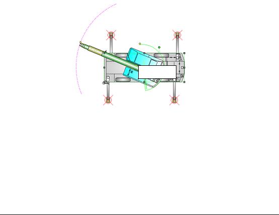
(2)Confirm that there is no live part in the swivel range and the wrecker installation place.
Swivel range (within circle)
Wrecker
Figure 116 Swivel range of wrecker
4.Assembling and organizing of dustproof place
(1)The place shall be ensured enough space for assembling equipment
(2)Dust, dirt, etc. shall not be inside of the dustproof place.
5.Tool
Tools which are well maintained shall be used
23

6. Clothes |
|
|
|
|
|
|
|
|
|
|
|
According |
to |
the |
departmental |
order, |
wear |
the |
clothes, |
hat, |
and |
shoes |
which |
non-electroconductive and dustproof. |
|
|
|
|
|
|
|
|
|||
Article 117. Against dust during the assembly work
The provisions of this article shall refer to the Article 116.
Article 118. Apparel for worker
As stipulated in Technical Regulation.
Article 119. Check before starting assembly
The on-site installation work of GIS shall be conducted as follows.
1.Confirmation of foundation and position of ground line
It shall be collated surely with the drawing, and confirm that they are the same as which shown in the drawing.
2.Installation position setting in accordance with the drawing
It shall be collated surely with the drawing, and confirm that they are the same as which shown in the drawing.
3.Confirmation of horizontal degree
After installation, the degree of horizontal shall be confirmedIt. shall be confirmed that the air bubble displacement is below 0.5mm in the spirit level.
4.Confirmation of oxygen density in the GIS tank
The work shall be started after confirming that the oxygen density in the GIS tank is 18% or more by using oxygen meter.
5.Cleaning of GIS tank
Before assembling and connecting, the GIS tank inside shall be cleaned, and the followings shall be noted
(1) |
It shall be checked visually whether there are not any crack, deformation, foreign matters, etc. |
|
|
in the connection part (flange |
spacer, etc.). |
(2) |
While cleaning inside of a |
GIS tank, it shall be checked that there are not any crack, |
modification, foreign matters, and omission of objects such as bolts and pins inside of the GIS tank.
(3)It shall be checked that there are not any crack, modification, and foreign matters in internal connection parts (conductor part and contactor).Also conductive grease shall be applied to a conductor terminal area.
6.Confirmation of join part size
The joint part shall be measured, and be confirmed that the size is the same as which shown in the drawing.
24

7. Confirmation of O ring surface and its size
It shall be checked that there are not any crack and adhesion ofgnforeisubstance on O ring surface. It is checked that the size is the same as which shown in the drawing.
The grease seal is applied to O ring surface.
8.Connection of unit
The unit connection shall be conducted surely using a guide pin etc so that the innerconductor is connected appropriately without the excessiveness.
9.Use of torque wrench for tightening joint part
In case of fastening a bolt with excessive torque, the bolt may break and the effect of |
spring |
washer is lost, therefore, the bolt shall fastenedbe with adequate torque specified by |
the |
manufacturer. |
|
10.Installation of adsorbent*
It shall be checked that the installation position of the absorbent is the same as which shown in the drawing.
Article 120. The time of unit connection
At the time of unit connection, centering of the internal conductor shall be carried out so that the conductor is connected within the manufacturer's specified error under the manufacturer's orders.
Article 121. Grease for the connecting part
The provisions of this article shall refer to the Article 119.
Article 122. Tightening bolts Use of torque wrench
The provisions of this article shall refer to the Article 119.
Article 123. The duration of exposure of adsorbent to atmosphere
The provisions of this article shall refer to the Article 119.
Article 124. Making vacuous and filling up SF6
Gas treatment
1.The measure against foreign matters of gas recycle equipment
It shall be confirmed that there is not any foreign matters in the connected part etcof. the recycle unit and be cleaned as needed.
It shall be checked that the filter is equipped and there is not any crack.
2.Vacuum influence
Vacuum degree is confirmed by a pressure gaugeIt. is preferable tocontinue vacuuming for 30 minutes or more after it has reached 133Pa in GIS tank.
3.Gas charging
Gas in GIS tank shall be charged at rated pressure according to the outside temperature.
25

Article 125. SF6 gas analysis
The confirmation of filled gas shall satisfy the following.
1.Measurement of moisture in gas
Measured moisture content in the gas shall be less than the value instructed by the manufacturer. If the value is not provided by the manufacturer, the measured moisture content in the gas should be less than the values below.
500ppm or less: the device which generates dissolution gas 150ppm or less: the device which doesn’t generate dissolution gas
2.Gas purity
More than 97% of gas purity is required
More than 98% of purity of new gas is required.
3.Gas leakage test
Gas leakage test of parts which was assembled on site is inspected by a gas leak detector.
(1)Test method
Accumulation method shall be designated as the standard test method, and trace method is used only for the region that the accumulation method can not be performed easily.
The accumulation method: Surround the tank-binding part and whole gas fitting circumference with polyethylene sheets, the accumulated leakage gas in the sheets shall be detected with the gas leak detector after the appropriate time elapsed.
Figure 125 Accumulation method for gas leakage test
The trace method: The existence of gas leak is checked by bringing gas leak detector closes to the tank connection part and gas piping directly.
(2)Test evaluation
The inspector shall confirm that a leakage gas can not be detected by gas leakage detector.
26

Article 126. SF6 gas leakage test
Regarding the waterproofing, the caulking of the joint part of GIS tank shall be carried out using sealing materials after gas leakage test.
Article 127. Gas valves in SF6 gas tank
Gas collection work flow
1.Preparation work
(1)Gas measurement of SF6 gas collect cylinder
The purity of the gas and the amount of moisture in cylinder are measured.
-The purity of the gas are more than the standard value.
-The amount of moisture are less than the standard value.
(2)Device installation and connection
The packing for connection, etc. are checked and it is exchanged if necessary.
It shall be checked with a gas distribution diagram not to remove gas from non-targeted unit.
It shall be confirmed that the spacer of the gas division will not be damaged by performing vacuum pulling.
SF6 Gas |
Spacer Tank |
Spacer Tank |
|
|
GIS Tank
Conductor
SF6 Gas
Figure 127 Spacer of gas division
(3)Measurement and record of cylinder weight Measurement and record of single cylinder weight
Measurement and record of cylinders and hose after the connection
(4)Gas measurement and record of objective equipment
The purity of the gas and the amount of moisture in objective equipment shall be measured, and it is checked that they satisfy the standard values.
In case of the driving equipment, cracked gas (sulfur dioxide SO2, hydrogen fluoride HF) shall be measured and confirmed that they are undetected.
27
