

книги / Переработка нефти и газа
..pdfFurther, it is necessary to record formation temperature for each 10 % vol., of oil product under analysis. It can be determined by the cylinder level.
When 90 % vol. of oil product is distilled, heating is controlled so that it takes from 3 to 5 minutes to complete distillation, i.e. to stop heating. Heating should be stopped when fluid volume in the cylinder becomes equal to the highest regulated distillation amount (97.5; 98 and other) for the given oil product. To determine end boiling point, heating is provides until mercury ball of the thermometer stops and, then, goes down. The highest reading of the thermometer corresponds to the end boiling point.
Laboratory Work 2 (2 hours)
SATURATED VAPOR PRESSURE DETERMINATION
Vapor which is in equilibrium with liquid is termed Saturated Vapor. Vapor pressure in saturated condition is the highest for the given temperature. Boiling point is the temperature when saturated vapor pressure is equal to external pressure. Thus, for determining saturated vapor pressure, it is sufficient to determine boil-off vapor pressure. Saturated vapor pressure characterizes evaporation rate, motor fuel startability and vapor locking tendency.
It is recommended to store saturated vapor sample at temperature not higher 20оС.
Device for determining saturated vapor pressure (fig. 2) consists of metal bomb, water bath and pressure gage. Metal apparatus (Reid vapor pressure bomb) consists of two parts: fuel chamber 1 and air chamber 2, which are thread connected. Ratio of air chamber volume to fuel chamber volume can range from 3.8 to 4.2. Bath temperature should be maintained at constant level 38 ±0.3оС by thermostat with control thermometer. Before test, the air chamber must be washed with 30–40 оС water for at least 5 times to remove fuel vapor. Connect rubber tube to the nozzle and clamp it.
Before test, it is necessary to place fuel sample and fuel chamber in 0–4 оС ice bath. Then, after rinsing 3 times the fuel chamber with fuel to be tested, fill it wit fuel so that it does not overflow at the top of the chamber.
Fig. 2
51
After taking the initial air temperature in the air chamber, it is necessary to check tube clamping and connect the air chamber with the fuel chamber. Bring the chambers in the normal position and place them in water bath.
When the chambers are placed in water bath, unclamp and, in 5 minutes, take pressure by pressure gage reading. Then, clamp, take the chambers out of the water bath, and, having overturned them, shake them and place again in the water bath. Test should be repeated each 2 minutes until pressure gage reading ceases changing. Before each shaking, the clamp should be closed, and unclamp when the assembled apparatus is in the water bath. Shake it as fast as possible to prevent cooling. Mounting flange is used to prevent overturning.
When pressure gage reading ceases changing, it is recorded as “uncorrected saturated vapor pressure” and ∆ Р correction is introduced for air pressure and water vapor pressure change in the air chamber caused by the difference between initial air temperature and water bath temperature. ∆ Р, Pa, can be calculated by formula:
∆ Р = [ ( Ра – Pt ). ( t –38 ) ]/ (273 + t ) – ( P38 – Pt ),
where Ра is atmospheric pressure in test point, Pa;
Рt is saturated water vapor pressure at initial air temperature, Pa; t is initial air temperature, оС; and
Р38 is saturated water vapor pressure at 38 оС.
After completion of testing, stop the apparatus: stop power supply, clamp thermostat tubes, take the apparatus out of the bath, disassemble it, wash the fuel and air chambers, apparatus and pressure gage connecting tube.
The below Table provides corrections calculated with accuracy 133,392 Pa by the above formula. Correction should be deducted from the “uncorrected saturated vapor pressure” if initial air temperature is lower than, and it should be added if initial air temperature is higher than 38оС.
For instance, uncorrected saturated vapor pressure is 58395 Pa, initial air chamber temperature is 18 оС, and atmospheric pressure is Ра = 99991.5 Pa. We take a correction from the Table, and it is ∆Р = –11332.4 Pa. Thus, tested fuel saturated vapor pressure is 58395 – 11332.4 =47062.6 Pa. Tolerance is ±1999.8 Pa.
52

53
Laboratory Work 3 (2 hours)
OIL VISCOSITY DETERMINATION
Viscosity is the most important physical constant characterizing performance properties of boiler and diesel fuels, hydrocarbon oils and other oil products. Viscosity magnitude shows us oil spray and circulation capability.
In oil refining, there are dynamic, kinematic and funnel viscosity.
Dynamic (absolute) viscosity or internal friction is fluid property to resist tangent shearing forces. Such property manifests itself under fluid flow. Unit of measurement is N.sec/m2 – resistance of fluid under flow of 1 m2 two layers separated one from another and flowing under action of external force 1 N with velocity 1 m/sec. Considering that N/m2=Pa, dynamic viscosity is often expressed in Pascal-second (Pa.sec) or millipascal-second (mPa.sec).
Kinematic viscosity is widely used for various calculations and oil product quality control.
Kinematic viscosity is ratio of fluid dynamic viscosity to fluid density at the same temperature. It is measured in m2/sec or mm2/sec.
Often, oil and oil products are characterized by funnel viscosity which is ratio of 200 ml oil product flow time through calibrated hole of standard viscosimeter to 200 ml distilled water flow time at 20 оС. Funnel viscosity is expressed by number of conditional degrees.
Kinematic Viscosity Determination
Most often, glass viscosimeters are used for determining kinematic viscosity. In glass viscosimeters, fluid flows through capillary tubes of defined diameter. The essence of the method is measurement of flow time of defined fluid volume under gravity. Capillary diameter should be selected so that fluid flow time is not less than 200 seconds. The method is based on Poiseuille formula for real fluid flow through capillaries:
ν=πghr4τ/8 LV, where ν is kinematic viscosity, m2/sec;
gis gravity acceleration, m/sec2;
his fluid column height, m;
r is capillary radius, m; L is capillary length, m;
V is fluid volume flowing through capillary; and τ is fluid volume flow time.
54
Considering that h, r, L and V are constant for the given viscosimeter, we can put
πghr4/8LV=C,
then
ν= С τ,
where С is viscosimeter constant, mm2/sec2.
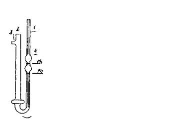
Viscosimeter constant must be shown in certificate to be provided with each viscosimeter. Depending on oil product brightness and viscosity, VPZhT-2 (ВПЖТ- 2) (fig. 3) and VPZhT-4 (ВПЖТ-4) (fig. 4) viscosimeters are used for measuring bright fluid viscosity at all temperatures.
Thermostat or viscosimeter bath is filled with bright fluid which is retained in the liquid state for temperature measurement. Any transparent vessel can be used as bath. The depth of such transparent vessel shall be so that viscosimeter oil product is, for at least, 20 mm lower than bath fluid level and 20 mm above the bottom of the bath. The bath must be equipped with devise which makes it possible to control fluid temperature in the bath. Fluid temperature change along the entire viscosimeter length shall not exceed ±0.01 оС at temperature from 15 up to 100 оС.
Dry viscosimeter with range sufficient for measuring the expected viscosity of sample to be tested should be used (fig. 3 and fig. 4). If oil product contains water, it should be dried by anhydrous sodium sulfate or heat treated large-grained salt (sodium chloride), and filtrated through paper filter.
Fig. 3 |
Fig. 4 |
Before heating, viscous products may be heated to 50–100 оС. To determine viscosity, rubber tube is put on the drain tube 3 of the viscosimeter. Then, it is
55
necessary to cover the elbow 2 with finger and overturn the viscosimeter, omit the elbow 1 to the vessel with oil product and fill it (using pipette bulb, water jet injector or other) to М2 level observing that no air bubbles are formed in fluid. The viscosimeter is taken out of the vessel and quickly placed in the normal position. Fluid surplus is removed from the outer side of the elbow 1 end and put it on the rubber tube end. The viscosimeter is placed in the thermostat (bath) so that extension 4 is lower than fluid level. After holding in the thermostat for the least 15 minutes, fluid is sucked into the elbow 1 to about 1/3 height of the extension 4. The elbow 1 is connected with atmosphere, and fluid meniscus shift from М1 point to М2 point is measured. Kinematic viscosity of oil product (ν), mm2/sec, is calculated by formula:
ν=С τ,
where С is viscosimeter constant, mm2/sec2; and
τ is arithmetic average flow time of oil product in the viscosimeter, sec.
Dynamic viscosity of oil product (η), MPa.sec, is calculated by formula:
η=ν ρ,
where ν is kinematic viscosity, mm2/sec; and
ρ is density at the same temperature, g/cm3.
Divergence of successful determinations should not exceed 0.35 % of arithmetic average value.
Determined kinematic and dynamic viscosity magnitude is rounded to 0.01 %.
Laboratory Work 4 (2 hours)
OIL PRODUCT WATER CONTENT DETERMINATION
Water always accompanies oil. Water solubility in oil is low, but it forms with oil true emulsions. At the same time, it is undesirable, and, in some cases, even unacceptable, that oil, oil products (lube oils, carburetor and diesel fuels, jet fuels and other) contain water. Carburetor and diesel fuel contained water affects fuel calorific value, clogs and causes spray nozzle plugging. At low temperature, ice crystals clog filters and can cause failure of aviation engine operation. Lube oil water promotes oil oxidation tendency, accelerates corrosion of metal parts contacting lube oil.
56
Thus, water affects both oil refinery process and oil product performance characteristics, and water content must be strictly regulated.
The simplest and fairly accurate method for oil product water content determination is oil distillation with solvents. Dean and Stark method has received wide recognition, and has been accepted as standard method by almost all countries.
Azeotropic Distillation under Dean and Stark Method
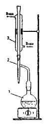
Fig. 5. Oil Product Water Content Determination Device 1 – flask; 2 – receiver-trap; 3 – cooler
The essence of the method is water and solvent distillation from oil product, and further separation in the graduated receiver into two layers. Gasoline with boil-off temperature over 80 оС is used as solvent. Before using, solvent should be dewatered by calcium chloride or sodium sulfate, and filtered. Apparatus for determining water content (fig. 5) consists of flask 1, receiver–trap 2 and cooler 3. The receiver is a calibrated 10 ml test tube with tapered bottom part. Graduation scale mark is 0.2 ml within the section from 1 up to 10 ml. and 0.05 ml within the section from 0 up to 1 ml. Drain tube is soldered to the top part of the test tube. The receiver-trap is connected to the flask and cooler by cork stopper or by joints.
Procedure
Oil product sample should be stirred for five minutes, and thick and high-wax oil products are preheated to 40 оС.
100 g of oil product is weighted by counter balance and placed in dry clean flask. Then, 100 ml of solvent is added and stirred. For uniform boiling, some pieces of capillaries are introduced into the flask.
The cooler, cleaned with cotton wool, is connected to the receiver-trap so that the lower edge of the tapered tube end is opposite the middle of the drain tube. The flask contained oil product and solvent is connected to the drain tube of the receiver-trap so that the tube end penetrated the flask on 15–20 mm.
When the apparatus is assembled and installed on the support, water should be directed to the cooler and flask should be slowly heated by closed-type electric hot plate. Heating is controlled by laboratory transformer so that 2–4 drops of condensate
57
flow to the receiver-trap from the cooler per second. In some time, the receiver-trap will be filled with fluid, and fluid excess will flow back to the flask. If oil product under testing contains water, water being evaporating from the flask and condensing in the cooler, flows together with solvent to the trap, and settled to the lower layer due to density difference.
When water amount in the trap ceases to grow, and the upper layer of solvent becomes bright, distillation should be stopped. Distillation time should be not more than 1 hour. If there are some water in the receiver-trap, and solvent is not bright, the receiver-trap should be placed in hot water for 20 minutes for solvent brightening. Water drops on the trap walls can be removed with thin glass bar.
After cooling, the apparatus is disassembled. Water in the trap in amount of less than 0.03 ml is considered as traces.
Water content X in mass percent can be calculated by formula:
X= (V/G)100,
where V is volume of water in trap, ml; and G is weight of oil product under test, g.
58
Course of lectures on
OIL REFINING. FUEL PRODUCTION
Lecture 1
INTRODUCTION
OVERVIEW AND CLASSIFICATION OF OIL
CHEMICAL TREATMENT PROCESSES
As distinct from Part I of the course that addressed processes of oil and gas physical separation into their components, the present Section deals with oil chemical treatment processes. Appropriate production processes are lined up according to their affinity in the sequence stated below.
Oil Treatment Thermal Processes
1.Thermal cracking of liquid oil under high pressure (from 20 through 70 atmospheres, visbreaking).
2.Thermal cracking of residues under low pressure (coking, destructive distillation).
3.Pyrolysis of liquid and gaseous oil.
All the above processes are characterized by high temperatures within the reaction zone – from 450 to 1,200 °С. High temperature decomposes oil (cracking). This process is accompanied by secondary consolidation reactions of newly formed hydrocarbon molecules.
Thermal cracking under high pressure is used to treat relatively light raw materials (from naphtha to fuel oil inclusive) to obtain motor fuel. The process takes place at 470–540 °С.
Normally, end product of treating residues i.e. tars is boiler fuel obtained as a result of original residue viscosity reduction. Such a process of raw material superficial decomposition is term either primary cracking or visbreaking. Visbreaking takes place under pressure of about 20 atmospheres.
Thermal cracking of residues under low pressure is carried out in the direction of their decarbonization i.e. concentration of asphaltic resinous components in a solid product i.e. the coke, and obtaining due to this of products with higher hydrogen content such as gasoil, gasoline and gas. Such a form of thermal cracking is termed coking. Coke would sometimes become end product of this process.
59
A variety of residue thermal cracking under low pressure, i.e. so-called destructive distillation aims at obtaining a maximum yield of kerosene-type distillates with a minimum amount of heavy liquid residue.
Coking and destructive distillation take place under nearly atmospheric pressure and temperature of 450–550 °С.
Pyrolysis is the hardest form of thermal cracking. It uses various raw materials. The process temperature is 770–800 °С and upwards, its pressure is close to atmospheric level. The process aims at obtaining gaseous unsaturated hydrocarbons mainly ethylene. It provides such side products as aromatic hydrocarbons (benzene, toluene and naphtalene).
Catalytic Processes of Cracking and Reforming
1.Catalytic cracking of raw materials similar to gasoil (rarer residues) uses silica-alumina catalysts.
2.Catalytic reforming (transformation) of gasoline cuts uses platinum or oxine molybdenum catalyst.
Catalytic cracking mainly aims at obtaining gasoline and diesel fuel. The process temperature is 450–500 °С i.e. it is close to thermal cracking temperature, but the process provides gasoline of significantly higher quality.
Essence of catalytic cracking consists in gasoline cuts aromatization that results from catalytic transformation of naphthenic and paraffin hydrocarbons. The process gives such products as high-octane aromatized gasoline or, following required stripping operations, individual aromatic hydrocarbons (benzene, toluene and xylenes) used in petrochemical industry.
Hydrogenation Processes
Oil thermocatalytic transformations under hydrogen pressure could provide cracking products of a fairly suitable composition. Hydrogen impact depth and purpose are used to distinguish the following hydrogenation processes:
1.Hydrotreating. The process is intended to upgrade gasoline, diesel fuels, lubricants and other oil derivatives by breaking down sulfur compounds contained in them and to remove sulfur as hydrogen sulfide.
2.Destructive hydrogenation. The process consists in cracking of solid and liquid raw materials under the pressure of 300–700 atmospheres. High partial pressure of hydrogen within the reaction zone enables to crack such heavy raw
60