

pdfcoffee.com-by-charles-w-cosimano
.pdfTake a plastic coffee-can cover and lay it flat of on a table in front of you. Hold it by the edges with your left hand and with your right, gently rub your thumb over it. As you do this, repeat to yourself a statement that you know to be true, such as 2+2=4. Your thumb should suddenly encounter a strong resistance on plate and be stopped. If that occurs, you are ready to build a radionic box. If not, your dowsing skills need more work, so repeat the exercises in the next chapter.
Assuming that your thumb has been stopped, you are ready to make your portable detector. This little gadget, in addition to being an excellent dowsing instrument in its own right, is essential in the use of the radionic machines you will be building.
As you can see from the drawing, this device is extremely simple in design. To make it, you will need the plastic cover, three feet of uninsulated copper wire, usually sold as magnet wire, six feet of double strand speaker cable, one mono plug and a few minutes.
You start by making two small cuts in the edge of the plate for the wire to fit in. After you have done this, make a coil with the magnet wire. The number of turns in the coil is not important. Place the coil on the plate and arrange the two ends of the wire so that they are stuck in the slits. Tape the coil in place. Now connect the ends of the magnet wire to the speaker wire, on end to each strand. Twist the wires to make a firm connection of each. Wrap the arrangement in electric tape and reinforce the wires in the slits with the same tape so that they will not break under stress.
Take the plug apart, put the shield of the plug onto the wire, with the threaded end facing the plug. Attach speaker wire to the plug in the places provided and re-attach the shield.
Having completed your detector, you are now ready to build your first radionic box. To make this box, you will need three radio potentiometers, (value not important) three dials, calibrated if possible, otherwise you will have to make your own calibration, two jacks, the same diameter as the plug you used on the portable detector, two cans, four screws with nuts (your relatives don't count), hook-up wire and something to put it in. A cardboard box will work quite well.
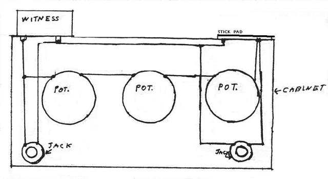
The machine is wired as in the figure . When completed, the circuit will run from one can, through the three potentiometers, to the second can and back to the first. The insertion of the detector plug in either jack does not take that can out of the system, but the detector, or anything else, becomes part of the circuit at that point. Hence, by plugging the detector in the right-hand jack, the operator is able to get a signal from the witness in the left can and by plugging and amplifier into the left jack, the operator can influence the subject of the witness in the right can. What's a witness? It gets explained in the next chapter.
This box is useful for all operations involving radionics. It can analyze, transmit and receive. It is your basic box and you may want to make more than one of this pattern.
But, before you go on, if you are not familiar with the workings of a radionic box, study the appendix on how to operate them.
The five dial instrument is as illustrated in the next two drawings and is a very special device. It is a radionic box which has been specifically designed for use as a weapon. It has no other use than to attack the etheric body of an enemy. It cannot analyze or defend and may be dangerous to use in the communication experiments in my other books.
Keep this in mind as you build it.

You will immediately notice that on the face of this machine is the figured of the inverted pentagram, traditional sign of evil. One would think that in using these devices we would be getting away from this sort of thing, but that is not the case. The design is integral to the functioning of the machine. You will understand this better when you study transmittal patterns.

To make this device, you will need five potentiometers, two jacks, five dials, two cans, four screws with nuts, and hook-up wire. The cabinet may be another cardboard box, but the face must be clear of any writing. It may be a good idea to glue a plain sheet of paper over it to be sure.
You start this project by making the inverted pentagram on the face of the box. This must be exact. With a compass, draw a circle on the box. Using a protractor and ruler, locate five points on the circle at 72 degrees apart, with one point at the bottom. Draw the lines of the pentagram and then erase the circle. Go over the lines with a magic marker and make your holes for the potentiometer stems at each point of the star.
Turn the box around and insert the potentiometers as shown. remember that the view is reversed, so the #1 potentiometer will be on the right when you wire it and on the left when you use the machine. This is the only machine in which such things are important and this case they are extremely important. You must wire the box as it is shown in the diagram. Beginning with pot 1, wire 2, 3, 4, and 5 as shown. Wire pot 1 to the can over it and 5 to the other, connecting the cans as in the other box. The jacks are wired the same

as in the other box. When properly made, the energy transmitted will start at the can on the left, go through the five potentiometers following the pattern and picking up the energy inherent in that pattern to come out with devastating force in the second can. Or, to paraphrase an old song, "You put the witness in here, the forces go round and round and they come out here."
There are some precautions that must be observed in the use of this machine, so read that section carefully before you begin to use it. This can be a dangerous machine to the very sensitive, though the average person should encounter no difficulty with it.
The remaining radionic devices are based on a gadget called the Magnetron. The
Magnetron is unusual is that it is based on an electronic mechanism by the same name which was put together with no thought of anything psychic in mind. During the Second World War, British radar researchers were looking for a way to transmit on the 10 cm band. The Klystron was already in use, but the models at that time were not powerful enough. So a pair of engineers came up with an idea. They made a device with a solid copper core with eight holes placed around a central, larger hole connected to it by small veins. This shape did something weird to the electron flow and the experiment was a resounding success.
In the mid 1950's, a pair of French radiathesists, which is a fancy word for dowsers, named Servanx (brothers) looked at the magnetron and had another idea. If the design of the core influenced electron flow, might not the same design drawn on paper influence the
flow of a subtler energy. On the surface, the idea seemed ridiculous, but that has never stood in the way of the French and they tried it. To everyone's surprise, it worked.
The magnetron might have sat with them, had not another group of researchers working under Christopher Hills decided that the Magnetron would be a good substitute for a radionic instrument. They did a few more experiments and decided that by adding magnets at the outer circles, arranged in alternating polarities, the output of the device was improved.
This author, after reading a description of the Hills device, went to work and created a further modification. The vanes connecting the central circle with the smaller circles were removed, leaving a large circle in the center surrounded by eight unconnected, smaller circles. In the Hills' device, the eight magnets are set into the center of each small circle, thus creating a magnetic vortex of sorts around the center. My version used magnet strip stuck under each circle. Magnet strip has the polarities arranged differently from the usual bar magnets in that the positive poles are at the ends and the negative poles are along the sides. The resulting arrangement under the magnetron pattern thus ended up looking like the drawing below. This arrangement of magnets and circle pattern proved that the circle designs around the center could be eliminated altogether, thus allowing for a flexibility in design which would not be possible in the Hills device. The reason for this seems to lie in the fact that in the Hills device there are two different principles at work; the geometric one present in the Servanx drawing, and a magnetic effect.

The eight-dial box is based on this Magnetron pattern, in spite of the fact that it bears a surface resemblance to certain radionic devices used by Dr. David Tansley in his healing practice. It is unique among the machines discussed here in that the subject witness sample and transmittal patterns are both placed in the center. The jack is used for the detector or other devices.
To make this machine, you will need eight potentiometers, eight dials, one jack, one can or circular foil plate, three screws and nuts and box to put it in. You will also need some connecting wire.

Start off by drawing a circle on the front of the box, which will be the top when complete. Mark the center of the circle and, using a protractor, mark off eight points along the circle, exactly 45 degrees apart. Make a hole at each point for the potentiometers. In the base of the can, make three holes; one in the center and two at one side. It will make things much easier if the holes are the right size for the screws. Place the can over the center of the circle. It may even be a good idea to use the compass to mark off another concentric circle the same diameter as the can so that you can get this right as it is of some importance to be as exact in this as possible. Once the can is in position, punch three holes in the box by pushing the punch through the holes in the can and then the box.
Insert the three screws, placing the nuts on loosely inside the box. On the inside of the box, insert and wire the eight potentiometers as shown in the figure. The wire from the center point of each potentiometer is connected to the center screw holding the can after these connections are complete, you may tighten the nut on that screw.
Wire the jack to the other two screws as shown, punching a hole in the box for the jack itself. after you have done this, turn the box over and attach the eight dials and tighten the jack nut, holding that in place. Do the same with the potentiometers and attach and calibrate the dials.
This box will act as a very powerful transmitter and as an extremely accurate analyzer.
The number of dials, when used with a good witness and transmittal pattern gives it an accuracy greater than the other two designs. It is also one of the best psionic defensive tools available.
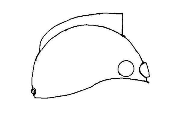
The Psionic Amplifying helmet needs a bit of explaining. The idea that it would be possible to make a head gear of some sort, usually a helmet, that could increase psychic output has been around for some time in science-fiction. The helmet you will be making is based on the Magnetron and two important facts. First, the brain reacts to small magnetic fields. Second, the etheric body also reacts to those fields. I will say at this point that we are going to be working with the etheric field rather than the electrical fields inside the brain. The magnetic field we will generate is too small to affect the latter and the type of magnetic field which is powerful enough to do that is positively dangerous to use by any but the most skilled individuals. The purpose of psychic warfare is to hurt other people, not ourselves.
To make your helmet you will need: 1 plastic hard hat
3 potentiometers
1 three inch diameter foil circle
8 one inch pieces of magnet strip
1jack
2feet of magnet wire
2 2 1/2 sheets of Styrofoam hook up wire
Start this project by inspecting the helmet. It must be plastic. Metal helmets will not work for this device. Assuming that, make certain that it fits properly. It should rest