
- •Contents
- •General Overview
- •Starting Out
- •Scripting
- •Library Part Structure
- •Analyze, Deconstruct and Simplify
- •Elaboration
- •Entry Level
- •Intermediate Level
- •Advanced Level
- •Expert Level
- •3D Generation
- •The 3D Space
- •Coordinate Transformations
- •The GDL Interpreter
- •The GDL Script Analysis
- •GDL Syntax
- •Statements
- •Line
- •Label
- •Characters
- •Strings
- •Identifiers
- •Variables
- •Parameters
- •Simple Types
- •Derived Types
- •Coordinate Transformations
- •2D Transformations
- •3D Transformations
- •Managing the Transformation Stack
- •3D Shapes
- •Basic Shapes
- •BLOCK
- •BRICK
- •CYLIND
- •SPHERE
- •ELLIPS
- •CONE
- •PRISM
- •PRISM_
- •CPRISM_
- •BPRISM_
- •FPRISM_
- •HPRISM_
- •SPRISM_
- •SLAB
- •SLAB_
- •CSLAB_
- •CWALL_
- •BWALL_
- •XWALL_
- •XWALL_{2}
- •BEAM
- •CROOF_
- •MESH
- •ARMC
- •ARME
- •ELBOW
- •Planar Shapes in 3D
- •HOTSPOT
- •RECT
- •POLY
- •POLY_
- •PLANE
- •PLANE_
- •CIRCLE
- •Shapes Generated from Polylines
- •EXTRUDE
- •PYRAMID
- •REVOLVE
- •RULED
- •RULED{2}
- •SWEEP
- •TUBE
- •TUBEA
- •COONS
- •MASS
- •Elements for Visualization
- •LIGHT
- •PICTURE
- •3D Text Elements
- •TEXT
- •RICHTEXT
- •Primitive Elements
- •VERT
- •TEVE
- •VECT
- •EDGE
- •PGON
- •PIPG
- •COOR
- •BODY
- •BASE
- •Cutting in 3D
- •CUTPLANE
- •CUTPOLY
- •CUTPOLYA
- •CUTSHAPE
- •CUTFORM
- •Solid Geometry Commands
- •GROUP
- •ENDGROUP
- •ADDGROUP
- •SUBGROUP
- •ISECTGROUP
- •ISECTLINES
- •PLACEGROUP
- •KILLGROUP
- •SWEEPGROUP
- •Binary 3D
- •2D Shapes
- •Drawing Elements
- •HOTSPOT2
- •LINE2
- •RECT2
- •POLY2
- •POLY2_
- •POLY2_A
- •POLY2_B
- •POLY2_B{2}
- •POLY2_B{3}
- •CIRCLE2
- •SPLINE2
- •SPLINE2A
- •PICTURE2
- •PICTURE2{2}
- •Text Element
- •TEXT2
- •RICHTEXT2
- •Binary 2D
- •FRAGMENT2
- •FRAGMENT2
- •3D Projections in 2D
- •PROJECT2
- •PROJECT2{2}
- •PROJECT2{3}
- •Drawings in the List
- •DRAWING2
- •DRAWING3
- •DRAWING3{2}
- •DRAWING3{3}
- •Graphical Editing
- •Hotspot-based Editing Commands
- •HOTSPOT
- •HOTLINE2
- •HOTARC2
- •Status Codes
- •Status Code Syntax
- •Additional Status Codes
- •Previous part of the polyline: current position and tangent is defined
- •Segment by absolute endpoint
- •Segment by relative endpoint
- •Segment by length and direction
- •Tangential segment by length
- •Set start point
- •Close polyline
- •Set tangent
- •Set centerpoint
- •Tangential arc to endpoint
- •Tangential arc by radius and angle
- •Arc using centerpoint and point on the final radius
- •Arc using centerpoint and angle
- •Full circle using centerpoint and radius
- •Attributes
- •Directives
- •Directives for 3D and 2D Scripts
- •RADIUS
- •RESOL
- •TOLER
- •LINE_PROPERTY
- •[SET] STYLE
- •SET STYLE 0
- •Directives Used in 3D Scripts Only
- •MODEL
- •[SET] MATERIAL
- •SECT_FILL
- •SHADOW
- •Directives Used in 2D Scripts Only
- •DRAWINDEX
- •[SET] FILL
- •[SET] LINE_TYPE
- •Inline Attribute Definition
- •Materials
- •DEFINE MATERIAL
- •DEFINE MATERIAL BASED_ON
- •DEFINE TEXTURE
- •Fills
- •DEFINE FILL
- •DEFINE FILLA
- •DEFINE SYMBOL_FILL
- •DEFINE SOLID_FILL
- •DEFINE EMPTY_FILL
- •Line Types
- •DEFINE LINE_TYPE
- •DEFINE SYMBOL_LINE
- •Styles
- •DEFINE STYLE
- •DEFINE STYLE {2}
- •Paragraph
- •Textblock
- •Additional Data
- •External file dependence
- •Non-Geometric Scripts
- •The Properties Script
- •DATABASE_SET
- •DESCRIPTOR
- •REF DESCRIPTOR
- •COMPONENT
- •REF COMPONENT
- •BINARYPROP
- •SURFACE3D ( )
- •VOLUME3D ( )
- •POSITION
- •DRAWING
- •The Parameter Script
- •VALUES
- •PARAMETERS
- •LOCK
- •HIDEPARAMETER
- •The User Interface Script
- •UI_DIALOG
- •UI_PAGE
- •UI_CURRENT_PAGE
- •UI_BUTTON
- •UI_SEPARATOR
- •UI_GROUPBOX
- •UI_PICT
- •UI_STYLE
- •UI_OUTFIELD
- •UI_INFIELD
- •UI_INFIELD {2}
- •UI_INFIELD{3}
- •UI_TOOLTIP
- •Expressions and Functions
- •Expressions
- •VARDIM1(expr)
- •VARDIM2(expr)
- •Operators
- •Arithmetical Operators
- •Relational Operators
- •Boolean Operators
- •Functions
- •Arithmetical Functions
- •CEIL
- •ROUND_INT
- •Circular Functions
- •Transcendental Functions
- •Boolean Functions
- •Statistical Functions
- •Bit functions
- •BITTEST
- •BITSET
- •Special Functions
- •String Functions
- •SPLIT
- •STRLEN
- •STRSTR
- •STRSUB
- •Control Statements
- •Flow Control Statements
- •NEXT
- •GOTO
- •GOSUB
- •RETURN
- •END / EXIT
- •Parameter Buffer Manipulation
- •Macro Objects
- •The Output Statement
- •File Operations
- •OPEN
- •INPUT
- •VARTYPE
- •OUTPUT
- •CLOSE
- •Miscellaneous
- •Global Variables
- •General environment information
- •Story information
- •Fly-through information
- •General element parameters
- •Object, Lamp, Door, Window parameters
- •Object, Lamp parameters
- •Object, Lamp, Door, Window parameters - available for listing and labels only
- •Object, Lamp parameters - available for listing and labels only
- •Window, Door and Wall End parameters
- •Window, Door parameters - available for listing and labels only
- •Lamp parameters - available for listing and labels only
- •Label parameters
- •Wall parameters - available for Doors/Windows
- •Wall parameters - available for listing and labels only
- •Column parameters - available for listing and labels only
- •Beam parameters - available for listing and labels only
- •Slab parameters - available for listing and labels only
- •Roof parameters - available for listing and labels only
- •Fill parameters - available for listing and labels only
- •Mesh parameters - available for listing and labels only
- •Free users’ globals
- •Requests
- •REQUEST
- •Doors and Windows
- •General Guidelines
- •Creation of Door/Window Library Parts
- •3D related challanges
- •Rectangular Doors/Windows in Straight Walls
- •Non-Rectangular Doors/Windows in Straight Walls
- •WALLHOLE
- •WALLNICHE
- •Rectangular Doors/Windows in Curved Walls
- •Non-Rectangular Doors/Windows in Curved Walls
- •2D Related Challanges
- •Cutting custom wall opening
- •WALLHOLE2
- •WALLBLOCK2
- •WALLLINE2
- •WALLARC2
- •GDL Created from the Floor Plan
- •Keywords
- •Common Keywords
- •Reserved Keywords
- •3D Use Only
- •2D Use Only
- •Non-Geometric Scripts
- •Property Script
- •Parameter Script
- •Interface Script
- •Alphabetical List of Current GDL Keywords
- •Parameter Naming Convention
- •GDL Data I/O Add-On
- •Description of Database
- •Opening a Database
- •Reading Values from Database
- •Writing Values into Database
- •Closing Database
- •GDL DateTime Add-On
- •Opening Channel
- •Reading Information
- •Closing Channel
- •GDL File Manager I/O Add-On
- •Specifying Folder
- •Getting File/Folder Name
- •Finishing Folder Scanning
- •GDL Text I/O Add-On
- •Opening File
- •Reading Values
- •Writing Values
- •Closing File
- •Property GDL Add-On
- •OPEN
- •CLOSE
- •INPUT
- •OUTPUT
- •GDL XML Extension
- •Opening XML Document
- •Reading XML Document
- •Modifying XML Document
- •Index
- •Numerics

Non-Geometric Scripts
LOCK
LOCK name1 [, name2, ..., namen]
Locks the named parameter in the settings dialog box. A locked parameter will appear grayed in the dialog box and its value cannot be modified by the user.
HIDEPARAMETER
HIDEPARAMETER name1 [, name2, ..., namen]
Hides the named parameter(s) and its child parameters in the settings dialog box. A parameter hidden using this command in the parameter script will automatically disappear from the parameter list.
THE USER INTERFACE SCRIPT
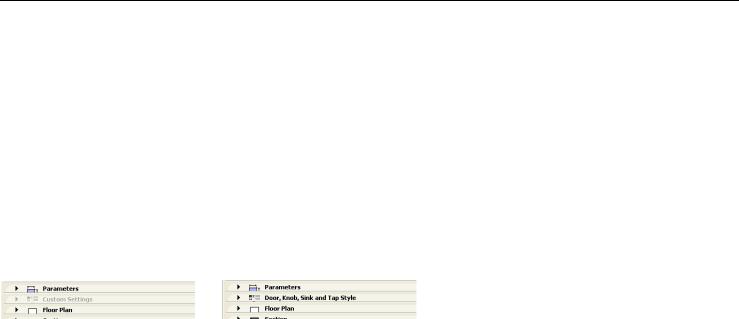
Using the following GDL commands, you can define a custom interface for a Library Part’s Custom Settings panel in the settings dialog box. If you click the “Set as default” button in the Library Part editor, the custom interface will be used by default in the Object’s (Door’s, Window’s, etc.) settings dialog box. Parameters with custom control are not hidden automatically on the original parameter list, but they can be hidden manually in the library part editor.
The origin of the coordinate system is in the top-left corner. Sizes and coordinate values are measured in pixels.
UI_DIALOG
UI_DIALOG title [, size_x, size_y]
Defines the title of the dialog box. Currently, the size of the available area is fixed at 444 x 266 pixels, and the size_x and size_y parameters are not used.
Restriction: The Interface Script can contain only one UI_DIALOG command.
UI_PAGE
UI_PAGE page_number
Page directive, defines the page that the interface elements are placed on. Page numbering starts at 1. Moving between pages can be defined in two different ways. The first method is to use two buttons created with the UI_NEXT and UI_PREV commands. The second way is to create dynamic page handling using the UI_CURRENT_PAGE command.
If there is no UI_PAGE command in the Interface Script, each element will be placed on the first page by default.
ArchiCAD 11 GDL Reference Guide |
185 |

Non-Geometric Scripts
Warning: Any break of continuity in the page list forces the insertion of a new page without buttons, and therefore no possibility to go to any other page from there.
UI_CURRENT_PAGE
UI_CURRENT_PAGE index
Definition of the current tabpage to display.
Warning: Jumping to a non-existent page forces the insertion of a new page without buttons and controls, and therefore there is no possibility to go to any other page from there.
index: valid index of the UI_PAGE to display
UI_BUTTON
UI_BUTTON type, text, x, y, width, height [, id [, url]]
Button definition on current page. Buttons can be used for various purposes: moving from page to page, opening a web page or performing some parameter-script defined action.
type: type of the button as follows
UI_PREV: if pressed, the previous page is displayed UI_NEXT: if pressed, the next page is displayed
UI_FUNCTION: if pressed, the GLOB_UI_BUTTON_ID global variable is set to the button id specified in expression UI_LINK: if pressed, the URL in expression is opened in the default web browser
text: the text that should appear on the button x, y: the position of the button
width, height: width and height of the button in pixels id: an integer unique identifier
url: a string containing a URL
UI_PREV and UI_NEXT buttons are disabled if the previous/next page is not present. If these buttons are pushed, the gs_ui_current_page parameter of the library part is set to the index of the page to show - if there's a parameter with this name.
Example:
! UI script
UI_CURRENT_PAGE gs_ui_current_page
UI_BUTTON UI_FUNCTION, "Go to page 9", 200,150, 70,20, 3 UI_BUTTON UI_LINK, "Visit Website", 200,180, 100,20, 0, "http://www.graphisoft.com"
186 |
ArchiCAD 11 GDL Reference Guide |

Non-Geometric Scripts
! parameter script
if GLOB_UI_BUTTON_ID = 3 then parameters gs_ui_current_page = 9, ...
endif
UI_SEPARATOR
UI_SEPARATOR x1, y1, x2, y2
Generates a separator rectangle. The rectangle becomes a single (vertical or horizontal) separator line if x1 = x2 or y1 = y2 x1, y1: upper left node coordinates (starting point coordinates of the line)
x2, y2: lower right node coordinates (endpoint coordinates of the line)
UI_GROUPBOX
UI_GROUPBOX text, x, y, width, height
A groupbox is a rectangular separator. It can be used to visually group logically related parameters. text: the title of the groupbox
x, y: the position of upper left corner width, height: width and height in pixels
UI_PICT
UI_PICT expression, x, y [,width, height[, mask]]
Picture element in the dialog box. The picture file must be located in one of the loaded libraries.
expression: file name or index number of the picture stored in the library part. The index 0 refers to the preview picture of the library part.
x, y: position of the top left corner of the picture.
width, height: optional width and height in pixels; by default, the picture’s original width and height values will be used. mask = alpha + distortion
See “PICTURE” element for full explanation.
ArchiCAD 11 GDL Reference Guide |
187 |

Non-Geometric Scripts
UI_STYLE
UI_STYLE fontsize, face_code
All the UI_OUTFIELDs and UI_INFIELDs generated after this keyword will represent this style until the next UI_STYLE statement. fontsize: one of the following font size values
0:small
1:extra small
2:large
face_code: similar to the STYLE definition, but the values cannot be used in combination.
0:normal
1:bold
2:italic
4: underline 8: outline 16: shadow
UI_OUTFIELD
UI_OUTFIELD expression,x,y,width,height [, flags]]
Generates a static text.
expression: numerical or string expression
x, y: position of the text block’s top left corner width, height: width and height of the pixels
flags = j1 + 2*j2 + 4*j3
j1 (1) and j2 (2) - horizontal alignment
j1 = 0, j2 = 0 : Aligns to the left edge (default) j1 = 1, j2 = 0 : Aligns to the right edge
j1 = 0, j2 = 1 : Aligns to the center j1 = 1, j2 = 1 : Not used
j3 (4): - grayed text
188 |
ArchiCAD 11 GDL Reference Guide |